
Related Manuals for Dell EMC PowerEdge MX740c


Summary of Contents for Dell EMC PowerEdge MX740c
- Page 1 Dell EMC PowerEdge MX740c Installation and Service Manual Regulatory Model: E04B Regulatory Type: E04B001 December 2020 Rev. A10...
- Page 2 A WARNING indicates a potential for property damage, personal injury, or death. © 2019 - 2020 Dell Inc. or its subsidiaries. All rights reserved. Dell, EMC, and other trademarks are trademarks of Dell Inc. or its subsidiaries. Other trademarks may be trademarks of their respective owners.
-
Page 3: Table Of Contents
Contents Chapter 1: About this document....................6 Chapter 2: PowerEdge MX740c sled overview................7 Front view of the system..............................8 Inside the system.................................8 Locating the Service Tag of your system........................9 System information label..............................10 Chapter 3: Initial system setup and configuration................ 13 Setting up your system..............................13 iDRAC configuration................................ - Page 4 Installing the drive cage............................. 37 Battery backup unit ................................. 38 Removing the battery backup unit..........................38 Installing the battery backup unit..........................39 Removing the BBU from the BBU cage.........................40 Installing the BBU into the BBU cage........................41 Control panel..................................42 Removing the control panel............................42 Installing the control panel ............................
- Page 5 Power button LED................................95 Drive indicator codes................................95 System health and system ID indicator codes......................96 System diagnostics................................96 Dell Embedded System Diagnostics........................97 Chapter 7: Getting help....................... 98 Contacting Dell EMC................................ 98 Documentation feedback..............................98 Accessing system information by using QRL......................98 Quick Resource Locator for PowerEdge MX740c system................99...
-
Page 6: Chapter 1: About This Document
The PowerEdge MX740c is compatible with the PowerEdge MX7000 enclosure. For more information about the enclosure, refer to the Installation and Service Manual for the PowerEdge MX7000 at www.dell.com/poweredgemanuals. About this document... -
Page 7: Chapter 2: Poweredge Mx740C Sled Overview
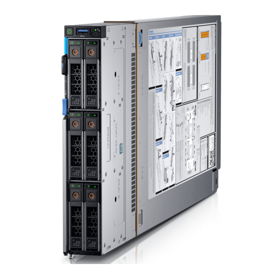
PowerEdge MX740c sled overview The Dell EMCPowerEdge MX740c is a single width compute sled and supports: ● Up to two Intel Xeon Scalable processors. ● Up to 24 DIMM slots. ● Up to six 2.5-inch SAS, SATA (HDD/SSD), or NVMe drives. -
Page 8: Front View Of The System
Front view of the system Figure 1. Front view of the 6 drive configuration 1. USB 3.0 port 2. iDRAC direct port 3. Drives 4. Release handle 5. Release handle button 6. Information tag 7. System health and System ID indicator 8. -
Page 9: Locating The Service Tag Of Your System
The System Information Tab contains the system's unique Express Service Code and Service Tag. This information is used by Dell EMC to identify system configuration, warranty terms, and to route support calls to the appropriate personnel. A Quick Resource Locator (QRL) label on the System Information Tab links to a web page that shows the exact factory configuration and specific warranty purchased. -
Page 10: System Information Label
System information label Figure 4. Mechanical overview Figure 5. Memory information PowerEdge MX740c sled overview... - Page 11 Figure 6. System board Figure 7. Removal of IDSDM and Internal USB memory key(optional) Figure 8. Removal of BBU module and drive cage PowerEdge MX740c sled overview...
- Page 12 Figure 9. Removal of backplane and Mezzanine card Figure 10. Removal of PERC cards and Mini Mezzanine card Figure 11. Removal of Jumbo PERC card PowerEdge MX740c sled overview...
-
Page 13: Chapter 3: Initial System Setup And Configuration
The Integrated Dell Remote Access Controller (iDRAC) is designed to make system administrators more productive and improve the overall availability of Dell systems. iDRAC alerts administrators about system issues and enables them to perform remote system management. This reduces the need for physical access to the system. -
Page 14: Log In To Idrac
For more information about drivers, documentation, and white papers on the Intel QAT, see https://01.org/intel-quickassist- technology. For more information about logging in to the iDRAC and iDRAC licenses, see the latest Integrated Dell Remote Access Controller User's Guide at www.dell.com/poweredgemanuals. -
Page 15: Methods To Download Firmware And Drivers
Using iDRAC virtual media www.dell.com/idracmanuals Downloading drivers and firmware Dell EMC recommends that you download and install the latest BIOS, drivers, and systems management firmware on your system. Prerequisites Ensure that you clear the web browser cache before downloading the drivers and firmware. -
Page 16: Chapter 4: Installing And Removing System Components
Damage due to servicing that is not authorized by Dell is not covered by your warranty. Read and follow the safety instructions that are shipped with your product. -
Page 17: Before Working Inside Your Sled
Before working inside your sled Prerequisites Follow the safety guidelines listed in Safety instructions on page 16. Steps 1. Power off the sled. 2. Remove the sled from the enclosure. 3. If applicable install the I/O connector cover. CAUTION: To prevent damage to the I/O connectors on the system, ensure that you cover the connectors when you remove the system from the enclosure. - Page 18 Steps 1. Press the blue release button on the sled to release the sled handle. 2. Holding the sled handle, slide the sled out of the enclosure. NOTE: Support the system with both hands while sliding it out of the enclosure. NOTE: Removing the sled with the enclosure powered on is supported if you shut down the sled before removal.
-
Page 19: Installing The Sled Into Enclosure
NOTE: The color of the I/O connector cover may differ. CAUTION: If you are permanently removing the sled, install a sled blank promptly. Operating the enclosure without a blank, for an extended time can result in overheating or performance loss. Next steps Install the sled or the... -
Page 20: System Cover
Figure 15. Installing the sled into enclosure Next steps 1. Power on the sled. System cover The system cover protects the components inside the system and helps in maintaining air flow inside the system. Removing the system cover Prerequisites 1. Follow the safety guidelines listedin Safety instructions on page 16. -
Page 21: Installing System Cover
Figure 16. Removing system cover Next steps Replace the system cover. Installing system cover Prerequisites 1. Follow the safety guidelines listed in Safety instructions on page 16. 2. Ensure that all internal cables are routed correctly and connected, and no tools or extra parts are left inside the system. Steps 1. - Page 22 Figure 17. Installing system cover Next steps Install the sled into the enclosure. 2. Turn on the sled. Installing and removing system components...
-
Page 23: Air Shroud
Air shroud The air shroud aerodynamically directs the airflow across the entire system. The airflow passes air through all the critical parts of the system thus allowing increased cooling preventing overheating. Removing air shroud Prerequisites CAUTION: Never operate your system with the air shroud removed. The system may get overheated quickly, resulting in shutdown of the system and loss of data. -
Page 24: Drives
NOTE: When firmly seated, the memory socket and processor numbers marked on the air shroud aligns with the respective memory socket and processor numbers marked on the system. Figure 19. Installing air shroud Next steps 1. Follow the procedure listed in After working inside the sled. -
Page 25: Installing Drive Blank
Figure 20. Removing drive blank Next steps Install a drive or a drive blank. Installing drive blank Prerequisites 1. Follow the safety guidelines listed in Safety instructions on page 16. CAUTION: Mixing drive blanks from previous generations of PowerEdge servers is not supported. Steps Insert the drive blank into the drive slot and push the blank until the release button clicks into place. -
Page 26: Installing Drive Carrier
Ensure that you back up your data, before removing a drive. For more information about preparing your drive for removal and supported RAID redundancy, see the Troubleshooting guide of your system at www.dell.com/poweredgemanuals. Steps 1. Press the release button to open the release handle. -
Page 27: Removing A Drive From Drive Carrier
CAUTION: Combining SAS and SATA drives in the same RAID volume is not supported. CAUTION: When installing a drive carrier, ensure that the adjacent drives are fully installed. Inserting a drive carrier and attempting to lock its handle next to a partially installed carrier can damage the partially installed carrier's shield spring and make it unusable. -
Page 28: Installing A Drive Into Drive Carrier
Figure 24. Removing a drive from drive carrier Next steps Replace the drive into the drive carrier. Installing a drive into drive carrier Prerequisites 1. Follow the safety guidelines listed in Safety instructions on page 16 Steps 1. Insert the drive into the drive carrier, with the connector end of the drive towards the back of the carrier. 2. -
Page 29: Drive Backplane
Figure 25. Installing a drive into drive carrier Drive backplane Depending on the configuration, your system supports: ● 2.5 inch (x6) Universal backplane ● 2.5 inch (x6) SAS/SATA backplane ● 2.5 inch (x4) Universal backplane Figure 26. 6 x 2.5-inch universal backplane 1. -
Page 30: Removing Drive Backplane
Figure 27. 6 x 2.5-inch SAS/SATA backplane 1. Power cable connector 2. SAS/SATA connector 3. Signal cable connector Figure 28. 4 x 2.5-inch universal backplane 1. Signal cable connector 2. AUX 1 cable connector 3. SAS/SATA connector 4. AUX 0 cable connector 5. -
Page 31: Installing Drive Backplane
Figure 29. Removing drive backplane Next steps Replace the drive backplane. Installing drive backplane Prerequisites 1. Follow the safety guidelines listed in Safety instructions on page 16 2. Follow the procedure listed in Before working inside the sled. Steps 1. Verify backplane connector pins are not bent and then connect the signal cable to the backplane. 2. -
Page 32: Cable Routing
Figure 30. Installing drive backplane Next steps 1. Connect the incoming power cable to the backplane and then verify both power and signal cable connections are fully seated to the backplane and system board. 2. Connect the integrated cable to the backplane and system board if there is no PERC card installed in the system. Install the drives. - Page 33 Figure 32. Cable routing - 4 x 2.5-inch backplane with internal PERC card Figure 33. Cable routing - 4 x 2.5 PCIe backplane with Jumbo PERC card Installing and removing system components...
- Page 34 Figure 34. Cable routing - 6 x 2.5-inch SAS/SATA backplane with internal PERC card Figure 35. Cable routing - 6 x 2.5-inch SAS/SATA backplane with Jumbo PERC card Installing and removing system components...
- Page 35 Figure 36. Cable routing - 6 x 2.5-inch SAS/SATA backplane SATA cabling Figure 37. Cable routing - 6 x 2.5-inch backplane with internal PERC card Installing and removing system components...
-
Page 36: Drive Cage
Figure 38. Cable routing - 6 x 2.5-inch backplane with Jumbo PERC card Figure 39. Cable routing - 6 x 2.5-inch backplane SATA cabling Drive cage The drive cage contains the drives and the battery backup unit module. Removing the drive cage Prerequisites CAUTION: To prevent damage to the drives and backplane, you must remove the drives from the system before... -
Page 37: Installing The Drive Cage
NOTE: Observe the routing of the cables on the chassis as you remove them from the system. You must route these cables properly when you replace them to prevent the cables from being pinched or crimped. 1. Follow the safety guidelines listed in Safety instructions on page 16. -
Page 38: Battery Backup Unit
Figure 41. Installing the drive cage Next steps Install the drive backplane. Install the drives. 3. Follow the procedure listed in After working inside your sled on page 17. Battery backup unit Removing the battery backup unit Prerequisites 1. Follow the safety guidelines listed in Safety Instructions. -
Page 39: Installing The Battery Backup Unit
Figure 42. Removing the BBU module Next steps Replace the BBU in the cage. Replace the BBU module. Installing the battery backup unit Prerequisites 1. Follow the safety guidelines listed in Safety Instructions. 2. Follow the procedure listed in Before working inside your sled on page 17. -
Page 40: Removing The Bbu From The Bbu Cage
Figure 43. Installing the BBU 3. Connect the BBU cables to the connector on the system board. Next steps 1. Follow the procedure listed in the After working inside your sled. Replace the drive carrier or a drive blank. Removing the BBU from the BBU cage Prerequisites 1. -
Page 41: Installing The Bbu Into The Bbu Cage
Figure 44. Removing the BBU from the BBU cage Next steps Install the BBU into the BBU cage. Installing the BBU into the BBU cage Prerequisites 1. Follow the safety guidelines listed in Safety Instructions. Steps 1. Align and slide the BBU into the BBU cage. 2. -
Page 42: Control Panel
Figure 45. Installing the BBU into the BBU cage Next steps Install the BBU module. Control panel The control panel allows you to manually control the inputs to the sled. Removing the control panel Prerequisites 1. Follow the safety guidelines listed in Safety Instructions. -
Page 43: Installing The Control Panel
Figure 46. Removing the control panel Next steps Install the control panel. Installing the control panel Prerequisites 1. Follow the safety guidelines listed in Safety Instructions. 2. Follow the procedure listed in Before working inside your sled. Steps 1. Align control panel with the slots on the system and slide it in. 2. -
Page 44: System Memory
Figure 47. Installing the control panel Next steps Install the drive cage. Install the drives. 3. Follow the procedure listed in the After working inside your sled. System memory The system supports DDR4 registered DIMMs (RDIMMs), load reduced DIMMs (LRDIMMs), Non-Volatile DIMMs (NVDIMM- Ns), and Intel Optane Data Center Persistent Memory Modules (DCPMMs). - Page 45 Figure 48. System memory layout Memory channels are organized as follows: Table 3. Memory channels Channel Processor 1 Processor 2 Slots A1 and A7 Slots B1 and B7 Slots A2 and A8 Slots B2 and B8 Slots A3 and A9 Slots B3 and B9 Slots A4 and A10 Slots B4 and B10...
-
Page 46: General Memory Module Installation Guidelines
General memory module installation guidelines To ensure optimal performance of your system, observe the following general guidelines when configuring your system memory. If your system's memory configurations fail to observe these guidelines, your system might not boot, stop responding during memory configuration, or operate with reduced memory. - Page 47 ● All slots on configurations 3, 6, 9, and 12 can be used, but a maximum of 12 NVDIMM-Ns can be installed in a system. NOTE: NVDIMM-N memory slots are not hot-pluggable. For more information about the supported NVDIMM-N configurations, see the NVDIMM-N User Guide at www.dell.com/ poweredgemanuals. Table 5. Supported NVDIMM-N for dual processor configurations Configuration...
-
Page 48: Dcpmm Installation Guidelines
● Mixing different capacities of RDIMMs and LRDIMMs are not allowed when DCPMM is installed. ● DCPMMs of different capacities are not allowed. For more information about the supported DCPMM configurations, see the Dell EMC DCPMM User 's Guide at https:// www.dell.com/support/home/products/server_int/server_int_poweredge. - Page 49 Table 6. 1 socket DCPMM configurations (continued) No. of DCPM DRAM DRAM DCPM Operating Total Total Ratio Require Suppo Suppor CPUs Populati Capaci system Memo Memory DRAM s an M rted ted in in the Populat Capaci Memory in per CPU or L in App Memor...
-
Page 50: Mode-Specific Guidelines
Table 7. 2 socket DCPMM configurations (continued) No. of DCPM DRAM DRAM DCPM Operating Total Total Ratio Requi Suppor Suppor CPUs Populat Capaci system Memory Memor DRAM to ted in ted in in the Populat Capaci Memory in (GB) y per Optane an M Memor... - Page 51 Dell Fault Resilient Mode The Dell Fault Resilient Mode if enabled, the BIOS creates an area of memory that is fault resilient. This mode can be used by an OS that supports the feature to load critical applications or enables the OS kernel to maximize system availability.
- Page 52 Table 9. Memory population rules Processor Configuration Memory population Memory population information Single processor Optimizer (Independent 1, 2, 3, 4, 5, 6, 7, 8, 9, 10, ● DIMMs must be populated in the order channel) population order 11, 12 specified. ●...
-
Page 53: Removing A Memory Module
Table 9. Memory population rules (continued) Processor Configuration Memory population Memory population information Multi rank sparing ● DIMMs must be populated in the order A{1}, B{1}, population order specified. A{2}, B{2}, A{3}, B{3}, ● Requires three ranks or more per channel. A{4}, B{4}, A{5}, B{5}, A{6}, B{6}... -
Page 54: Installing A Memory Module
2. If you are removing the memory module permanently, install a memory module blank. The procedure to install a memory module blank is similar to that of the memory module. NOTE: When operating your system with single processor, install DIMM blanks in CPU2 memory sockets. Installing a memory module Prerequisites Follow the safety guidelines listed in... -
Page 55: Processors And Heat Sinks
2. Follow the procedure listed in After working inside your sled on page 17. 3. To verify if the memory module has been installed properly, press F2 and navigate to System Setup Main Menu > System BIOS > Memory Settings. In the Memory Settings screen, the System Memory Size must reflect the updated capacity of the installed memory. -
Page 56: Removing The Processor From The Processor And Heat Sink Module
Figure 51. Removing the processor and heat sink module ( PHM ) Next steps Install the processor and heat sink module. Removing the processor from the processor and heat sink module Prerequisites 1. Follow the safety guidelines listed in Safety Instructions. -
Page 57: Installing The Processor Into A Processor And Heat Sink Module
Figure 52. Loosening the processor bracket 4. Lift the bracket and the processor away from the heat sink, and place the processor connector side down on the processor tray. 5. Flex the outer edges of the bracket to release the bracket from the processor. NOTE: Ensure that the processor and the bracket are placed in the tray after you remove the heat sink. - Page 58 2. Follow the procedure listed in the Before working inside the sled. Steps 1. Place the processor in the processor tray. NOTE: Ensure that the pin 1 indicator on the processor tray is aligned with the pin 1 indicator on the processor. 2.
- Page 59 Figure 55. Applying thermal grease on top of the processor 5. Place the heat sink on the processor and push down on the base of the heat sink until the bracket locks onto the heat sink. NOTE: ● Ensure that the two guide pin holes on the bracket match the guide holes on the heat sink. ●...
-
Page 60: Installing A Processor And Heat Sink Module
Figure 56. Installing the heat sink onto the processor Next steps Install the processor and heat sink module. Install the air shroud. 3. Follow the procedure listed in After working inside your sled on page 17. Installing a processor and heat sink module Prerequisites CAUTION: Never remove the heat sink from a processor unless you intend to replace the processor. -
Page 61: Idrac Card
If the PHM slips off the blue retention clips when the screws are partially tightened, follow these steps to secure the PHM: a. Loosen both the heat sink screws completely. b. Lower the PHM on to the blue retention clips, following the procedure described in step 2. c. -
Page 62: Installing The Idrac Card
Figure 58. Removing the iDRAC NOTE: The iDRAC module is not swappable with other MX series systems in the MX7000 enclosure. NOTE: The procedure to remove vFlash card is similar to Removing the MIcroSD card. Figure 59. Removing a vFlash card Next steps Install the iDRAC. -
Page 63: Perc Card
CAUTION: If either the system board or iDRAC card fails, it is required to replace both system board and iDRAC card at the same time. Steps 1. Align the iDRAC card with the guide pin on the system board. 2. Lower the iDRAC card into place until the iDRAC connector is fully seated. 3. -
Page 64: Removing The Perc Card
Removing the PERC card Prerequisites 1. Follow the safety guidelines listed in Safety Instructions. 2. Follow the procedure listed in Before working inside the sled. 3. Disconnect the cable connected to the PERC card. Steps 1. Pull the blue pull tag to raise the lever up on the PERC card. NOTE: For the H730P MX(non-RAID) card, pull the two blue pull tags to raise the lever up. -
Page 65: Removing The Jumbo Perc Card
4. Press the PERC card to firmly seat in the system board connector. Figure 63. Installing the PERC card 5. Close the lever on the PERC card. Next steps 1. Connect the cable to the PERC card. 2. Follow the procedure listed in After working inside your sled on page 17. -
Page 66: Installing The Jumbo Perc Card
Figure 64. Removing the Jumbo PERC card NOTE: When Jumbo PERC is installed in the mini Mezzanine slot, you cannot install any other controller cards in the mini Mezzanine slot. NOTE: The Jumbo PERC card controls the internal drives, and the storage sled drives mapped to the storage controller. Next steps Install the Jumbo PERC card. -
Page 67: Optional Internal Dual Sd Module
Figure 65. Installing the Jumbo PERC card Next steps 1. Connect the cable on the Jumbo PERC card. 2. Follow the procedure listed in the After working inside your sled. Optional Internal dual SD module The IDSDM module combines the IDSDM features into a single module. NOTE: The write-protect switch is on the IDSDM module. -
Page 68: Installing The Idsdm Card
Figure 66. Removing the IDSDM card Next steps Install the IDSDM card. Installing the IDSDM card Prerequisites 1. Follow the safety guidelines listed in Safety Instructions. 2. Follow the procedure listed in Before working inside your sled on page 17. CAUTION: To prevent damage to the IDSDM card, you must hold the card only by its edges. -
Page 69: Removing A Microsd Card
Figure 67. Installing the IDSDM card Next steps Follow the procedure listed in After working inside your sled. Removing a MicroSD card Prerequisites 1. Follow the safety guidelines listed in Safety Instructions. 2. Follow the procedure listed in Before working inside the sled. -
Page 70: Installing A Microsd Card
Figure 68. Removing a MicroSD card Next steps Install a MicroSD card. 2. Follow the procedure listed in After working inside your sled Installing a MicroSD card Prerequisites 1. Follow the safety guidelines listed in Safety Instructions. 2. Follow the procedure listed in Before working inside the sled. -
Page 71: M.2 Boss Module
Figure 69. Installing a MicroSD card Next steps Install the IDSDM card. 2. Follow the procedure listed in After working inside your sled M.2 BOSS module The BOSS card is a simple RAID solution card which supports upto 2 M.2 SATA drives. The BOSS adapter card has a x8 connector using PCIe gen 2.0 x2 lanes, available only in the low-profile and half-height form factor. -
Page 72: Installing The M.2 Boss Module
Figure 70. Removing the M.2 BOSS module Next steps Install the M.2 BOSS module. Installing the M.2 BOSS module Prerequisites 1. Follow the safety guidelines listed in Safety instructions on page 16. 2. Follow the procedure listed in the Before working inside your sled on page 17. -
Page 73: Removing The M.2 Boss Card
Figure 71. Installing the M.2 boss module Next steps Follow the procedure listed in After working inside your sled. Removing the M.2 BOSS card Prerequisites 1. Follow the safety guidelines listed in the Safety instructions. 2. Follow the procedure listed in the Before working inside your sled on page 17. -
Page 74: Installing The M.2 Boss Card
Figure 72. Removing the M.2 BOSS card Next steps Install the M.2 BOSS card. Installing the M.2 BOSS card Prerequisites 1. Follow the safety guidelines listed in the Safety instructions. 2. Follow the procedure listed in the Before working inside your sled on page 17. -
Page 75: Mezzanine Card
Figure 73. Installing the M.2 BOSS card Next steps Install the M.2 BOSS module. 2. Follow the procedure listed in the After working inside your sled. Mezzanine card Your system supports two mezzanine cards: ● PCIe mezzanine card slot A supports fabric A. This card must match the fabric type of I/O modules installed in I/O module bays A1. -
Page 76: Installing The Mezzanine Card
Figure 74. Removing the Mezzanine card Next steps Install the Mezzanine card. 2. Follow the procedure listed in After working inside your sled on page 17. Installing the Mezzanine card Prerequisites 1. Follow the safety guidelines listed in Safety Instructions. 2. -
Page 77: Removing The Mini Mezzanine Card
Figure 75. Installing the Mezzanine card Next steps 1. Follow the procedure listed in After working inside your sled on page 17. Removing the mini Mezzanine card Prerequisites CAUTION: To ensure proper system cooling, mini Mezzanine blank must be installed in the mini Mezzanine socket. -
Page 78: Installing The Mini Mezzanine Card
Figure 76. Removing the mini Mezzanine card NOTE: Install the connector cap on the I/O connector of the mini Mezzanine card, when not installed on system board. Next steps 1. Follow the procedure listed in After working inside your sled on page 17. -
Page 79: Removing The Mini Mezzanine Card Blank
Figure 77. Installing the mini Mezzanine card 5. Close the lever on the mini Mezzanine card. Next steps 1. Follow the procedure listed in After working inside your sled on page 17. Removing the mini Mezzanine card blank Prerequisites CAUTION: To ensure proper system cooling, the mini Mezzanine blank must be installed in the mini Mezzanine socket. -
Page 80: Installing The Mini Mezzanine Card Blank
Figure 78. Removing the mini Mezzanine card blank Next steps 1. Follow the procedure listed in After working inside your sled on page 17. Installing the mini Mezzanine card blank Prerequisites 1. Follow the safety guidelines listed in Safety Instructions. 2. -
Page 81: Optional Internal Usb Memory Key
Optional internal USB memory key An optional USB memory key installed inside your system can be used as a boot device, security key, or mass storage device. To boot from the USB memory key, configure the USB memory key with a boot image and then specify the USB memory key in the boot sequence in System Setup. - Page 82 Figure 80. Removing the system battery 3. To install a new system battery: a. Hold the battery with the + sign facing the positive side of the battery connector. b. Insert the battery down into the connector and push the positive side of the battery until the battery snaps into place. Figure 81.
-
Page 83: Replacing The System Battery - Option B
Replacing the system battery - Option B Prerequisites NOTE: There is a danger of a new battery exploding if it is incorrectly installed. Replace the battery only with the same or equivalent type recommended by the manufacturer. Discard used batteries according to the manufacturer's instructions. See the safety instructions that came with your system for more information. -
Page 84: System Board
Figure 83. Installing the system battery Next steps 1. Follow the procedure listed in After working inside your sled on page 17. 2. Enter the System Setup to confirm that the battery is operating properly. 3. Enter the correct time and date in the System Setup's Time and Date fields. 4. - Page 85 NOTE: It is required to reactivate the licenses after the system board replacement. CAUTION: If either the system board or iDRAC card fails, it is required to replace the system board and iDRAC card at the same time. CAUTION: Do not attempt to remove the TPM plug-in module from the system board. After the TPM plug-in module is installed, it is cryptographically bound to that specific system board.
-
Page 86: Installing The System Board
Figure 84. Removing the system board Next steps Install the system board. Installing the system board Prerequisites Follow the safety guidelines listed in Safety instructions on page 16. CAUTION: Do not lift the system board by holding a memory module, processor, or other components. CAUTION: Take care not to damage the system identification button while placing the system board into the system. - Page 87 Figure 85. Installing the system board 4. Lower the system board and install the screws to secure the system board to the system. Next steps 1. Install the following: Internal USB key iDRAC card IDSDM Mini Mezzanine card Mezzanine card(s) PERC card Drive cage Drive backplane...
-
Page 88: Trusted Platform Module
6. Import your new or existing iDRAC Enterprise license. For more information, see Integrated Dell Remote Access Controller User's Guide, at www.dell.com/idracmanuals. Restoring the Service Tag by using the Easy Restore feature By using the Easy Restore feature, you can restore your Service Tag, license, UEFI configuration, and the system configuration data after replacing the system board. -
Page 89: Upgrading The Tpm
Upgrading the TPM Prerequisites 1. Follow the safety guidelines listed in Safety instructions on page 16. 2. Follow the procedure listed in Before working inside your sled on page 17. 3. Disconnect the cables. Remove the drive backplane. NOTE: ● Ensure that your operating system supports the version of the TPM module being installed. ●... -
Page 90: Initializing Tpm For Bitlocker Users
Figure 86. Installing the TPM Next steps Install the system board. Install the drive backplane. 3. Follow the procedure listed in After working inside your sled on page 17. Initializing TPM for BitLocker users Steps Initialize the TPM. For more information, see https://technet.microsoft.com/library/cc753140.aspx. The TPM Status changes to Enabled, Activated. - Page 91 7. On the System Setup Main Menu screen, click System BIOS > System Security Settings. 8. Select the TPM Advanced Settings option. 9. From the TPM2 Algorithm Selection option, select SHA256, then go back to System Security Settings screen. 10. On the System Security Settings screen, from the Intel TXT option, select On. 11.
-
Page 92: Chapter 5: Jumpers And Connectors
Jumpers and connectors Topics: • System board jumpers and connectors • System board jumper settings • Disabling a forgotten password System board jumpers and connectors Figure 87. System board jumpers and connectors Table 10. System board jumpers and connectors Item Connector Description PERC... -
Page 93: System Board Jumper Settings
Table 10. System board jumpers and connectors (continued) Item Connector Description BP_PWR_CONN Backplane power connector SATA_CONN SATA connector A1, A2,, A3,, A7,, A8,, A9 DIMMS for CPU1 CPU1 Processor 1 (blank) A4, A5,, A6,, A10,, A11,, A12 DIMMS For CPU1 TPM_MODULE Trusted Platform Module BBU_PWR_CONN... -
Page 94: Disabling A Forgotten Password
Damage due to servicing that is not authorized by Dell is not covered by your warranty. Read and follow the safety instructions that are shipped with your product. -
Page 95: Chapter 6: System Diagnostics And Indicator Codes
System diagnostics and indicator codes The diagnostic indicators on the system front panel display system status during system startup. Topics: • Power button LED • Drive indicator codes • System health and system ID indicator codes • System diagnostics Power button LED The power button LED is located on the front panel of your system. -
Page 96: System Health And System Id Indicator Codes
System diagnostics If you experience a problem with your system, run the system diagnostics before contacting Dell for technical assistance. The purpose of running system diagnostics is to test your system hardware without using additional equipment or risking data loss. If... -
Page 97: Dell Embedded System Diagnostics
Dell Embedded System Diagnostics NOTE: The Dell Embedded System Diagnostics is also known as Enhanced Pre-boot System Assessment (ePSA) diagnostics. The Embedded System Diagnostics provides a set of options for particular device groups or devices allowing you to: ● Run tests automatically or in an interactive mode ●... -
Page 98: Chapter 7: Getting Help
Dell EMC product catalog. Availability varies by country and product, and some services may not be available in your area. To contact Dell EMC for sales,... -
Page 99: Quick Resource Locator For Poweredge Mx740C System
Dell EMC. This information is used by Dell EMC Technical Support to troubleshoot the issue. ● Proactive contact — A Dell EMC Technical Support agent contacts you about the support case and helps you resolve the issue. -
Page 100: Chapter 8: Documentation Resources
This section provides information about the documentation resources for your system. To view the document that is listed in the documentation resources table: ● From the Dell EMC support site: 1. Click the documentation link that is provided in the Location column in the table. - Page 101 Methods to download firmware drivers section this document. Managing your For information about systems www.dell.com/poweredgemanuals system management software offered by Dell, see the Dell OpenManage Systems Management Overview Guide. For information about setting up, www.dell.com/ using, troubleshooting openmanagemanuals > OpenManage, Dell...
- Page 102 Table 15. Additional documentation resources for your system (continued) Task Document Location generated by the system firmware and agents that monitor system components, see the Error Code Lookup. Troubleshooting your For information about identifying www.dell.com/poweredgemanuals system troubleshooting PowerEdge server issues, see the Server Troubleshooting Guide. Documentation resources...