Table of Contents
Advertisement
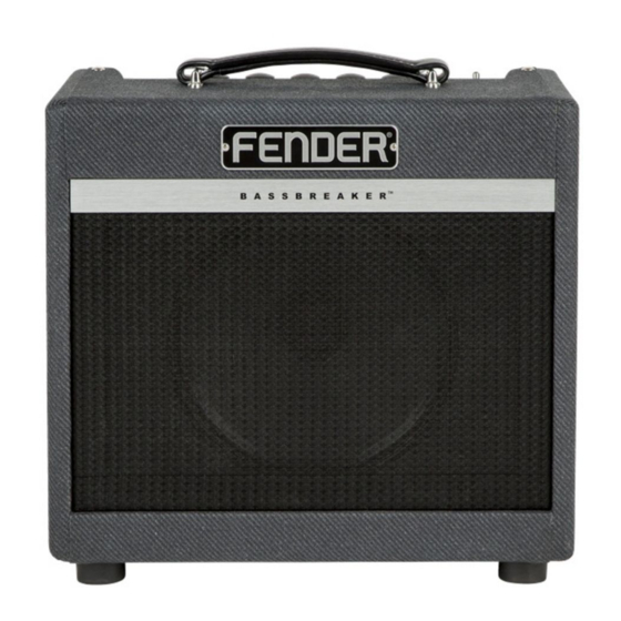
BASSBREAKER™ 007
(This is the model name for warranty claims)
p/n 2262000000 (COMBO 120V)
p/n 2263000000 (HEAD 120V)
SERVICE MANUAL
ATTENTION:
WARRANTY SERVICE PROCEDURES
The Bassbreaker 007 Amplifier is considered to be field serviceable to the component level.
As such stuffed PCB Assemblies are not readily available for this unit. Any Fender Authorized
Service Center in need of a warranty replacement PCB Assembly for this unit should contact
FMIC Tech Support and you will be instructed on how to proceed.
Fender Musical Instruments Corp. / 17600 North Perimeter Drive, Suite 100 / Scottsdale, AZ 85255-5440
Issued October, 2015
Advertisement
Table of Contents

Summary of Contents for Fender BASSBREAKER 007 Combo
- Page 1 The Bassbreaker 007 Amplifier is considered to be field serviceable to the component level. As such stuffed PCB Assemblies are not readily available for this unit. Any Fender Authorized Service Center in need of a warranty replacement PCB Assembly for this unit should contact FMIC Tech Support and you will be instructed on how to proceed.
-
Page 2: Important Notice
This information and any copies produced information contained herein is CONFIDENTIAL electronically or otherwise must be surrendered and PROPRIETARY and is the property of Fender upon demand of Fender Musical Instruments Cor- Musical Instruments Corporation. It is not to be poration. -
Page 3: Specifications
BASSBREAKER™ 007 (This is the model name for warranty claims) SPECIFICATIONS Model Name: BASSBREAKER 007 Combo BASSBREAKER 007 Head Release Number: PR 3032 (Not a model number) Part Numbers (120V, 60Hz) US: 2262000000 COMBOS: (110V, 60Hz) TW: 2262001000 (240V, 50Hz) AUS:... - Page 4 BASSBREAKER™ 007 (This is the model name for warranty claims) Dimensions (Head) Height: 15.81 in (40.02 cm) Width: 8.94 in (37.5 cm) Depth: 8 in (20.3 cm) Weight: 16.6 lbs (8 kg) Product specifications are subject to change without notice...
-
Page 5: Service Notes
BASSBREAKER™ 007 (This is the model name for warranty claims) SERVICE NOTES As modern day amplifiers are more compact mark them to identify their location during reas- and sophisticated proper wire dress becomes a sembly. Clip the four (4) wire ties holding these critical issue, both for the sake of Safety and wires to the anchor holes in the PCB. -
Page 6: Circuit Description
Ohm speaker load. T1’s primary is connected to Note that plate & cathode resistors are non-typical values for Fender tube amps. Its cathode bypass the TUBE PCB and its secondary is connected to cap C27 is switched in and out of the cathode cir- the REAR PANEL PCB. -
Page 7: Power Supply
EL-84 (V3) heat- The Power Supply circuitry is found on the POWER er’s filament only. This secondary is connected to SUPPLY PCB. Its circuitry is typical of a Fender terminals on the TUBE PCB. tube amplifier. The secondary side of the Power... - Page 8 + * Access to this part or assembly is controlled. Please contact the FMIC Customer Service Department. ⚠ Safety Critical Part. Replacement must match Safety Agency –Value, if specified –Type, if specified –Approval Mark(s), if on part. shaded + ⚠ Both a unique Fender® part and a Safety Critical Part as defined above.
- Page 9 + * Access to this part or assembly is controlled. Please contact the FMIC Customer Service Department. ⚠ Safety Critical Part. Replacement must match Safety Agency –Value, if specified –Type, if specified –Approval Mark(s), if on part. shaded + ⚠ Both a unique Fender® part and a Safety Critical Part as defined above.
- Page 10 + * Access to this part or assembly is controlled. Please contact the FMIC Customer Service Department. ⚠ Safety Critical Part. Replacement must match Safety Agency –Value, if specified –Type, if specified –Approval Mark(s), if on part. shaded + ⚠ Both a unique Fender® part and a Safety Critical Part as defined above.
- Page 11 + * Access to this part or assembly is controlled. Please contact the FMIC Customer Service Department. ⚠ Safety Critical Part. Replacement must match Safety Agency –Value, if specified –Type, if specified –Approval Mark(s), if on part. shaded + ⚠ Both a unique Fender® part and a Safety Critical Part as defined above.
- Page 12 + * Access to this part or assembly is controlled. Please contact the FMIC Customer Service Department. ⚠ Safety Critical Part. Replacement must match Safety Agency –Value, if specified –Type, if specified –Approval Mark(s), if on part. shaded + ⚠ Both a unique Fender® part and a Safety Critical Part as defined above.
- Page 13 BASSBREAKER™ 007 (This is the model name for warranty claims) Service Diagram List Service Diagram (Schematic)………………………….….…………..…..Bassbreaker 007 Main PCB Service Diagram (Schematic)…….…………………….…………………Bassbreaker 007 Main PCB Service Diagram (PCB Assembly)………………………………..…………..Bassman 007 Main PCB...
- Page 14 -15.6V -15.8VDC TP10 -15.6V_RP THIS DOCUMENT CONTAINS INFORMATION OF A PROPRIETARY NATURE TO FENDER MUSICAL MUSICAL INSTRUMENTS INSTRUMENTS AND IS SUBMITTED TO YOU IN 7. FOR COMBO: 8. ALL VOLTAGES MEASURED WITH RESPECT TO SP:GROUND USING P35,P36 INSTALLED. JMP5 NOT INSTALLED.
- Page 15 GNDA_RP TABLE 2: TREBLE BOOST FOOTSWITCH CONTROL FOOTSWITCH INTERFACE - REAR PANEL (RP) THIS DOCUMENT CONTAINS INFORMATION OF A PROPRIETARY NATURE TO FENDER MUSICAL MUSICAL INSTRUMENTS INSTRUMENTS AND IS SUBMITTED TO YOU IN CONFIDENCE AND SHALL NOT BE DISCLOSED OR...


