Table of Contents
Advertisement
2019/06/28 22:04:56 (GMT+09:00)
SERVICE MANUAL
Ver. 1.0 2019.06
Name (Model name)
Focal length (mm)
35mm equivalent
focal length*
Lens groups-elements
Angle of view 1*
Angle of view 2*
Minimum focus*
Maximum magnification (×)
Minimum aperture
Filter diameter (mm)
Dimensions
(maximum diameter × height)
(approx., mm (in.))
Mass (approx., g (oz.))
(excluding tripod collar)
SteadyShot
For further information on compatibility with the
tele converter (sold separately) and specifications
used with the tele converter, visit the web site of
Sony in your area, or consult your dealer of Sony or
local authorized service facility of Sony.
Conditions of Use:
(1)
Please use this information only for the purpose of performing repair, maintenance and/or confi guration services of the Sony products (hereinafter the "Repair services") under the
service agreement entered into with the Sony group company (hereinafter the "Service agreement"). Using this information for any purpose other than the purpose described foregoing
is forbidden.
(2)
Only the Authorized Servicer's offi cers, employees or subcontractors (including their offi cers and employees) whose duties justify a need-to-know and who have agreed to hold
confi dential this information (collectively hereinafter the "Permitted users") are permitted to access and use this information. To disclose or disseminate to any person other than the
Permitted users is forbidden.
(3)
Destroy or erase any and all portion of this information promptly in an irrecoverable and secure fashion after achieving the purpose described in Section (1) above.
(4)
Do not copy, replicate, reproduce, alter, translate, transmit, sell, lease, or distribute this information in whole or in part without the prior written permission of the author.
(Notwithstanding foregoing, it is permitted to copy and distribute this information to the Permitted users.)
(5)
Please notify immediately any leakage, loss, theft, misappropriation, or other misuse of this information by e-mail to the following address:
somk-gcs-tissnexim-adm@jp.sony.com
(6)
In addition to the above, the terms and conditions of the Service agreement shall be applied to using this information.
Revision of Information:
This information may be changed or updated at any time without any prior notice. Please confi rm that this information is up-to-date before using it.
9-896-867-11
2019F33-1
©
2019.06
Sony Imaging Products & Solutions Inc.
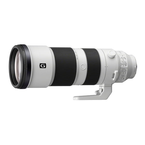
(FE5.6-6.3/200-600 G OSS) (FE 200-600mm F5.6-6.3 G OSS)
SPECIFICATIONS
FE 200-600mm
F5.6-6.3 G OSS
(SEL200600G)
200-600
300-900
1
(mm)
17-24
12°30'-4°10'
2
8°-2°40'
2
(m (feet))
2.4 (7.88)
3
0.2
F32-F36
95
111.5×318
(4 1/2×12 5/8)
2,115 (74.7)
Yes
SEL200600G
This is the equivalent focal length in 35mm format
*
1
when mounted on an Interchangeable Lens Digital
Camera equipped with an APS-C sized image sensor.
2
Angle of view 1 is the value for 35mm cameras, and
*
angle of view 2 is the value for Interchangeable Lens
Digital Cameras equipped with an APS-C sized image
sensor.
3
Minimum focus is the distance from the image
*
sensor to the subject.
• Depending on the lens mechanism, the focal length
may change with any change in shooting distance.
The focal lengths given above assume the lens is
focused at infinity.
Included items
(The number in parentheses indicates the number
of pieces.)
Lens (1), Front lens cap (1), Rear lens cap (1), Tripod
collar (1), Lens hood (1), Lens case (1), Lens strap (1),
Set of printed documentation
Designs and specifications are subject to change
without notice.
and
are trademarks of Sony Corporation.
INTERCHANGEABLE LENS
US Model
Canadian Model
AEP Model
Chinese Model
E-mount
SYS SET
Advertisement
Table of Contents

Related Manuals for Sony E-mount SEL200600G


Summary of Contents for Sony E-mount SEL200600G
- Page 1 Conditions of Use: Please use this information only for the purpose of performing repair, maintenance and/or confi guration services of the Sony products (hereinafter the “Repair services”) under the service agreement entered into with the Sony group company (hereinafter the “Service agreement”). Using this information for any purpose other than the purpose described foregoing is forbidden.
- Page 2 DE FONCTIONNEMENT. NE REMPLACER CES COMPO- • Be sure to control soldering iron tips used for unleaded solder SANTS QUE PAR DES PIÈCES SONY DONT LES NUMÉ- and those for leaded solder so they are managed separately. ROS SONT DONNÉS DANS CE MANUEL OU DANS LES Mixing unleaded solder and leaded solder will cause detach- SUPPLÉMENTS PUBLIÉS PAR SONY.
- Page 3 2019/06/28 22:04:56 (GMT+09:00) SEL200600G 1-5. NOTE ON REPLACEMENT OF MAIN BOARD To replace the Main Board (CL-1065 board), connect the E-mount lens to the ILCE-6300, and read/write of the adjustment data in the following procedure. • Before main board replacement “Read/Write Select” of Lens adjustment program (SEL200600G_ Service_Tool) is set to [Read] to implement the [AjustData- Backup].
- Page 4 2019/06/28 22:04:56 (GMT+09:00) SEL200600G 2. DISASSEMBLY & ASSEMBLY OPERATION NOTES Make sure that the conductive side of a flexible board does not have any stain or foreign materials. Do not touch the conductive side of flexible boards with bare hands. Plug in a flexible board straight, fully into the connector until it reaches the end inside. (Fig. 1, Fig. 2, Fig. 3) (The flexible board was plugged in straight (The flexible board was plugged in (The flexible board was not plugged in...
- Page 5 2019/06/28 22:04:56 (GMT+09:00) SEL200600G 2-1. CONSTITUTION DIAGRAM 1 group piece shaft × 3 1 group piece × 3 Red arrow direction : Shown the front (lens) side cam tube mask ZMR brass coma Black arrow direction : Shown the rear (mount) side 1 group tilt washer ×...
- Page 6 2019/06/28 22:04:56 (GMT+09:00) SEL200600G 2-2. DISASSEMBLY • Disassembled in the order shown in the fl owchart below. 2-2-1. DISASSEMBLY FLOW FRONT SIDE (LENS SIDE) REAR SIDE (MOUNT SIDE) 2-2-2. PROTECT RUBBER 2-2-8. MOUNT BLOCK (Page 2-4) (Page 2-7) 2-2-3. FILTER REINFORCING RING 2-2-9.
- Page 7 2019/06/28 22:04:56 (GMT+09:00) SEL200600G Note: Disassemble in the order indicated by the numbers assigned to the parts in the fi gures such as 1. 2-2-2. PROTECT RUBBER 1 Remove the four convex parts from the groove. 2 Remove the protect rubber from the protect rubber adhesive. groove six protect rubber adhesives groove...
- Page 8 2019/06/28 22:04:56 (GMT+09:00) SEL200600G 2-2-4. FILTER SCREW RING ASSY 1 three screws (2.0 6.0) 2 filter screw ring assy front (lens) side rear (mount) side 2-2-5. B01 ASSY 1 three screws (2.0 6.0) 2 three reinforcing plates 3 B01 assy 4 three 1 group tilt washers Note: Take note of the amount of washers.
- Page 9 2019/06/28 22:04:56 (GMT+09:00) SEL200600G 2-2-6. G03 ASSY 1 three screws (2.0 6.0) 2 three reinforcing plates 3 G03 assy 4 three 1 group tilt washers Note: Take note of the amount of washers. front (lens) side rear (mount) side 2-2-7. CAM TUBE MASK 1 cam tube mask Note: Be careful not to scratch the sheet.
- Page 10 2019/06/28 22:04:56 (GMT+09:00) SEL200600G 2-2-8. MOUNT BLOCK 1 four screws (2.0 6.0) 2 Lift up the mount block. rear shading barrel Note: Take care not to damage the flexible board. tapping screw 4 mount block (1.4 2.5) tapping screw mount block (1.4 2.5) 3 contact block flexible board tapping screw...
- Page 11 2019/06/28 22:04:56 (GMT+09:00) SEL200600G 2-2-10. SW ASSY 3 flexible board 4 SW assy 1 two SW plate screws (L = 4.5 mm) Note 1: If the paint comes off, replace it with a new part without reusing it. 2 Remove the SW assy Note 2: Take care not to damage the flexible board.
- Page 12 2019/06/28 22:04:56 (GMT+09:00) SEL200600G 2-2-12. TRIPOD PLATE 2 tripod plate rear (mount) side 1 four screws (2.0 7.0) front (lens) side SYS SET...
- Page 13 2019/06/28 22:04:56 (GMT+09:00) SEL200600G 2-2-13. TRIPOD RING ASSY 3 tripod sliding piece 2 screw (tripod sliding piece) 3 tripod sliding piece rear (mount) side 2 screw (tripod sliding piece) front (lens) side 3 tripod sliding piece 3 tripod sliding piece 2 screw (tripod sliding piece) 2 screw (tripod sliding piece) 1 Align the holes with the screws while turning the tripod ring assy.
- Page 14 2019/06/28 22:04:56 (GMT+09:00) SEL200600G 2-2-14. TRIPOD RING FITTING TUBE 1 screw (1 group piese) 1 screw (1 group piese) 1 screw (1 group piese) rear (mount) side front (lens) side 2 tripod ring fitting tube 2-11 SYS SET...
- Page 15 2019/06/28 22:04:56 (GMT+09:00) SEL200600G 2-2-15. REAR OUTER TUBE (FRONT) ASSY 1 screw (outer sliding pice) 1 screw (outer sliding pice) rear (mount) side 1 screw (outer sliding pice) front (lens) side 3 rear outer tube (front) assy 2 Rotate the rear outer tube (front) assy fully in the direction of the arrow.
- Page 16 2019/06/28 22:04:56 (GMT+09:00) SEL200600G 2-2-16. F RING FIX BLOCK 1 MF sensor flexible board 2 Peel off the MF sensor flexible board. 4 Rotate the F ring fix block fully in the direction of the arrow. Note: Take care not to damage the flexible board. rear (mount) side 3 screw (1 group piese)
- Page 17 2019/06/28 22:04:56 (GMT+09:00) SEL200600G 2-2-17. MF RING ASSY forcus rubber 1 Rotate the MF ring block to align the six convex parts to the notchs and remove the MF ring block. MF ring block (from rear (mount) side) convex part MF ring assy (total 6 positions) 2 F ring washer rear (mount) side...
- Page 18 2019/06/28 22:04:56 (GMT+09:00) SEL200600G 2-2-18. 6 GROUP ASSY 1 three screws (2.0 6.0) 2 6 group assy three tapping screws (1.4 4.5) G24 metal mask 3 three M2 washers Note: Take note of the amount of washers. 6 group block rear (mount) side front (lens) side 2-2-19.
- Page 19 2019/06/28 22:04:56 (GMT+09:00) SEL200600G 2-2-20. F FRONT RING ASSY 1 three screws (2.0 6.0) 2 F front ring assy front (lens) side rear (mount) side 2-16 SYS SET...
- Page 20 2019/06/28 22:04:56 (GMT+09:00) SEL200600G 2-2-21. REAR TUBE ASSY, 5 GROUP ASSY 3 three tapping screws (1.7 5.0) Note 1: Be careful of the drop of the 5 group block. hole 2 5 group flexible hole board 7 rear tube assy 1 Peel off the graphite sheet. 5 Draw the 5 group flexible board out of the hole.
- Page 21 2019/06/28 22:04:56 (GMT+09:00) SEL200600G 2-2-22. 4 GROUP BLOCK 1 five screws (2.0 6.0) 3 4 group block 2 Move the ZMR flexible board wires to the outer side. rear (mount) side front (lens) side 2-2-23. IRIS, 4 GROUP ASSY 3 three tapping screws (1.7 5.0) 4 iris fix ring assy 7 iris...
- Page 22 2019/06/28 22:04:56 (GMT+09:00) SEL200600G 2-2-24. ZMR ASSY 2 flexible board 3 rib 4 two screws (1 group piese) 5 Lift up the ZMR block. rear (mount) side front (lens) side Note: Take care not to damage 1 Set the Z operation ring to the WIDE position. the flexible board.
- Page 23 2019/06/28 22:04:56 (GMT+09:00) SEL200600G 2-2-25. MIDDLE OUTER TUBE ASSY 3 screw (IB lock piese) 3 screw (IB lock piese) 2 Peel off the flexible board. 3 screw (IB lock piese) 5 middle outer tube assy rear (mount) side Note: Take care not to damage the flexible board.
- Page 24 2019/06/28 22:04:56 (GMT+09:00) SEL200600G 2-2-26. Z OPERATION RING 1 Z operation ring block 2 zoom rubber rear (mount) side front (lens) side 3 Z operation ring 2-21 SYS SET...
- Page 25 2019/06/28 22:04:56 (GMT+09:00) SEL200600G 2-2-27. Z JOINT RING BLOCK 1 screw (1.7 5.0) • The Z joint ring block can be disassembled as shown in the figure below. 2 Z joint piece frictin sheet A Note: The frictin sheet A cannot be reused. Be sure to replace them with new parts.
- Page 26 2019/06/28 22:04:56 (GMT+09:00) SEL200600G 2-2-28. FRONT OUTER TUBE ASSY 1 six tapping screws (1.7 5.0) 2 front outer tube assy front (lens) side rear (mount) side 3 Z ring washer rear (mount) side front (lens) side 2-23 SYS SET...
- Page 27 2019/06/28 22:04:56 (GMT+09:00) SEL200600G 2-2-29. 2 GROUP ASSY 1 Set the vertical slit tube assy to the TELE position. 4 tapping screw (1.7 8.0) 5 2 group piece block 2nd coma shaft 3 sub coma 2 group piece 2 tapping screw (1.7 5.0) 4 tapping screw (1.7 8.0)
- Page 28 2019/06/28 22:04:56 (GMT+09:00) SEL200600G 2-2-30. 3 GROUP BLOCK, VERTICAL SLIT TUBE ASSY 1 Set the vertical slit tube assy to the TELE position. front (lens) side rear (mount) side 5 3 group piece block 5 3 group piece block 4 tapping screw (1.7 9.0) 4 tapping screw...
- Page 29 2019/06/28 22:04:56 (GMT+09:00) SEL200600G 2-3. ASSEMBLY • Assemble in the order shown in the fl owchart below. 2-3-1. ASSEMBLY FLOW VERTICAL SLIT TUBE ASSY 2-3-2. 3 GROUP ASSY (Page 2-27) 2-3-3. 2 GROUP ASSY (Page 2-28) 2-3-15. 6 GROUP ASSY (Page 2-39) 2-3-4.
- Page 30 2019/06/28 22:04:56 (GMT+09:00) SEL200600G Assemble in the order indicated by the numbers assigned to the parts in the fi gures such as 1. Note: 2-3-2. 3 GROUP ASSY 2 Paste in the center of the G10 mask. rear (mount) side 3 group block marking front (lens) side 1 3 group assy...
- Page 31 2019/06/28 22:04:56 (GMT+09:00) SEL200600G 2-3-3. 2 GROUP ASSY 2 Align the marking to the long hole position and install the 2 group assy. marking long hole 1 Set the vertical slit tube assy to the TELE position. notch front (lens) side rear (mount) side 6 tapping screw (1.7 8.0) 4 three 2nd coma shafts...
- Page 32 2019/06/28 22:04:56 (GMT+09:00) SEL200600G 2-3-4. FRONT OUTER TUBE ASSY 3 Align the rib to the notch position and install the front outer tube assy. 2 Z ring washer Note 1: When replacing the Z ring washer, choose parts that do not cause backlash. Note 2: Apply grease to all surfaces.
- Page 33 2019/06/28 22:04:56 (GMT+09:00) SEL200600G 2-3-5. 1 GROUP PIECE 4 1 group piece block rear (mount) side 1 Set the vertical slit tube assy to the TELE position. front (lens) side 3 three 1 group piece shafts 4 1 group piece block 2 three 1 group pieces Note 1: When replacing the 1 group piece, choose parts that do not cause backlash and confirm...
- Page 34 2019/06/28 22:04:56 (GMT+09:00) SEL200600G 2-3-6. Z JOINT RING 3 frictin sheet A Note 1: The frictin sheet A cannot be reused. Be sure to replace them with new parts. 2 Apply grease to six places. FT410 2 Apply grease to three places. 2 Apply grease to two places.
- Page 35 2019/06/28 22:04:56 (GMT+09:00) SEL200600G 2-3-7. Z OPERATION RING 2 Apply grease all around. 2 Apply grease to three places. G-85 G-85 front (lens) side rear (mount) side rear (mount) side front (lens) side 1 Z operation ring 2 Apply grease to six places. G-85 3 Apply grease all around.
- Page 36 2019/06/28 22:04:56 (GMT+09:00) SEL200600G 2-3-8. MIDDLE OUTER TUBE ASSY 2 Align the index to the “300” and install the middle outer tube assy. Note: Take care not to damage the flexible board. index rear (mount) side front (lens) side “300” 3 Rotate the middle outer tube assy in the direction of the arrow and align the index to the “200”.
- Page 37 2019/06/28 22:04:56 (GMT+09:00) SEL200600G 2-3-9. ZMR ASSY 5 Insert the ZMR brass coma to the cam groove, and install the ZMR block. ZMR brass coma 3 Move the ZMR slider to front (lens) side. 1 ZMR assy rear (mount) side front (lens) side rear (mount) side cam groove 2 ZMR brass coma...
- Page 38 2019/06/28 22:04:56 (GMT+09:00) SEL200600G 2-3-10. IRIS 8 three tapping screws (1.7 5.0) 6 iris fix ring assy 3 Crease the iris flexible board. : Mountain fold : Valley fold 2 iris 5 Install the iris. 4 Pass the iris flexible board through the hole. Note: Take care not to damage the flexible board.
- Page 39 2019/06/28 22:04:56 (GMT+09:00) SEL200600G 2-3-11. 4 GROUP BLOCK 4 five screws (2.0 6.0) 4 group block (from rear (mount) side) 3 boss 2 Align the marking to the index and install the 4 group block. marking Note: Take care so that the flexible board is not pinched.
- Page 40 2019/06/28 22:04:56 (GMT+09:00) SEL200600G 2-3-12. 5 GROUP ASSY 2 Remove the shaded release paper from the graphite sheet. 3 Paste the graphite sheet. 1 5 group assy Note 1: The graphite sheet cannot be reused. Be sure to replace them with new parts. Note 2: Paste only the yellow frame part.
- Page 41 2019/06/28 22:04:56 (GMT+09:00) SEL200600G 2-3-13. F FRONT RING ASSY 3 three screws (2.0 6.0) 2 boss 2 boss 1 F front ring assy front (lens) side rear (mount) side 2-3-14. REAR TUBE BLOCK 5 five screws (2.0 6.0) 0 Connect the ZMR flexible board. 8 Fit the ZMR flexible board on the groove.
- Page 42 2019/06/28 22:04:56 (GMT+09:00) SEL200600G 2-3-15. 6 GROUP ASSY 4 three tapping screws (1.4 4.5) 2 G24 metal mask rear (mount) side front (lens) side 3 boss 3 boss 1 6 group block 7 three screws (2.0 6.0) groove 6 group assy (from rear (mount) side) 6 Align the groove to the screw hole and install the 6 group assy.
- Page 43 2019/06/28 22:04:56 (GMT+09:00) SEL200600G 2-3-16. F RING WASHER 2 F ring washer Note 1: When replacing the F ring washer, choose parts that do not cause backlash. Note 2: Apply grease to all surfaces. MG1087 rear (mount) side 1 Apply grease to six places of the rear tube assy. front (lens) side MG1087 1 Apply grease to eight places of the rear tube assy.
- Page 44 2019/06/28 22:04:56 (GMT+09:00) SEL200600G 2-3-17. MF RING ASSY 3 forcus rubber 2 Apply grease all around. MG1087 1 MF ring assy front (lens) side rear (mount) side rear (mount) side Note 1: Do not attach grease to the reflective ring. front (lens) side 5 Align the six convex parts to the notchs and install the MF ring block.
- Page 45 2019/06/28 22:04:56 (GMT+09:00) SEL200600G 2-3-18. F RING FIX ASSY 5 Align the F ring fix block with the position of the figure. F ring fix block ribs (from rear (mount) side) (total 3 positions) MF sensor flexible board 2 MF sensor assy 3 two bosses rear (mount) side F ring fix block...
- Page 46 2019/06/28 22:04:56 (GMT+09:00) SEL200600G 2-3-19. REAR OUTER TUBE (FRONT) ASSY 2 Install the rear outer tube (front) assy. no index 1 Align the rear outer tube (front) assy with the position of the figure. notch index with index index index with index with index front (lens) side index...
- Page 47 2019/06/28 22:04:56 (GMT+09:00) SEL200600G 2-3-20. TRIPOD RING FITTING TUBE 1 Align the groove with the position of the figure and install the tripod ring fitting tube. groove tripod ring fitting tube rear (mount) side front (lens) side index 2 screw (1 group piese) 2 screw (1 group piese) 3 adhesive bond...
- Page 48 2019/06/28 22:04:56 (GMT+09:00) SEL200600G 2-3-21. TRIPOD KNOB 2 Apply grease all around. OS-20HF rear (mount) side rear (mount) side front (lens) side front (lens) side 3 Apply grease all around. 1 tripod ring block FT410 front (lens) side rear (mount) side 4 Apply grease all around. 5 Apply grease all around.
- Page 49 2019/06/28 22:04:56 (GMT+09:00) SEL200600G 2-3-22. TRIPOD RING ASSY 4 tripod ring assy 1 Apply grease all around. FT410 2 Apply grease all around. G-62 front (lens) side 3 Apply grease all around. G-48 6 tripod sliding piece 7 screw (tripod sliding piece) Note: Apply the adhesive bond to 6 tripod sliding the tip of screws.
- Page 50 2019/06/28 22:04:56 (GMT+09:00) SEL200600G 2-3-23. TRIPOD PLATE 2 four screws (2.0 7.0) Note: Apply the adhesive bond to the tip of screws. B-40 2-47 SYS SET...
- Page 51 2019/06/28 22:04:56 (GMT+09:00) SEL200600G 2-3-24. REAR OUTER RING ASSY 3 tapping screw (1.4 3.5) 3 tapping screw (1.4 3.5) 2 rear outer conductin plate Note: Be careful not to deform it. 2 rear outer conductin plate Note: Be careful not to deform it. 1 rear outer ring assy front (lens) side rear (mount) side...
- Page 52 2019/06/28 22:04:56 (GMT+09:00) SEL200600G 2-3-25. SW ASSY 2 Connect the flexible board. 1 SW assy 4 two SW plate screws (L = 4.5 mm) Note: If the paint comes off, replace it with 3 Install the SW assy. a new part without reusing it. rear (mount) side front (lens) side 2-49...
- Page 53 2019/06/28 22:04:56 (GMT+09:00) SEL200600G 2-3-26. CL-1065 BOARD 1 CL-1065 board 2 two flexible boards rear (mount) side front (lens) side 5 three screws (PC board) 5 four screws (PC board) 4 two bosses rear outer ring assy rear tube assy rear outer ring assy rear tube assy 3 Arrange the flexible board in the space 3 Arrange the flexible board in the space...
- Page 54 2019/06/28 22:04:56 (GMT+09:00) SEL200600G 2-3-27. CONTACT BLOCK ASSY, MOUNT WATERPROOF RUBBER 5 rear shading barrel rear (mount) side front (lens) side 6 tapping screw (1.4 2.5) 1 mount block 6 tapping screw (1.4 2.5) 6 tapping screw (1.4 2.5) 4 tapping screw (1.4 2.5) 2 contact block assy...
- Page 55 2019/06/28 22:04:56 (GMT+09:00) SEL200600G 2-3-29. CAM TUBE MASK 1 cam tube mask Note: Be careful not to scratch the sheet. : guide line cam tube mask front (lens) side (from front (lens) side) rear (mount) side 2-52 SYS SET...
- Page 56 2019/06/28 22:04:56 (GMT+09:00) SEL200600G 2-3-30. G03 ASSY 3 Temporarily fasten the three screws (2.0 6.0). reinforcing plate front (lens) side 2 three reinforcing plates rear (mount) side rounded side face marking 1 Align the marking with the index and install the G03 assy. 5 Tighten the three screws (2.0 6.0).
- Page 57 2019/06/28 22:04:56 (GMT+09:00) SEL200600G 2-3-31. B01 ASSY 3 Temporarily fasten the three screws (2.0 6.0). reinforcing plate front (lens) side rear (mount) side 2 three reinforcing plates rounded side face 1 Align the boss with the index and install the B01 assy. boss 5 Tighten the three screws (2.0 6.0).
- Page 58 2019/06/28 22:04:56 (GMT+09:00) SEL200600G 2-3-32. FILTER SCREW RING ASSY 2 three screws (2.0 6.0) 1 Align the index and install the filter screw ring assy. index front (lens) side index rear (mount) side 2-3-33. FILTER REINFORCING RING 1 Align the notch to the position in the figure and install the filter reinforcing ring. 2 four screws (reinforcing ring piece) notch...
- Page 59 2019/06/28 22:04:56 (GMT+09:00) SEL200600G 2-3-34. PROTECT RUBBER 2 Insert the four convex parts into the groove and install the protect rubber. convex part convex part convex part convex part groove 1 six protect rubber adhesives groove groove groove front (lens) side rear (mount) side filter reinforcing ring (from front (lens) side) 4 Push the lens barrel from the mount side...
- Page 60 2019/06/28 22:04:56 (GMT+09:00) SEL200600G 3. EXPLODED VIEWS Note: • -XX and -X mean standardized parts, so they may have some diff erence from the original one. • Items marked “*” are not stocked since they are seldom required for routine service. Some delay should be anticipated when ordering these items.
- Page 61 2019/06/28 22:04:56 (GMT+09:00) SEL200600G 3-2. MOUNT SECTION Red arrow direction : Shown the front (lens) side Black arrow direction : Shown the rear (mount) side Refer to 4 group block section. not supplied not supplied not supplied not supplied not supplied not supplied not supplied Ref.
- Page 62 2019/06/28 22:04:56 (GMT+09:00) SEL200600G 3-3. 4 GROUP BLOCK SECTION Red arrow direction : Shown the front (lens) side Black arrow direction : Shown the rear (mount) side Refer to middle outer tube section. (Note 2) not supplied not supplied Refer to rear tube section. (Note 1) not supplied not supplied...
- Page 63 2019/06/28 22:04:56 (GMT+09:00) SEL200600G 3-4. REAR TUBE SECTION Red arrow direction : Shown the front (lens) side Black arrow direction : Shown the rear (mount) side (Note 2) (Note 1) (Note 1) not supplied Note 1: This part is for adjustment. Refer to “3-7. SELECTION PARTS”, and adjust the thickness by following the results of the check.
- Page 64 2019/06/28 22:04:56 (GMT+09:00) SEL200600G 3-5. MIDDLE OUTER TUBE SECTION Red arrow direction : Shown the front (lens) side Black arrow direction : Shown the rear (mount) side Refer to vertical slit tube section. (Note 2) (Note 2) (Note 2) (Note 2) (Note 2) (Note 1) (Note 2) (Note 1)
- Page 65 2019/06/28 22:04:56 (GMT+09:00) SEL200600G 3-6. VERTICAL SLIT TUBE SECTION Red arrow direction : Shown the front (lens) side Black arrow direction : Shown the rear (mount) side (Note) (Note) (Note) (Note) (Note) (Note) (Note) (Note) (Note) (Note) (Note) (Note) (Note) (Note) (Note) (Note) (Note) (Note)
- Page 66 2019/06/28 22:04:56 (GMT+09:00) SEL200600G 3-7. SELECTION PARTS Ref. No. 9 1 GROUP TILT WASHER Ref. No. 155 M2 WASHER This part is for adjustment. This part is for adjustment. Adjust the thickness by following the results of the check. Adjust the thickness by following the results of the check. Thickness (mm) Part No.
- Page 67 2019/06/28 22:04:56 (GMT+09:00) SEL200600G Ref. No. 210 Z RING WASHER Ref. No. 215 1 GROUP PIECE Perform an operation check of the relevant locations, and select an Perform an operation check of the relevant locations, and select an appropriate part. appropriate part. D1 (mm) D2 (mm) Part No.
- Page 68 2019/06/28 22:04:56 (GMT+09:00) SEL200600G Ref. No. 254 3RD COMA SHAFT Ref. No. 258 2ND COMA SHAFT Perform an operation check of the relevant locations, and select an Perform an operation check of the relevant locations, and select an appropriate part. appropriate part. ø...
- Page 69 2019/06/28 22:04:56 (GMT+09:00) SEL200600G 4. SUPPLIED ACCESSORIES Note: • Items marked “*” are not stocked since they are seldom required for routine service. Some delay should be anticipated when ordering these items. Ref. No. Part No. Description 500356501 MANUAL, INSTRUCTION (JAPANESE, ENGLISH, FRENCH, SPANISH, SIMPLIFIED CHINESE) 500356511 MANUAL, INSTRUCTION...
- Page 70 2019/06/28 22:04:56 (GMT+09:00) SEL200600G 5. ADJUSTMENTS Note: When disassembled the lens, after the assembly has been completed, perform adjustments by referring to this chapter. 5-1. BEFORE STARTING ADJUSTMENTS 5-1-1. Adjustment Items after Replacing Parts When replacing main parts and boards, adjust or check the items indicated by z in the following table. Note: Do not adjust the items indicated by .
- Page 71 2019/06/28 22:04:56 (GMT+09:00) SEL200600G 5-1-2. Adjustment/Check Procedure Flow Chart After the parts replacement Lens adjustment program 5-5. SEL200600G_ (1) PRESET ADJ Service_Tool Zoom: Wide 5-2-3. Optical axis 5-2-2. Optical axis adjustment check (B06 farame assy) 5-4-1. Partial blur 5-3. Resolving power 5-3. Resolving power adjustment check (Note) check (Note)
- Page 72 2019/06/28 22:04:56 (GMT+09:00) SEL200600G 5-1-3. List of Service Tools and Equipment Service Tools/Equipments Part No. Fig. No. Remarks ServiceAppLauncher_Ver[][][].zip Version: 1.0.1 or higher ServiceAppLauncher ― ― Following a Excel file is stored in “C:\Service\ErrorCodeList” folder of the C drive. • ErrorCodeList.xlsx SEL200600G_Ver[][][].zip Version: 1.0.0 or higher Lens adjustment program Following two Excel files are stored in “C:\Service\FSA\SEL200600G_...
- Page 73 2019/06/28 22:04:56 (GMT+09:00) SEL200600G Service Tools/Equipments Part No. Fig. No. Remarks 1-487-963-12 Except US, Canadian AC adaptor (AC-PW20) 1-487-963-22 US, Canadian Infinity jig (1000 mm) J-6082-747-A FB adjustment chart (4.53 mm) J-6082-848-A For “Infinity jig (1000 mm)”. J-6082-604-A 110V 1000 mm Collimator J-6082-604-B 240V Flange back tester...
- Page 74 2019/06/28 22:04:56 (GMT+09:00) SEL200600G Service Tools/Equipments Part No. Fig. No. Remarks For optical axis adjustment (B06 frame assy) For partial blur adjustment (B06 frame assy) Optical axis adjustment spring ― ― Use three optical axis adjustment spring. (refer to “5-1-4. Preparation of optical axis adjustment spring”) For optical axis adjustment (B06 frame assy) Optical axis adjustment pin J-6082-897-A...
- Page 75 2019/06/28 22:04:56 (GMT+09:00) SEL200600G 5-2. OPTICAL AXIS CHECK/ Setting of the Flange Back Tester 1. Set the equipment as shown in the following figure. ADJUSTMENT Dial Gauge A-mount attachment (Min. scale: 0.01 mm) 5-2-1. Setting/Preparation of the Flange Back (f’F) Objective lens (10x) Measuring Instrument Eyepiece lens (7x) Equipment and Tools (Common)
- Page 76 2019/06/28 22:04:56 (GMT+09:00) SEL200600G Preparations of Using a Camera (General E-mount Preparations of Using a B-L Control Box Interchangeable Lens Digital Camera) Equipment and Tools • Personal Computer (See Note 1) Equipment and Tools • B-L Control Box (Supplied with D-sub 15-pin cable) •...
- Page 77 2019/06/28 22:04:56 (GMT+09:00) SEL200600G 5. When starting and finishing the BLG-TestProgram, perform the following procedure. • Starting the BLG-TestProgram • Finishing the BLG-TestProgram Procedure of Starting Procedure of Finishing (1) Mount a checking lens to the lens mount block. (1) Click [Power] to turn off the power to the lens. (2) Connect the D-sub 15-pin cable to the lens mount block, and (2) Confirm that the two LEDs on the B-L Control Box are not lit.
- Page 78 2019/06/28 22:04:56 (GMT+09:00) SEL200600G 6. Start the lens adjustment program “BLG-TestProgramV[][][].exe”. 7. When [Open] is clicked and communication between personal computer and B-L Control Box is connected, the button name changes to [Close] and the [Power] button is made active. 8. Click [Power] to supply power to the checking lens. At this time, confirm that both of the two LEDs on the B-L Control Box are light.
- Page 79 2019/06/28 22:04:56 (GMT+09:00) SEL200600G 10. Align the plane mirror with the center projected image on the screen, and confirm again that the reflected light illuminates the center of the checking lens. If the reflected light position is deviated, re-adjust the lens projector position. 11.
- Page 80 2019/06/28 22:04:56 (GMT+09:00) SEL200600G 5-2-2. Optical Axis Check 5-2-3. Optical Axis Adjustment (B06 frame assy) Checking Procedure Note: Optical Axis Adjustment (B06 frame assy) is done by increasing 1. Adjust the optical axis while observing the microscope until the or decreasing the thickness of the washer. Refer to “2-2.
- Page 81 2019/06/28 22:04:56 (GMT+09:00) SEL200600G 4. Insert the optical axis adjustment pin in the position shown below B06 FRAME WASHER (2 places) until it stops. Thickness (mm) Part No. 0.02 500835201 0.03 500835211 0.05 500835221 0.08 500835231 0.10 500835241 0.15 500835251 0.20 500835261 5.
- Page 82 2019/06/28 22:04:56 (GMT+09:00) SEL200600G 1 GROUP TILT WASHER 5-2-4. Optical Axis Adjustment (B01 assy) Note: Optical Axis Adjustment (B01 assy) is done by increasing or decreasing the thickness of the washer. Thickness (mm) Part No. Refer to “2-2. DISASSEMBLY”, disassemble the lens, and 0.02 500578601 change the thickness of the washer.
- Page 83 2019/06/28 22:04:56 (GMT+09:00) SEL200600G 5-3. RESOLVING POWER CHECK 5-3-1. Setting/Preparation of the Lens Test Projector Preparations of Using a Camera (General E-mount Interchangeable Lens Digital Camera) Equipment and Tools • Camera (General E-mount interchangeable lens digital camera) • Lens Test Projector (F) •...
- Page 84 2019/06/28 22:04:56 (GMT+09:00) SEL200600G Preparations of Using a B-L Control Box Equipment and Tools • Personal Computer (See Note 1) • B-L Control Box (Supplied with D-sub 15-pin cable) • AC cable (Sold on the market) • RS-232C Cable (D-sub 9-pin (Male with securing screws), D-sub 9-pin (Female with securing screws)) Straight type (Sold on the market) •...
- Page 85 2019/06/28 22:04:56 (GMT+09:00) SEL200600G (2) Starting and Finishing the BLG-TestProgram Starting the BLG-TestProgram Procedure of Finishing 1. Mount a checking lens to the lens mount block. 1. Click [Power] to turn off the power to the lens. 2. Connect the D-sub 15-pin cable to the lens mount block, and 2.
- Page 86 2019/06/28 22:04:56 (GMT+09:00) SEL200600G (3) Setting Method Setting Procedure 1. Start the lens adjustment program “BLG-TestProgramV[][][].exe”. 2. When [Open] is clicked and communication between personal computer and B-L Control Box is connected, the button name changes to [Close] and the [Power] button is made active. 3.
- Page 87 2019/06/28 22:04:56 (GMT+09:00) SEL200600G 5. Align the plane mirror with the center projected image on the screen, and confirm again that the reflected light illuminates the center of the checking lens. If the reflected light position is deviated, re-adjust the lens projector position. 6.
- Page 88 2019/06/28 22:04:56 (GMT+09:00) SEL200600G 9. Clicking [Focus(Target Dist.)] displays the focus JOG operation window. Focus position indicator Select focus step value Select and enter focus step speed Focus drive Focus drive (near) (far) 10. Adjust the focus position with [Near] and [Far] while selecting “Focus Step” and “Low”/“Mid”/“High”, and then click [OK] to close the focus JOG window.
- Page 89 2019/06/28 22:04:56 (GMT+09:00) SEL200600G 5-3-2. Projective Resolving Power Check Reference value: Number of projective resolving power lines (lines/mm) Focal length f Distance (m) (mm) Peripheral (y' = 15) Peripheral (y' = 18) Center (y' = 0) 10.0 12.0 More than More than More than More than More than...
- Page 90 2019/06/28 22:04:56 (GMT+09:00) SEL200600G 4. Read the value of the number of projective resolving power lines (maximum resolving power) of the center projected image (y’ = 0). 5. Read the value (the number of projective resolving power lines) of the thinnest line (resolution limit) that allows recognition of contrast of the sagittal (S) image and meridional (M) image (three lines) of the peripheral projected image (y’...
- Page 91 2019/06/28 22:04:56 (GMT+09:00) SEL200600G 5-3-3. Photographic Resolving Power Check For this lens, it is necessary to check the photographic resolving power with two kinds of focal length (200 mm, 600 mm). Therefore, please check with the case where the zoom set to the WIDE end (focal length: 200 mm) and the case where it is set to the TELE end (focal length: 600 mm).
- Page 92 2019/06/28 22:04:56 (GMT+09:00) SEL200600G 6. Apply the adhesive bond (B-110) to the following 3 places. 5-4. RESOLVING POWER ADJUSTMENT Note 3: Apply a bond to the 3 places of the B06 frame assy when 5-4-1. Partial Blur Adjustment (B06 frame assy) all optical adjustments are complete. Note 1: Partial Blur Adjustment (B06 frame assy) is done by moving B-110 B-110...
- Page 93 2019/06/28 22:04:56 (GMT+09:00) SEL200600G 5-4-2. Partial Blur Adjustment (6 group assy) 5-4-3. Partial Blur Adjustment (G03 assy) Note: Partial Blur Adjustment (6 group assy) is done by increasing or Note: Partial Blur Adjustment (G03 assy) is done by increasing or de- decreasing the thickness of the washer. creasing the thickness of the washer.
- Page 94 2019/06/28 22:04:56 (GMT+09:00) SEL200600G 5-5. SEL200600G_Service_Tool 5-5-1. Preparations Set the equipment and the checking lens as shown below. Equipment and Tools When the subject is a small pattern box • Personal Computer (See Note 1, 2) • HASP key (SeusEX) Small pattern box (PTB-1450) •...
- Page 95 2019/06/28 22:04:56 (GMT+09:00) SEL200600G 5. The installer confirm screen appears, then click the [Next] button (1) Installation of ServiceAppLauncher to start the installation. Prepare a version 1.0.1 or higher of the ServiceAppLauncher. Note: Perform the installation by administrator privileges. Do not change the installation folder. Procedure of Installation 1.
- Page 96 2019/06/28 22:04:56 (GMT+09:00) SEL200600G 5. The installer confirm screen appears, then click the [Next] button (2) Installation of EEPROM_LogVewer to start the installation. Prepare a version 1.0.0 or higher of the EEPROM_LogVewer. Note: Perform the installation by administrator privileges. Do not change the installation folder. Procedure of Installation 1.
- Page 97 2019/06/28 22:04:56 (GMT+09:00) SEL200600G 5. The installer confirm screen appears, then click the [Next] button (3) Installation of SEL200600G_Service_Tool to start the installation. Prepare a version 1.0.0 or higher of the SEL200600G_Service_Tool. Note: Perform the installation by administrator privileges. Do not change the installation folder. Procedure of Installation 1.
- Page 98 2019/06/28 22:04:56 (GMT+09:00) SEL200600G 5-5-2. Precautions for Use 5-5-3. Method of Starting and Finishing Make sure to disconnect the AC adaptor after finishing the adjustment (including the case when stops due to an error). • When the instruction “PUSH ENTER” as shown below is displayed SeusEX will start when the SEL200600G_Service_Tool is started.
- Page 99 2019/06/28 22:04:56 (GMT+09:00) SEL200600G 5-5-4. Adjustment Method of Each Item Adjusting Method 1. Click the [PRESET ADJ] button in the Adjustment and Inspec- tion. (1) PRESET ADJ 2. Since get of the zoom end AD value is started, operate the zoom- • Get the zoom end AD value. ing ring accordance with the message.
- Page 100 2019/06/28 22:04:56 (GMT+09:00) SEL200600G 4. Message screen is displayed in the following order. Operate the 6. Message screen is displayed in the following order. Operate the focus-mode switch in accordance with the message. SteadyShot switch in accordance with the message. Focus-mode switch SteadyShot switch 7.
- Page 101 2019/06/28 22:04:56 (GMT+09:00) SEL200600G 9. Set for the focusing ring to the position of the tape etc. stuck by 16. When the automatic adjustment is completed, message screen is “Preparations”. displayed in the following. Use a tripod to set the lens in a stable horizontal condition.
- Page 102 2019/06/28 22:04:56 (GMT+09:00) SEL200600G 20. When the ENTER key is pressed, message screen is displayed (2) PRESET2 ADJ in the following. Set the zooming ring to the TELE end (focal • Perform focus actuator inspection. length: 600 mm). Subject Not required Operation on Lens side Not required Shooting Mode of the camera P mode (Program Auto) Adjusting Method...
- Page 103 2019/06/28 22:04:56 (GMT+09:00) SEL200600G 4. “When the focus lens stops, press the Enter button.” is displayed, (3) F NO ADJ confirm that the screen is fully white and press the ENTER key. • Adjust the F number. Small pattern box (PTB-1450) Subject + Clear chart •...
- Page 104 2019/06/28 22:04:56 (GMT+09:00) SEL200600G 4. “PLEASE CHANGE TO - WIDE” is displayed, set the zooming (4) FB ADJ ring to the WIDE end (focal length: 200 mm). • Adjust the flange back of inner focus lens. Infinity jig (1000 mm) Subject + FB adjustment chart (4.53 mm) •...
- Page 105 2019/06/28 22:04:56 (GMT+09:00) SEL200600G 8. After the automatic adjustment of TELE end is completed, mes- 13. After the automatic adjustment of POS8 is completed, message sage screen is displayed in the following. Set the zooming ring screen is displayed in the following. Set the zooming ring to the to the WIDE end (focal length: 200 mm).
- Page 106 2019/06/28 22:04:56 (GMT+09:00) SEL200600G 4. When the ENTER key is pressed, focus position compensation (5) FPCA adjustment is started. • The position error for each speed of the focus lens is corrected. Infinity jig (1000 mm) Subject + FB adjustment chart (4.53 mm) Operation on Lens side •...
- Page 107 2019/06/28 22:04:56 (GMT+09:00) SEL200600G 3. “Select the AF.” is displayed, set the focus-mode switch to the (6) Focus Shift Adjustment • The focus shift due to change in the F number is corrected. • Infinity jig (1000 mm) + FB Subject adjustment chart (4.53 mm) •...
- Page 108 2019/06/28 22:04:56 (GMT+09:00) SEL200600G 9. After the automatic adjustment is completed, message screen is 14. After the automatic adjustment is completed, the calculation displayed in the following. Set the infinity jig (1000 mm). processing of the quantity of correction is started. The display of the message screen changes as follows.
- Page 109 2019/06/28 22:04:56 (GMT+09:00) SEL200600G 4. “Confirm the image is in focus while zoom. Start” is displayed, (7) FB CHK press the ENTER key. • Check the focus position. Infinity jig (1000 mm) Subject + FB adjustment chart (4.53 mm) • Focus-mode switch Operation on Lens side •...
- Page 110 2019/06/28 22:04:56 (GMT+09:00) SEL200600G (8) ROM CHECK (9) SLEEP • Check the data stored on the Main Board. • Set the switch to initial position. • Perform final check. Subject Not required Subject Not required Operation on Lens side Not required • Focus-mode switch Shooting Mode of the camera P mode (Program Auto) •...
- Page 111 2019/06/28 22:04:56 (GMT+09:00) SEL200600G (10) Write the serial number (11) Check the log information • Write the lens serial number on the Main board. • It can save/check the log information of the Main board. Subject Not required Subject Not required Operation on Lens side Not required Operation on Lens side Not required...
- Page 112 2019/06/28 22:04:56 (GMT+09:00) SEL200600G Revision History Ver. Date History Contents 2019.06 Official Release — SYS SET...