Table of Contents
Advertisement
Quick Links
CONTENTS
SAFETY CONSIDERATIONS . . . . . . . . . . . . . . . . . . . 1
GENERAL . . . . . . . . . . . . . . . . . . . . . . . . . . . . . . . . . . . 2
INSTALLATION . . . . . . . . . . . . . . . . . . . . . . . . . . . . . . 4
Step 1 - Complete Pre-Installation Checks . . . . . . . 4
Step 2 - Rig and Place Unit . . . . . . . . . . . . . . . . . . . 4
Step 3 - Complete Refrigerant Piping . . . . . . . . . . . 4
Step 4 - Install Ductwork . . . . . . . . . . . . . . . . . . . . . 5
Step 5 - Insulate the Unit . . . . . . . . . . . . . . . . . . . . . 5
Step 6 - Complete Electrical Connections . . . . . . . 7
START-UP . . . . . . . . . . . . . . . . . . . . . . . . . . . . . . . . . . 8
General . . . . . . . . . . . . . . . . . . . . . . . . . . . . . . . . . . . . . 8
System Evacuation and Dehydration . . . . . . . . . . . . 8
Charging Procedure . . . . . . . . . . . . . . . . . . . . . . . . . . 8
Low Ambient Operation (Factory Installed) . . . . . . . 8
(Field Installation) . . . . . . . . . . . . . . . . . . . . . . . . . . 8
Controls and Rotation of Fans . . . . . . . . . . . . . . . 8
Adjust Fan Speed . . . . . . . . . . . . . . . . . . . . . . . . . . . . 8
SERVICE . . . . . . . . . . . . . . . . . . . . . . . . . . . . . . . . . . 14
Cleaning Condenser Coils . . . . . . . . . . . . . . . . . . . . 14
Lubrication . . . . . . . . . . . . . . . . . . . . . . . . . . . . . . . . . 14
Condenser Fan Adjustment . . . . . . . . . . . . . . . . . . . 14
Pulley Alignment . . . . . . . . . . . . . . . . . . . . . . . . . . . . 15
Belt Tension Adjustment . . . . . . . . . . . . . . . . . . . . . 15
Changing Fan Wheel . . . . . . . . . . . . . . . . . . . . . . . . . 15
Fan Bearing Replacement . . . . . . . . . . . . . . . . . . . . 15
Concentric Alignment . . . . . . . . . . . . . . . . . . . . . . . . 15
Condenser Motor Starter Setting (after Lockout/
Tagout) . . . . . . . . . . . . . . . . . . . . . . . . . . . . . . . . . . 15
MAINTENANCE . . . . . . . . . . . . . . . . . . . . . . . . . . . . . 16
Cleaning . . . . . . . . . . . . . . . . . . . . . . . . . . . . . . . . . . . 16
Inspection . . . . . . . . . . . . . . . . . . . . . . . . . . . . . . . . . 16
Air Filters . . . . . . . . . . . . . . . . . . . . . . . . . . . . . . . . . . 16
TROUBLESHOOTING . . . . . . . . . . . . . . . . . . . . . . . . 16
START-UP CHECKLIST . . . . . . . . . . . . . . . . . . . . . CL-1
SAFETY CONSIDERATIONS
Installing, starting up, and servicing air-conditioning components
and equipment can be dangerous. Only trained, qualified installers
and service mechanics should install, start up, and service this
equipment.
Manufacturer reserves the right to discontinue, or change at any time, specifications or designs without notice and without incurring obligations.
Catalog No. 04-53090029-01
Installation, Start-Up and
Service Instructions
Printed in U.S.A.
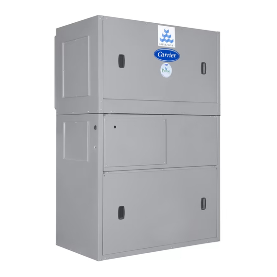
Remote Air-Cooled Condenser Units
When working on the equipment, observe precautions in the liter-
ature and on tags, stickers, and labels attached to the equipment.
Page
Follow all safety codes. Wear safety glasses and work gloves.
.
Electrical shock can cause personal injury and death. Shut off
all power to this equipment during installation. There may be
more than one disconnect switch. Tag all disconnect locations
to alert others not to restore power until work is completed.
.
Use care in handling, rigging, and setting bulky equipment.
Personal injury could result.
.
DO NOT USE TORCH to remove any component. System
contains oil and refrigerant under pressure.
To remove a component, wear protective gloves and goggles
and proceed as follows:
a. Shut off electrical power to unit.
b. Recover refrigerant to relieve all pressure from system
using both high-pressure and low pressure ports.
c. Traces of vapor should be displaced with nitrogen and
the work area should be well ventilated. Refrigerant in
contact with an open flame produces toxic gases.
d. Cut component connection tubing with tubing cutter and
remove component from unit. Use a pan to catch any oil
that may come out of the lines and as a gage for how
much oil to add to the system.
e. Carefully un-sweat remaining tubing stubs when neces-
sary. Oil can ignite when exposed to torch flame.
Failure to follow these procedures may result in personal inju-
ry or death.
.
DO NOT re-use compressor oil or any oil that has been ex-
posed to the atmosphere. Dispose of oil per local codes and
regulations. DO NOT leave refrigerant system open to air any
longer than the actual time required to service the equipment.
Seal circuits being serviced and charge with dry nitrogen to
prevent oil contamination when timely repairs cannot be com-
pleted. Failure to follow these procedures may result in dam-
age to equipment.
Form 09XC-5SI
Pg 1
Omnizone™
09XC06-24
WARNING
CAUTION
DANGER
CAUTION
11-20
Replaces: 09XC-4SI
Advertisement
Table of Contents

Related Manuals for Carrier Omnizone 09XC06


Summary of Contents for Carrier Omnizone 09XC06
-
Page 1: Table Of Contents
Omnizone™ 09XC06-24 Remote Air-Cooled Condenser Units Installation, Start-Up and Service Instructions When working on the equipment, observe precautions in the liter- CONTENTS ature and on tags, stickers, and labels attached to the equipment. Page Follow all safety codes. Wear safety glasses and work gloves. SAFETY CONSIDERATIONS . -
Page 2: General
GENERAL Table 1 — Condenser Usage CONDENSER QUANTITY The 09XC remote air-cooled condenser is designed to be used with the 50XCR vertical packaged units. See Table 1. Airflow is UNIT 50XCR 09XC SIZE horizontal, both into and out from the same face of the unit. The unit is designed to be mounted indoors in a window or through the wall in high-rise buildings. - Page 3 HANGER TO OUTSIDE RODS DISCHARGE DUCT 09XC INLET DUCT INSULATE IF THROUGH TO RAIN DRAIN CONDITIONED SPACE (REQUIRED IF RAIN WILL ENTER UNIT) TO REFRIGERANT PIPING COMPRESSOR/ EVAPORATOR UNIT 09XC IN REMOTE APPLICATION WITH DUCTWORK (Shown Suspended from Ceiling) Fig. 2 — Mounting Applications Table 2 —...
-
Page 4: Installation
If a local code does not exist, use ASHRAE (American Society of Heating, Refrigerating and Air- Conditioning Engineers) Standard 15, Safety Code for Mechani- cal Refrigeration. For leak testing procedures, refer to the Carrier ‘‘Refrigerant Ser- vice Techniques’’ book, Form SFT-01. -
Page 5: Step 4 - Install Ductwork
Consider the amount of liquid lift and drop in above the compressor evaporator, it is recommended that a field- the system as well as proper compressor oil return. Consult Carrier supplied check valve be installed on the hot gas discharge line. - Page 6 Table 3 — Minimum Refrigerant Line Size Data (in.) LENGTH OF PIPING RUN (FT) 09XC CIRCUIT 0 TO 15 16 TO 25 26 TO 50 51 TO 75 76 TO 100 UNIT SIZE QUANTITY LEGEND require different minimum refrigerant line sizes. Contact your local representative for assistance as required.
-
Page 7: Step 6 - Complete Electrical Connections
Use the following formula to determine the percent of voltage im- ance may be considered abuse and any resulting damage may not balance. be covered by Carrier warranty. Percent Voltage Imbalance All wiring must be in accordance with local or NEC (National max voltage deviation from average voltage Electrical Code) regulations. -
Page 8: Start-Up
Controls and Rotation of Fans When the drive first starts, system will prompt to run the Carrier Configuration Assistant. Exit this option. Rotation should be clockwise as viewed from belt access panel. Configure the drive parameters by pressing the menu button IMPORTANT: Check for proper fan rotation. - Page 9 Table 6 — Condenser Fan Performance — 09XC06 Units ESP (in. wg) 0.00 0.10 0.20 0.30 0.40 0.50 0.60 0.70 0.80 0.90 Rpm Bhp Rpm Bhp Rpm Bhp Rpm Bhp Rpm Bhp Rpm Bhp Rpm Bhp Rpm Bhp Rpm Bhp Rpm Bhp 2100 0.21 0.30...
- Page 10 Table 7 — Condenser Fan Performance — 09XC08 Units ESP (in. wg) 0.00 0.10 0.20 0.30 0.40 0.50 0.60 0.70 2500 0.36 0.46 0.57 0.70 0.83 0.97 1.12 1.27 2650 0.42 0.53 0.65 0.78 0.92 1.06 1.21 1.37 2800 0.50 0.61 0.74 0.87...
- Page 11 Table 8 — Condenser Fan Performance — 09XC12 Units ESP (in. wg) 0.00 0.10 0.20 0.30 0.40 0.50 0.60 0.70 4100 0.41 0.53 0.66 0.80 0.94 1.10 1.26 1.43 4300 0.47 0.60 0.73 0.87 1.02 1.18 1.35 1.53 4500 0.54 0.67 0.81 0.96...
- Page 12 Table 9 — Condenser Fan Performance — 09XC14 Units ESP (IN. WG) 6000 1.03 1.17 1.36 1.58 1.82 2.06 2.31 2.56 6250 1.17 1.31 1.50 1.72 1.97 2.22 2.48 2.74 6500 1.31 1.46 1.65 1.88 2.13 2.39 2.66 2.93 6750 1.47 1.62 1.81...
- Page 13 Table 10 — Condenser Fan Performance — 09XC16 Units ESP (in. wg) 0.00 0.10 0.20 0.30 0.40 0.50 0.60 0.70 0.80 0.90 Rpm Bhp Rpm Bhp Rpm Bhp Rpm Bhp Rpm Bhp Rpm Bhp Rpm Bhp Rpm Bhp Rpm Bhp Rpm Bhp 6250 1.16 1.37...
-
Page 14: Service
Table 11 — Condenser Fan Performance — 09XC24 Units ESP (in. wg) 0.00 0.10 0.20 0.30 0.40 0.50 0.60 0.70 8,500 2.20 2.54 2.87 3.22 3.56 3.91 4.27 4.63 8,800 2.45 2.79 3.14 3.49 3.85 4.21 4.58 4.95 9,100 2.70 3.06 3.42 3.78... -
Page 15: Pulley Alignment
Screw movable flange toward fixed flange to increase fan Loosen locking collar on fan bearing. speed and away from fixed flange to decrease speed. Increas- Remove bearing from the shaft. ing fan speed increases load on motor. Do not exceed maxi- Install new bearing onto the shaft, and reverse Steps 1-4 mum allowable fan speed or motor full load amps indicated above. -
Page 16: Maintenance
with a stiff brush, vacuum cleaner, or compressed air. Coil can be reached through access panels. MOTOR OVERLOAD RESET WHEEL OVERLOAD SETPOINT WHEEL Inspection Check coil baffles for tight fit to prevent air from bypassing the coil. Check panels for air leakage, particularly those sealing the fan and coil compartments. - Page 17 LEGEND NOTES: — Compressor Contactor 1. Fan motors are inherently thermally protected. Terminal Block Connection DISC — Disconnect 2. Three-phase motors are protected under primary — Ground single phase conditions. Marked Terminal — Outdoor-Fan Motor 3. Use conductors suitable for at least 194°F (90°C) —...
- Page 18 Field Power Wiring Fig. 12 — Typical Wiring Schematic for Low Ambient Option (09XC12-24 Units) © 2020 Carrier Manufacturer reserves the right to discontinue, or change at any time, specifications or designs without notice and without incurring obligations. Catalog No. 04-53090029-01 Printed in U.S.A.
-
Page 19: Start-Up Checklist
START-UP CHECKLIST (Fill out this form on Start-Up and file in job folder) NOTE: To avoid injury to personnel and damage to equipment or property when completing the procedures listed in this start-up checklist, use good judgment, follow safe practices, and adhere to the safety considerations/information as outlined in preceding sections of this Installation, Start-Up, and Service document. - Page 20 SUPPLY FAN AMPS: NOTES: _______________________________________________________________________________________ _______________________________________________________________________________________________ _______________________________________________________________________________________________ _______________________________________________________________________________________________ © 2020 Carrier Manufacturer reserves the right to discontinue, or change at any time, specifications or designs without notice and without incurring obligations. Catalog No. 04-53090029-01 Printed in U.S.A. Form 09XC-5SI Pg CL-2...