Advertisement
Quick Links
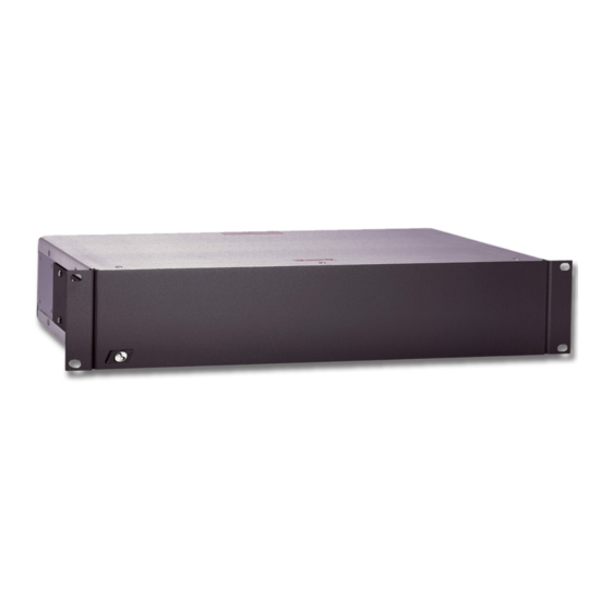
2032
Alarm Responder
Installation and Operating Instructions
This manual describes the installation and operating procedures for the American Dynamics model 2032 Alarm Responder.
The 2032 Alarm Responder can be used with all American Dynamics Matrix Switching Systems to follow and respond to
alarm conditions. The 2032 Alarm Responder provides a relay closure when a monitor goes into an alarm condition. The
relay closures may be used to start a VCR or other such device. Other uses include the operation of panel displays showing
alarmed monitors.
Advertisement

Related Manuals for American Dynamics AD2032


Summary of Contents for American Dynamics AD2032
- Page 1 This manual describes the installation and operating procedures for the American Dynamics model 2032 Alarm Responder. The 2032 Alarm Responder can be used with all American Dynamics Matrix Switching Systems to follow and respond to alarm conditions. The 2032 Alarm Responder provides a relay closure when a monitor goes into an alarm condition. The relay closures may be used to start a VCR or other such device.
- Page 2 The software/firmware furnished with this equipment is confidential to and is copyrighted by SENSORMATIC ELECTRONICS CORPORATION. It is not to be copied or disclosed in any manner without the express written consent of SENSORMATIC. The software/firmware is furnished to the purchaser under a license for use on a single system. Information furnished by SENSORMATIC is believed to be accurate and reliable.
- Page 3 The installation of this product should be made by qualified service personnel and should conform to all local codes. CAUTION RISK OF ELECTRIC SHOCK DO NOT OPEN CAUTION: TO REDUCE THE RISK OF ELECTRIC SHOCK, DO NOT REMOVE COVERS (OR BACK) . NO USER-SERVICEABLE PARTS INSIDE.
-
Page 5: Table Of Contents
Table of Contents Description ... 1 Features ... 1 Installation... 2 Setup ... 2 Monitor Select... 2 Connections Relay Connections ... 3 Data Line Connections... 3 Control Code Line Connections... 4 Operation... 5 Power Sources ... 5 Powering Up... 5 Typical System Connections ...Appendix Specifications ...back page... -
Page 7: Description
The 2032 Alarm Responder provides relay contact closures which correspond to Matrix Switching System monitors that are in an alarm condition. The Alarm Responder reads the switching system's LAN/Data Line or Control Code interface to determine which monitor is in alarm, then provides a contact closure that corresponds to the monitor in alarm. -
Page 8: Installation
For optimum performance, the 2032 Alarm Responder should be located near the Switching System Controller or near the Data Line or Control Code Line of the Matrix Switching System. -
Page 9: Connections
LAN IN/OUT). Use a good grade RG-59 video cable (Belden 8241 or equivalent). The DATA LINE OUT BNC on the Alarm Responder must be fitted with a 75-ohm BNC terminator, or if used to loop to other DATA LINE controlled equipment, it must be terminated at the end of the run. -
Page 10: Control Code Line Connections
If the 2032 Alarm Responder is used with Control Code, remove the top cover of the unit and locate the DIP switch on the printed circuit board (see Figure 4, below). Set the eighth switch position of this DIP switch to the ON position. -
Page 11: Operation
DIP switch should be in the ON position. Power Sources The 2032 Alarm Responder does not contain an On/Off Switch. The socket outlet shall be located near the equipment and shall be readily accessible. The 120V units are supplied with a pendant 3-wire cord and plug for mating to the primary source outlet. - Page 13 APPENDIX...
- Page 15 25262728 G1 IN G1 OUT G2 IN G2 OUT Relay Group 1 Output Connections or Cascading to other 2032's 2032 ALARM RESPONDER DATA LINE 13141516 29303132 G1 IN G1 OUT G2 IN G2 OUT DATA LINE/LAN OUT to Additional 2032's, Bays,...
-
Page 16: Typical System Connections
J J J J 1 1 1 1 O O O O U U U U T T T T TYPICAL SYSTEM CONNECTIONS 2032 ALARM RESPONDER with 1691 B B B B W W W W S S S S... - Page 17 ABCDEF DATA ABCDEF GROUP 2 ABCDEF B W S 2032 ALARM RESPONDER with 1650 7 8 9 10 11 12 13 14 16 17 18 A A A A A A A A A A A A 31 32 33 34 35 36...
- Page 18 DATA ABCDEF GROUP ABCDEF ABCDEF B W S TYPICAL SYSTEM CONNECTIONS 2032 ALARM RESPONDER with 1024 ALARM CONTACTS 9 10 11 12 13 14 15 16 17 18 37 38 39 40 41 42 61 62 63 64 PORTS To 1024 Bays and 2032 for MONITORS 65-128...
-
Page 19: Declaration Of Conformity
93/68/EEC, and the EMC Directive, 89/339/EEC as amended by 93/68/EEC. Pearl River, NY, USA 15 December, 2000 Harold D. Johnson, Ph.D. Director of Engineering 7, rue Alexis de Tocqueville, Parc de Haute Technologie, 92183 ANTONY CEDEX Alarm Responder AD2032-1 European Contact: Sensormatic France S.A. -
Page 20: Specifications
SPECIFICATIONS Electrical Ratings: AD2032 AD2032-1 Relay Contact Ratings: 0.6 A, 24 VAC; 2 A, 30 VDC Mounting: Surface Mount or Rack Mount Weight: 7 lbs (1.4 Kg) Finish: Shadow Gray Dimensions: 17" W x 3.5" H x 8" D (432 x 89 x 203 mm)