Advertisement
DIGITAL FM
STEREO
TRANSMITTER
Ramsey Electronics Model No.
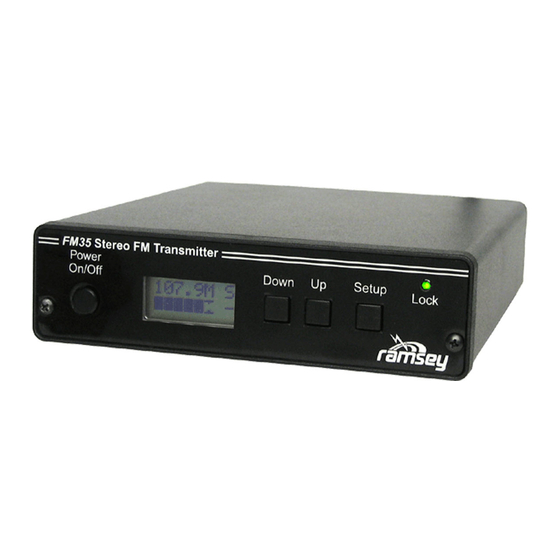
A new and improved version of our popular stereo transmitters,
the FM35 is an ideal upgrade for improved performance and
ease of use! With a low-noise design and a metal case, the
FM35 suffers from much less interference for a better S/N ratio.
The FM35 also has full digital front panel control of output
power, volume, balance, stereo/mono, and frequency!
Synthesized 87.9MHz to 108.1MHz for no frequency drift! Direct
digital input of frequency, no jumpers or DIP switches!
Designed for extruded, rugged metal case, all lines have RF
chokes, and fully regulated for the cleanest sounding low noise
performance yet!
BNC style RF output for easy, reliable connections.
Fully digitally controlled transmit power for custom coverage
capabilities!
Digital volume and balance controls for easy audio level
adjustments.
Runs from 13.8-16VDC, includes 15V DC adapter.
Quality of signal indicator lets you know when you have a good
signal or over-modulated signal. Lets you know when to turn it up,
or down!
Great for schools, health clubs, yard casting, drive-in movie
theaters, haunted rides, amusement parks, churches, etc!
FM35 1
FM35
Advertisement

Related Manuals for Ramsey Electronics FM35


Summary of Contents for Ramsey Electronics FM35
- Page 1 FM35 is an ideal upgrade for improved performance and ease of use! With a low-noise design and a metal case, the FM35 suffers from much less interference for a better S/N ratio. The FM35 also has full digital front panel control of output power, volume, balance, stereo/mono, and frequency! ...
- Page 2 COPYRIGHT 2007-2011 by Ramsey Electronics, LLC, 590 Fishers Station Drive, Victor, New York 14564. All rights reserved. No portion of this publication may be copied or duplicated without the written permission of Ramsey Electronics, LLC. Printed in the United States of America. FM35 2...
-
Page 3: Table Of Contents
TRANSMITTER TABLE OF CONTENTS Introduction .......... 4 Circuit Description ....... 5 FM35 Setup ........10 FM35 Schematic Centerfold ....12 Antenna Ideas ........14 Appendix A: FCC Rules and Info ..16 Appendix B: ........18 Summary ........... 20 Warranty ..........23... -
Page 4: Introduction
FM35 is not a toy. We will refer to the FCC regulations frequently in this manual and provide you with some information necessary to enjoy the FM35's capabilities in accordance with the law. -
Page 5: Circuit Description
We will begin by talking about the new and improved power supply section of the FM35. First off take a look at L1, C8, and C7. These parts form a low- pass filter designed to remove any RF from escaping through the power jack... - Page 6 In our case, the comparator is designed to detect peaks over +/-75kHz of deviation, which is the standard bandwidth used by radio stations. If you run the volume up too high on the FM35, the comparator reference level is surpassed often, the micro counts this, and an indicator on the display will show a poor quality of signal indication.
- Page 7 If the frequency is too low, U3’s PLL tells pin 7 to turn up the voltage. This signal on pin 7 needs to be filtered and amplified for good control, and that is FM35 7...
- Page 8 U3 on pin 11 is small, just enough to cover a room, so we need to boost it a little. U8 is a high-gain amplifier which will get up the level for us so the FM35 has a little more “oomph”. However we don’t want too much “oomph” where we don’t need it, so before the final amp we have D8, which is another special...
- Page 9 COMPARATOR, VARACTOR DIODE, PIN DIODE, LOW PASS FILTER, DIGITAL POT, DAC (Digital to Analog Converter), MULTIPLEX. Have fun and happy broadcasting! -Ramsey Staff. FM35 9...
-
Page 10: Fm35 Setup
FM35 SETUP: It’s time to set up and test your FM35, then get on the air. You’ll need an an- tenna and a line level audio source such as a CD player or computer sound card. Here we go! FM35 operation is about as simple as it gets. The [SETUP] button cycles through the various screens, and the [UP]/[DOWN] button adjusts the value on the particular screen. - Page 11 FM35 audio inputs to speaker outputs of a high power stereo system; such a connection will destroy the IC chip. Trust us when we say that a true line level audio source will give you the best results with your FM35.
-
Page 12: Fm35 Schematic Centerfold
FM35 SCHEMATIC CENTERFOLD FM35 12... - Page 13 FM35 13...
-
Page 14: Antenna Ideas
FM35. Consult the litera- ture that came with your stereo equipment. Even if you intend use of the FM35 for your own home and family, it is still your responsibility, in accordance with Part 15 of the FCC Rules, to ensure that this operation does not cause interference to your neighbors. - Page 15 Also, because such an installation is beyond the original purpose of this product and the safety standards intended for all Ramsey kits, and because we have not tested the FM35 in such an in- stallation, we cannot provide further details.
-
Page 16: Appendix A: Fcc Rules And Info
Licensed FM broadcast stations and their listeners have ALL the rights! Your use of a device such as the FM35 kit MAY have some limited privileges in lo- cally-unused band space, but your non-licensed use of the FM35 has abso- lutely NO rights at all over the rights of licensed broadcast operators and the rights of their listeners to interference-free reception. - Page 17 May, 1990. This is only a brief look at the rules and should not be con- strued to be the absolute complete legal interpretation! It is up to you to oper- ate within the proper FCC rules and Ramsey Electronics, Inc. cannot be held responsible for any violation thereof.
- Page 18 FM stations, this is a "generous" limitation de- signed to accommodate cruder FM devices. Properly built and adjusted, the FM35 kit operates well within this limit. In fact, its signal should sound no "wider" than any other FM station when listening on an ordinary FM radio.
- Page 19 For other kinds of radio services, the FCC restricts such factors as transmitter power or antenna height, which cannot really limit the possible "range" of a transmission under good conditions. By restricting the maximum field strength FM35 19...
-
Page 20: Summary
The present edition of Part 15 of the FCC rules does not provide detailed guidance on ALL aspects of using a low-power transmitter such as the FM35. The main point is that you may not cause any interference whatsoever to li- censed broadcast services and that you must be willing to put up with any in- terference that you may experience. - Page 21 If you become further fascinated with the service rendered by low-power broadcasting, other FCC regulations explain how to apply for a license or other authorization which may permit you to upgrade your FM35 or other equipment to accomplish any objective which the FCC sees to be in the public interest and not interfering with other authorized uses of the radio spectrum.
- Page 22 As our customers, we value your opinions, com- ments, and additions that you would like to see in future publications. Please submit comments or ideas to: techsupport@ramseyelectronics.com And once again, thanks from the folks at Ramsey! FM35 22...
-
Page 23: Warranty
“1K ohm” resistors are actually the “missing” 10 K parts ("Hum-m-m, I guess the orange band really does look red!") Ramsey Electronics project kits are packed with pride in the USA by our own staff personnel. - Page 24 RAMSEY ELECTRONICS, LLC 590 Fishers Station Drive Manual Price Only: $5.00 Victor, New York 14564 Ramsey Publication No. FM35 Phone (585) 924-4560 Assembly and Instruction manual for: (585) 924-4555 RAMSEY MODEL NO. FM35 DIGITAL www.ramseykits.com FM35 24 FM STEREO TRANSMITTER...