Table of Contents
Advertisement
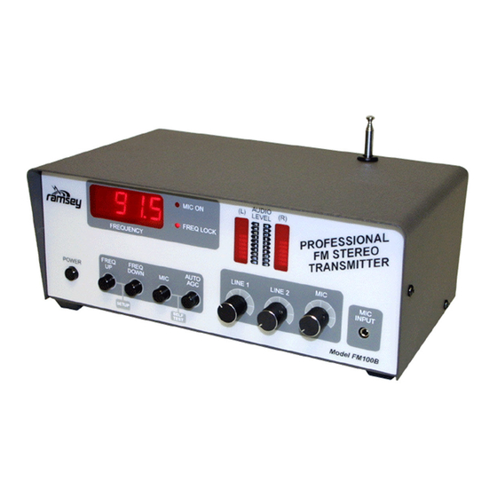
Ramsey Electronics Model No.
Here's the ultimate radio transmitter for all of you home brew
DJs out there! This all-in-one stereo transmitter has all the
features you will ever need for transmitting a school radio
station, around your yard, or even around the block.
Use the optional high power configuration for extra boost
when transmitting outside of the US!
•
2 Line inputs and one mic input-plus a built in mixer!
•
New Line output for monitoring your show!
•
PLL Crystal controlled for rock solid frequency
•
Left and right channel peak hold indicators and large LED frequency
display
•
Built in power supply, just plug it in! Now operates from 85-264VAC (47 - 63
Hz) without jumpers!
•
25 mW output standard, optional 1W configuration for operation outside
the US!
•
Auto AGC microphone muting function for cool talk-overs
•
Rugged steel enclosure for years of service
FREQ
POWER
FREQUENCY
FREQ
UP
DOWN
MIC
SETUP
(L)
MIC ON
FREQ LOCK
LINE 1
AUTO
AGC
SELF
TEST
FM100B • 1
FM100B
AUDIO
LEVEL
(R)
+9
+9
+6
+6
+3
+3
0
0
-3
-3
-6
-6
-9
-9
-12
-12
-15
-15
-18
-18
MIC
LINE 2
MIC
INPUT
Model FM100B
Advertisement
Chapters
Table of Contents

Related Manuals for Ramsey Electronics FM100B


Summary of Contents for Ramsey Electronics FM100B
- Page 1 Ramsey Electronics Model No. FM100B Here’s the ultimate radio transmitter for all of you home brew DJs out there! This all-in-one stereo transmitter has all the features you will ever need for transmitting a school radio station, around your yard, or even around the block.
- Page 2 Ramsey Electronics publication No. MFM100B Revision 1.4b First printing: January 2002 COPYRIGHT 2002 by Ramsey Electronics, Inc. 590 Fishers Station Drive, Victor, New York 14564. All rights reserved. No portion of this publication may be copied or duplicated without the written permission of Ramsey Electronics, Inc.
-
Page 3: Table Of Contents
Main Board Layout ......35 Rear Panel Wiring Pictures ....43 Testing and Calibration ....49 Troubleshooting ....... 51 Warranty........... 55 RAMSEY ELECTRONICS, INC. 590 Fishers Station Drive Victor, New York 14564 Phone (585) 924-4560 Fax (585) 924-4555 www.ramseykits.com FM100B • 3... -
Page 4: Introduction
Electronics in order to give you an idea of how we arrived at the development of the FM100B as our latest stereo transmitter. We have many people call us each day asking questions about our earlier versions of transmitters such as the FM25B and the FM10A. -
Page 5: Circuit Operation
Here is where we get into a little circuit analysis. If you just want to plug it in and start broadcasting you can skip this section and read the FCC regulations at the end. Otherwise read on to learn how the FM100B works. We will reference the schematic often as we analyze the circuit. - Page 6 So how does this PLL and VCO (Voltage Controlled Oscillator) work in our FM100B? While there are not a lot of parts surrounding U2, there is a lot going on inside behind the scenes. In order for you to understand what goes on behind the scenes, a little PLL theory wouldn’t hurt.
- Page 7 U2. We are going to take a closer look at the microphone amplifier, audio mixer, audio switcher, and peak hold meters to find out the purpose of each. For ease of description we will only FM100B • 7...
- Page 8 U1 enables or disables the Auto AGC feature of the FM100B. The Auto ACG feature works by U12 detecting a level of audio from the microphone, and if loud enough, U13, set up as a level detector, mutes the audio coming in by turning on Q7 and Q8.
- Page 9 Now we can go back to the microphone amplifier. U12 is a microphone conditioner IC. It has a feature that we use in the FM100B that really help us out by eliminating a lot of manual work. This is the AGC or Automatic Gain Control.
- Page 10 This completes the basic analog circuit description of the FM100B. If you are interested in more detail of how it works, there are many good books and magazines which deal with circuitry of this sort in smaller manageable circuits which can help you delve further in what is going on.
- Page 11 The part is then soldered securely to the board (2-4), and the remaining lead length is then clipped off (5). Notice how the solder joint looks on close up, clean and smooth with no holes or sharp points (6). FM100B • 11...
-
Page 12: Parts List
Let’s begin by sorting out our components and cross-checking them against the parts list to make sure we have received everything. IMPORTANT NOTE! The surface mount parts in your FM100B have been preinstalled for you. Please do not call the factory for your missing parts;... - Page 13 FM100B PARTS LIST Semiconductors 2 MV2105 Varactor Diodes (In TO-92 case, 2 pins) (D1,2) 4 2N3904 NPN General purpose transistors (Q1,3,4,5) 3 BS170 JFET Transistors (Q2,7,8) 5 1N4148 Switching Diodes (orange glass body, black stripe) (D3,4,5,6,9) 1 7805 +5V Voltage Regulator (VR1)
- Page 14 1 2.2 uH inductor (like a fat resistor with red-red-gold-silver bands) (L7) 1 13 turn air core inductor (L8) Display Indicators 2 MAN6910 Dual high efficiency seven segment displays (DISP1,2) 2 10-segment bargraph displays (DISP3,4) 2 Small red LEDs (D7,8) FM100B • 14...
- Page 15 1 Roll of fine 60/40 solder (less than .045” diameter) 1 Sensitive voltmeter or DMM 1 An FM radio for testing 1 Audio sources such as a tape deck, CD player, or microphone 1 Egg carton or grapefruit holder to sort out parts in. FM100B • 15...
- Page 16 Audio Mixer ........24 Low Pass Audio Filters.....26 Peak Hold Meters.......30 Transmitter.........32 G Transmitter Amplifier ......36 Microcontroller ........38 Power Supply........40 Jacks and Switches ......42 Rear panel wiring.......45 PCB Mounting........48 M Final Testing and Calibration ...49 Final Case-up ........51 FM100B • 16...
-
Page 17: Section Layout
SECTION LAYOUT ON MAIN BOARD FM100B • 17... - Page 18 DISPLAY BOARD PARTS LAYOUT DIAGRAM Parts Layout Note: Light Gray components are mounted on the reverse side of the board. FM100B • 18...
-
Page 19: Display Board
1 is. This will be installed in the same orientation as the notch in the parts layout diagram. Solder all 20 pins. FM100B • 19... - Page 20 16A. Install J10, another five pin jumper block. This is where the power for the bargraphs is applied and the signal levels for the bargraphs are sent for display (mount it on the backside like J11). FM100B • 20...
- Page 21 Great job! We have just completed the display board and we are almost ready to move on. First we want to check our display board to make sure there are no solder bridges or cold solder joints. Next, check the orientation of your parts for correct installation. FM100B • 21...
-
Page 22: Microphone Amp
It looks like the silkscreen for R34 says R3 but it is the correct position, the 4 was simply cut off. FM100B • 22... - Page 23 In the mean time this completes the microphone section. Before we continue we should check over the part orientation for your diodes, capacitors, the IC, and the transistors. If we check in small sections it will be easier to find mistakes. FM100B • 23...
-
Page 24: Audio Mixer
10C. Install R52, a 10K ohm resistor (brown-black-orange). 11C. Install R43, a 22K ohm resistor (red-red-orange). 12C. Install R62, a 1K ohm resistor (brown-black-red). 13C. Install R78, a 10K ohm resistor (brown-black-orange). Note this resis- tor is mounted in a stand-up fashion. FM100B • 24... - Page 25 You would be surprised how many problems you can find when you do this. Onward! FM100B • 25...
-
Page 26: Low Pass Audio Filters
10D. Install R83, a 10.0K ohm 1% resistor (brown-black-black-red-brown). 11D. Install R87, a 39K ohm 5% resistor (orange-white-orange-gold). 12D. Install R94, a 10K ohm 5% resistor (brown-black-orange-gold). 13D. Install R75, a 121K ohm 1% resistor (brown-red-brown-orange-brown). 14D. Install R92, a 51.1K ohm 1% resistor (green-brown-brown-red-brown). FM100B • 26... -
Page 27: Display Schematic
DISPLAY SCHEMATIC FM100B • 27... - Page 28 34D. Install R66, a 3.32K ohm 1% resistor (orange-orange-red-brown- brown). 35D. Install R56, a 10.0K ohm 1% resistor (brown-black-black-red-brown). 36D. Install R61, a 39K ohm 5% resistor (orange-white-orange-gold). 37D. Install R67, a 10K ohm 5% resistor (brown-black-orange-gold). FM100B • 28...
- Page 29 Again check for solder bridges and cold solder joints. Especially check around the pins of the ICs for solder bridges since it is a common occurrence. FM100B • 29...
-
Page 30: E Peak Hold Meters
5E. Install U7, a LM358 opamp. Make sure to orient it in the same direction as shown in the Parts Layout Diagram. Check all 8 pins to be sure they are through the board before soldering any of them! 6E. Install C81, a 10 uF electrolytic capacitor. Check polarity! FM100B • 30... - Page 31 (preferably caffeinated) and give yourself another eyeball break! Our next section is the toughest of the whole kit so make sure you have all of your skills primed and ready for the true test! FM100B • 31...
-
Page 32: Transmitter
9F. Install C38, a 150 pF ceramic capacitor (marked 151). 10F. Install C37, a 0.0033 uF ceramic capacitor (marked 332). 11F. Install C33, a 150 pF ceramic capacitor (marked 151). 12F. Install C32, another 0.0033 uF ceramic capacitor (marked 332). FM100B • 32... - Page 33 TO-92 type cases, but they only have two leads. This makes it easy to orient them properly to the flat side as shown in the board layout. D1 is the primary tuning diode. FM100B • 33...
- Page 34 Be careful with your assembly, you wouldn’t want to get this far and then make a mistake causing the project not to work. With soldering iron in hand, on to the next section! FM100B • 34...
-
Page 35: Main Board Layout
MAIN BOARD PARTS LAYOUT FM100B • 35... -
Page 36: G Transmitter Amplifier
@ =Not Placed G. TRANSMITTER AMPLIFIER This section covers the transmitter section of the standard FM100B. If you pur- chased the High Power version, you will be installing the added components right after these steps before you move on to the Microcontroller section. U6 has already been installed for you. - Page 37 25G. Remove the whip antenna until the later casing instructions (be care- ful, it’s hot!). Jump to the High Power Manual (FM100BEX) if you have purchased that ver- sion. Install the High power parts before moving on to Section H. FM100B • 37...
-
Page 38: Microcontroller
8H. Install R4, a 10K ohm resistor (brown-black-orange). 9H. Install C10, a 0.1 uF ceramic capacitor (marked 104). 10H. Install R12, a 10 ohm resistor (brown-black-black). 11H. Install SP1, the mini speaker. Make sure the + terminal (labeled on FM100B • 38... - Page 39 Parts Layout Diagram to prevent confusion later. 17H. Install U1, the IC with the sticker labeled FM100B into the socket. Find the dot or notch on one end of the chip and orient it as shown in the Parts Layout Diagram.
-
Page 40: I Power Supply
10I. Install J5, the 3.5 mm microphone jack. Solder all 5 pins. 11I. Install J1, the three pin Molex connector. Make sure and mount the short ends in the PC board and orient the jack so that the locking header mounts toward the center of the board. FM100B • 40... - Page 41 To assist you in checking your project out, have an associate check your work for you. You may be surprised what they can point out for you! FM100B • 41...
- Page 42 The traces on the back of the power supply module are also potentially lethal! Make sure any of the parts located on the main board of the FM100B (especially under the power supply module) are soldered close to the board. The destruction will be catastrophic should...
- Page 43 #4-40x1/4" Screw wires are used) to go between J1 and the AC IN jack of the power supply. Orientation is not as critical here but use the locking headers as a guide. PS1 POWER SUPPLY WIRING CLOSE-UP FM100B • 43...
-
Page 44: Rear Panel Wiring Pictures
REAR PANEL WIRING PICTURES AC Input and RF Output Fuse Wiring Close-up FM100B • 44... -
Page 45: Rear Panel Wiring
(as shown above) into the header jack. Notice there is a small catch tab on one side of the pin. Insert the pin into the Molex jack so the tab faces the side with the slotted holes (you’ll hear a small “click” if properly installed). FM100B • 45... - Page 46 Hold down wires the board between (solder 3 wire loops over the silkscreen writing coax to hold it in place) for J7 and L8. It needs to be grounded to the PC board at this position. FM100B • 46...
- Page 47 When you have completely finished the unit and it’s up and running, you may want to coat these connections with nonconductive 100% silicone (such as tub sealant). Be careful to not get it inside the switch movement however or you won’t have a good switch any longer! FM100B • 47...
-
Page 48: Lpcb Mounting
7L. Using 3 of the #4-40x1/4” screws, mount the board securely to the front panel. 8L. Admire your work up to this point. (WOW!) Now we are getting somewhere! Is it ever tempting to plug it in. But wait, flip the page first! FM100B • 48... -
Page 49: Testing And Calibration
A receiver (preferably digital tuner). The tuning tool sent with your kit. 1M. Make sure the power switch is off. Plug in your FM100B to line power. 2M. Turn on the FM100B. All of the used digits of the display should light (like this 1.8.8.8.), the speaker will beep, and then go to some frequency. - Page 50 26M. Use the provided tuning tool to adjust your RF output power control (R36) as needed for your intended coverage area; turn clockwise for maximum power. Set this only as high as needed. 27M. Consult the troubleshooting section should you have any problems. FM100B • 50...
-
Page 51: Troubleshooting
9.9V then the VCO may not be oscillating. Make sure the crystal is 7.60 MHz. Check around L1, Q3, Q4, U2, D2, and D1. PROBLEM: One channel is out completely, other one sounds OK. SOLUTION: More than likely there is a short somewhere in any one of the FM100B • 51... - Page 52 SOLUTION: Give us a call at (585) 924-4560. While some problems can be answered on the phone, others cannot. Read the warranty information in the manual for information on how to send your unit in. Upon its return it will be fully functional according to our specifications. FM100B • 52...
-
Page 53: Warranty
But on rare occasions a sour component can slip through. All our kit parts carry the Ramsey Electronics Warranty that they are free from defects for a full ninety (90) days from the date of purchase. Defective parts will be replaced promptly at our expense. If you suspect any part to be defective, please mail it to our factory for testing and replacement. - Page 54 FM100B • 54...
- Page 55 FM100B • 55...
- Page 56 • Desoldering Braid Ramsey RTS08 Price: $10.00 TOTAL SOLDER POINTS Ramsey Publication No. MFM100B Assembly and Instruction manual for: RAMSEY MODEL NO. FM100B ESTIMATED ASSEMBLY TIME Beginner ....24 hrs Intermediate ..18 hrs Advanced..... 10 hrs RAMSEY ELECTRONICS, INC.