Table of Contents
Advertisement
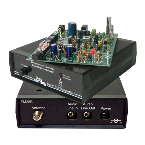
SYNTHESIZED FM
STEREO TRANSMITTER
Ramsey Electronics Model No.
Own and operate your own FM Stereo broadcast station. The
FM25B has an exceptional synthesized transmission range and
improved audio quality that puts your favorite radio station to
shame.
•
Synthesized 88 to 108 MHz for no frequency drift!
•
No annoying Hum with even better stereo separation than the
original!
•
New design features 'Line In' and 'Loop Out' 1/8" Stereo jacks!
•
'F' style RF output connector for easy connection to an external
antenna
•
Fully adjustable RF output level for custom coverage capabilities!
•
Kit includes case, AC adapter, 1/8" Stereo to RCA patch cable, and
whip antenna
•
Great for schools, health clubs, realtors... or your back yard!
•
The ideal campus or school radio station
•
Clear, concise instructions guide you step-by-step to a finished
product that works FIRST time.
FM25B • 1
FM25B
Advertisement
Table of Contents

Related Manuals for Ramsey Electronics FM25B


Summary of Contents for Ramsey Electronics FM25B
- Page 1 STEREO TRANSMITTER Ramsey Electronics Model No. FM25B Own and operate your own FM Stereo broadcast station. The FM25B has an exceptional synthesized transmission range and improved audio quality that puts your favorite radio station to shame. • Synthesized 88 to 108 MHz for no frequency drift! •...
- Page 2 Ramsey Electronics publication No. FM25B Rev 1.2a First printing: November 2001 COPYRIGHT 2001 by Ramsey Electronics, Inc. 590 Fishers Station Drive, Victor, New York 14564. All rights reserved. No portion of this publication may be copied or duplicated without the written permission of Ramsey Electronics, Inc.
-
Page 3: Table Of Contents
STEREO TRANSMITTER TABLE OF CONTENTS Introduction ........4 Circuit Description ......5 Parts Layout Diagram ...... 9 FM25B Parts List ......10 FM25B Assembly ......12 Custom Case Assembly ....20 Choosing an Operating Frequency .. 20 Adjusting .......... 21 Home Use ........ -
Page 4: Introduction
FM25B is not a toy. We will refer to the FCC regulations fre- quently in this manual and provide you with some information necessary to en- joy the FM25B's capabilities in accordance with the law. -
Page 5: Circuit Description
12 Volt regulator! Now that we have a clean power source, let’s dive into the rest of the kit! The custom FM stereo IC (U3) is the heart of the FM25B. U3 is a microproces- sor controlled FM stereo generator with lots of built-in performance features. - Page 6 Our application for this circuit gives the user feedback about the operating status of the unit. The combined stages used with their support components act as a dual purpose pulse detector. The opamp (U1) cir- FM25B • 6...
- Page 7 (stereo / mono) selection. You may think that all this would take a long time but in fact the whole process of sending the data takes less than 1/100th of a second! U3’s internal phase locked loop (PLL) synthesizer requires a 7.6 MHz refer- FM25B • 7...
- Page 8 (LC) ]), bring- ing the FM25B’s output frequency back on frequency to match that of the ref- erence. If the desired frequency is higher than the reference, U1 does just the reverse and sends a series of controlled pulses close to the chip’s 5 Volt rail from a 1/2 VCC midpoint on pin 7.
-
Page 9: Parts Layout Diagram
FM25B PARTS LAYOUT DIAGRAM FM25B • 9... - Page 10 PARTS SUPPLIED WITH FM25B: Note the extra chip capacitors included. Capacitors .001 µF disc capacitors (marked .001, 102 or 1nF) [C13,14,18,31,33,35,36] .01 µF disc capacitors (marked .01 or 103 or 10 nF) [C2,5,26] .1 µF disc capacitors (marked .1 or 104 or 100 nF) [C7,21,23] .047 uF ceramic capacitor (marked .047 or 473) [C6]...
- Page 11 2.1mm DC power jack [J2] DPDT push-button switch [S4] DIP switches (8 pin dip with 4 sliding tabs) [S1,2,3] Whip antenna [ANT1] FM25B printed circuit board 1/8” stereo to RCA cable AC125 12 volt DC power transformer Required, not supplied...
-
Page 12: Fm25B Assembly
PC board over and you’ll find them soldered into place. Since you may appreciate some "warm-up" soldering practice as well as a chance to put some "landmarks" on the FM25B PC board, we'll first install some "hardware" components, to make the up-down, left-right orientation of the PC board as clear as possible. - Page 13 Be sure to solder all 14 pins. 3. Now insert U2 into the socket. Orient the notched end as shown on the PC board silkscreen, toward R12. Before you push it down into the FM25B • 13...
- Page 14 14. Install the other 10k trimmer pot, R27 (marked 103). 15. Install J5, one of the stereo jacks. Proper positioning of this part will help you later with case-up so be sure it’s where you want it before solder- ing. FM25B • 14...
- Page 15 29. Install C24 and C27, 3300 pF (marked 332 or 0.0033). For use in Europe, use 2200 pF capacitors (marked 222 or .0022). These capacitors set the pre-emphasis characteristics for the FM25B. Pre-emphasis is a technique used in FM transmitters to increase the high frequency signal to noise ratio.
- Page 16 Bad things can hap- pen when electrolytics are installed backwards! 55. Install R18, 22k ohms (red-red-orange). 56. Install R17, 100 ohms (brown-black-brown). 57. Install R14, 10k ohms (brown-black-orange). FM25B • 16...
- Page 17 FM25B. Also, if you decide to cut a hole in the side of the enclosure so that you can reach the DIP switches without taking the cover off, you’ll be glad they’re placed that way!
- Page 18 That way you won’t have to search for it if you ever want to operate in mono. 87. Install R11, 10k ohms (brown-black-orange). 88. Install C3, 100 µF electrolytic capacitor. Watch your orientation. FM25B • 18...
-
Page 19: Choosing An Operating Frequency
94. Install Q1, the last 2N3904 transistor. Again, be sure it is placed cor- rectly before soldering. That’s it! But before you grab the power supply and fire up the FM25B, take a moment to check over your work. Check to be sure that all the parts are in- stalled and the polarity sensitive ones are placed properly. -
Page 20: Adjusting
Part 15 of FCC regulations, it is your responsibility to determine carefully that your operation will not cause interference to broadcast reception. Please study Appendix A of this manual before using your FM25B. ADJUSTING YOUR FM25B TRANSMITTER Keep all tests very brief until you have carefully chosen an open operating fre- quency in the FM broadcast band. - Page 21 The most important setting is at 107.9 MHz. Remember that if you have adjusted the FM25B outside of 88 MHz to 108 MHz range it will default to 88.1 MHz. This means that if you can’t hear any- thing on the radio near the frequency you are trying to transmit at, go to 88.1...
-
Page 22: Projects
FM25B. Consult the lit- erature that came with your stereo equipment. Even if you intend use of the FM25B for your own home and family, it is still your responsibility, in accordance with Part 15 of the FCC Rules, to ensure that this operation does not cause interference to your neighbors. - Page 23 If your situation involves a single large building or multi-level home where re- ception from the FM25B antenna may tend to be uneven because of walls and other VHF path obstacles, you might set up the FM25B's output in a "carrier- current"...
-
Page 24: Troubleshooting
Also, because such an installation is beyond the original purpose of this kit and the safety standards intended for all Ramsey kits, and because we have not tested the FM25B in such an instal- lation, we cannot provide further details. -
Page 25: Fcc Rules And Information
In the United States, this is how the FCC regards your transmitter kit Licensed FM broadcast stations and their listeners have ALL the rights! Your use of a device such as the FM25B kit MAY have some limited privileges in locally-unused band space, but your non-licensed use of the FM25B has ab- solutely NO rights at all over the rights of licensed broadcast operators and the rights of their listeners to interference-free reception. - Page 26 May, 1990. This is only a brief look at the rules and should not be con- strued to be the absolute complete legal interpretation! It is up to you to oper- ate within the proper FCC rules and Ramsey Electronics, Inc. cannot be held responsible for any violation thereof.
- Page 27 1830 ACRES signed to accommodate cruder FM devices. Properly built and adjusted, the FM25B kit operates well within this limit. In fact, its signal should sound no "wider" than any other FM station when listening on an ordinary FM radio.
- Page 28 "range" of a transmission under good conditions. By restricting the maximum field strength at a specific distance from your antenna, the FCC clearly plans for your signal FM25B • 28...
- Page 29 A "sensitive" receiver responds to a signal of 1 or even .5 microvolts "delivered" to the receiver input by antenna. If the an- tenna is not good, the receiver cannot respond to the presence of fractions of a microvolt of RF energy. FM25B • 29...
-
Page 30: Summary
ALL aspects of using a low-power transmitter such as the FM25B. The main point is that you may not cause any interference whatso- ever to licensed broadcast services and that you must be willing to put up with any interference that you may experience. - Page 31 CB (now 3 bands of it, for varying applications) to easy entry-level Amateur Radio with long-term licensing, to numerous unlicensed Part 15 operations, the FCC is beginning to look out for the interest and good plans and intentions FM25B • 31...
- Page 32 Learn the rules...observe them...and have fun in radio! If you enjoyed this Ramsey kit, there’re plenty more to choose from in our catalog - write or call today! FM25B • 32...
- Page 33 FM25B • 33...
- Page 34 FM25B • 34...
-
Page 35: Warranty
But on rare occasions a sour component can slip through. All our kit parts carry the Ramsey Electronics Warranty that they are free from defects for a full ninety (90) days from the date of purchase. Defective parts will be replaced promptly at our expense. If you suspect any part to be defective, please mail it to our factory for testing and replacement. -
Page 36: Victor, New York
SYNTHESIZED STEREO TRANSMITTER KIT Quick Reference Page Guide Introduction ........4 Circuit Description ......5 Parts Layout Diagram ...... 9 FM25B Parts List ......10 FM25B Assembly ......12 Troubleshooting ....... 25 FCC Rules and Information ..... 26 Understanding Field Strength ..29 Summary .........