Alesis ADAT-M20 Owner's Manual
20-bit digital recorder
Hide thumbs
Also See for ADAT-M20:
- Command list (11 pages) ,
- Supplementary manual (17 pages) ,
- Owner's manual (9 pages)

Related Manuals for Alesis ADAT-M20


Summary of Contents for Alesis ADAT-M20
- Page 1 ROFESSIONAL IRST PPLIES TO NCLUDES SOFTWARE LESIS ECORDER ’ WNER ANUAL DITION ERSION PERATING OFTWARE ERSION 1999 A LESIS ORPORATION IGITAL 1.06 1.11 ERSION 2.10 A DDENDUM...
- Page 2 M20 R 1.06 LESIS EFERENCE ANUAL...
-
Page 3: Table Of Contents
Important Safety Instructions and Compliance Notices ...vii Safety symbols used in this product ... vii Please follow these precautions when using this product: ... vii Instructions de Sécurité Importantes ...ix Symboles utilisés dans ce produit ...ix Beim Benutzen dieses Produktes beachten Sie bitte die folgenden Sicherheitshinweise: ...x Information to the User for Class A Digital Device (FCC Part 15, Class A)...xi CE Declaration of Conformity...xii Overview, Setup, and Basics... - Page 4 Table of Contents 3.3 Editing Conventions...4 Tape Formatting...1 4.1 Sample Rate Selection...2 4.1a Pull-up and Pull-down Sample Rate Selection ...3 4.2 Word Length Selection ...3 4.3 Format a New Tape ...4 4.4 Record Tracks While Formatting...4 4.5 Extend a Partially-Formatted Tape ...5 4.6 End Formatting ...5 4.7 Certify Tape Format ...5 4.8 Reformatting: Caution!...5...
- Page 5 8.8a Setting Auto Record Punch Points...8 8.8b Enable Auto Record...9 8.8c Set Auto Punch Points “On the Fly” ...9 Autolocation ... 1 9.1 Entering, Selecting, and Editing Location Points ...1 9.1A Set Locate...1 9.1B Copy Tape Location...1 9.2 Deferred Play and Record...3 9.3 Play-After-Locate (Auto Play) ...3 9.4 Loop Between Start and End Locate Points (Auto Return)...3 9.4a Setting Loop Start and End Points...4...
- Page 6 Table of Contents 13.8 Rewind/Fast Forward TC Output (Page 8)...3 13.9 Unthread Timeout (Page 9)...3 13.10 Search Enable (Page 10)...4 13.11 Locate Before Play (Page 11) ...4 13.12 Mute Until Lock (Page 12)...4 13.13 Dynamic Punch (Page 13)...4 13.14 Track Groups (Page 14) ...4 13.15 Save Data to Tape? (Page 15) ...4 13.16 Load Data from Tape? (Page 16) ...5 13.17 Tape Type (Page 17)...5...
- Page 7 16.3a SMPTE Chase Offset ...5 16.3b Internal Generator ABS Offset ...6 16.3c Tape Offset...6 16.4 SMPTE Time Code Rates and Types...7 16.4a Drop Frame...7 16.4b Auto-detection of SMPTE Rates ...7 16.4c VITC (Vertical Interval Time Code)...8 16.4d MTC (MIDI Time Code)...8 Time Code Tutorial ...
- Page 8 Table of Contents MIDI Thru ...6 New Utility page order ...6 CADI display changes...6 Cassette Auto-Inject ...6 Deck Standby Mode ...7 Auto-Park After Formatting ...7 Deferred Eject ...7 New RS-422 Device ID ...7 Improved SMPTE Clock Source Recognition...7 Sample Rate Change During Play/Record...7 M20 R LESIS EFERENCE...
-
Page 9: Important Safety Instructions And Compliance Notices
NSTRUCTIONS AND AFETY SYMBOLS USED IN THIS PRODUCT This symbol alerts the user that there are important operating and maintenance instructions in the literature accompanying this unit. This symbol warns the user of uninsulated voltage within the unit that can cause dangerous electric shocks. LEASE FOLLOW THESE PRECAUTIONS WHEN USING THIS PRODUCT . - Page 10 When a cart is used, use caution when moving the cart/apparatus combination to avoid injury from tip-over. Alesis recommends the use of standard 19” racks designed for use with professional audio or music equipment, and the use of rear rack rail supports or sliders. In any installation, make sure that injury or damage will not result from cables pulling on the apparatus and its mounting.
-
Page 11: Instructions De Sécurité Importantes
NSTRUCTIONS DE YMBOLES UTILISÉS DANS CE PRODUIT Ce symbole alèrte l’utilisateur qu’il existe des instructions de fonctionnement et de maintenance dans la documentation jointe avec ce produit. Ce symbole avertit l’utilisateur de la prèsence d’une tension non isolèe à l’intèrieur de l’appareil pouvant engendrer des chocs èlectriques. -
Page 12: Beim Benutzen Dieses Produktes Beachten Sie Bitte Die Folgenden Sicherheitshinweise
Safety Notices 16. Ce produit, utilisè avec un amplificateur et un casque ou des enceintes, est capable de produite des niveaux sonores pouvant engendrer une perte permanente de l’ouïe. Ne l’utilisez pas pendant longtemps à un niveau sonore èlevè ou à un niveau non confortable. - Page 13 NFORMATION TO THE (FCC P EVICE This equipment has been tested and found to comply with the limits for a class A digital device pursuant to Part 15 of the FCC Rules. These limits are designed to provide reasonable protection against harmful interference when the equipment is operated in a commercial environment.
-
Page 14: Ce Declaration Of Conformity
Standards: Application of Council Directive: Safety: EMC: European Contact: April, 1998 ONFORMITY Alesis Corporation 1633 26th Street Santa Monica, CA 90404 Modular Digital Multitrack Recorder 89/336/EEC; 73/23/EEC EN 60 065 (1993) First Edition, Amendment No.1 (1994) -
Page 15: Overview, Setup, And Basics
VERVIEW The Alesis M20 is an 8-track digital tape recorder that records on S-VHS videotape cassettes. It is compatible with the ADAT format used with several other digital recorders (Alesis ADAT, ADAT XT, LX20, and XT20; Studer V-Eight; Fostex RD-8 and CX-8; and Panasonic MDA-1). -
Page 16: Unpacking And Inspection
Your M20 includes the correct power cord for your country or local area. When using an M20 abroad , use only the following alternative power cords approved for use with ADAT: For 90-120 VAC 50/60 Hz operation in the US, Canada and/or Japan, use Alesis UL/CSA power cord #7-41-0001. -
Page 17: Line Conditioners And Protectors
Alesis cannot be responsible for problems caused by using the M20 or any associated equipment with improper AC wiring. 1.4 L ONDITIONERS AND Although the M20 tolerates typical voltage variations, the AC line voltage may contain spikes or transients that can possibly stress your gear and, over time, cause a failure. There... -
Page 18: Use The Right Tape
Use only premium quality, name brand S-VHS cassettes such as Quantegy 489 DM Digital Mastering Audio Tape, or Alesis ADAT Mastering Audio Cassettes. Other acceptable brands include Maxell XR-S Black, JVC XZ, Sony DASV, BASF Digital Master 938, Apogee AA-40, HHB ADAT45, and TDK SP Super Pro. -
Page 19: Operating Environment
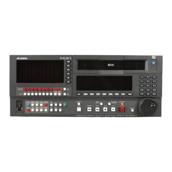
10° C to +40° C (50° F to 104° F), in up to 80% non-condensing humidity. These are not absolute limits, but Alesis cannot guarantee that the M20 will meet its published specs or remain reliable if operated outside of these ranges. - Page 20 Overview, Setup and Basics, Chapter 1 Figure 1 (M20 Front Panel) M20 R 1.06 LESIS EFERENCE ANUAL...
-
Page 21: Control And Connector Basics
ONTROL AND 2.1 A BOUT THE Referring to Fig. 1, the front panel includes: S-VHS cassette door and Eject button Main vacuum fluorescent display (toward the center) with two sets of 10-character 7- segment readouts. The left readout shows the current tape location. The right readout shows information such as incoming SMPTE time, locate address, current offset, etc. - Page 22 Control and Connector Basics, Chapter 2 Figure 2 (M20 Rear Panel with optional EC-1 AES/EBU Card) M20 R 1.06 LESIS EFERENCE ANUAL...
-
Page 23: About The Rear Panel
The optical input and output are an industry-standard digital audio interface, pioneered by Alesis, that carries 8 digital audio channels (with up to 24 bits of resolution) on a single fiber optic cable. The standard cable is a 1mm diameter plastic fiber with Toslink connectors. One 1-meter cable is provided with the M20;... -
Page 24: Video In And Thru
9-pin protocol. This feature will not be operational until M20 Version 2.0 software becomes available. ETER RIDGE This RJ-45 connector connects to an optional remote controller like the Alesis CADI remote, and/or RMD meter bridge. OWER The IEC-standard, grounded AC input plug accepts AC voltages from 90 to 250 volts, eliminating the need for transformers or voltage switches. -
Page 25: Editing M20 Operating Parameters
DITING 3.1 T EYPAD The keypad block contains switches for editing the various parameters that control the M20’s features. THROUGH Use the 10 numeric keys to enter number parameter values and letters for names. When editing a parameter value, pressing a key enters its associated number. When editing a name, pressing a key cycles through the letters indicated on the keycap (e.g., pressing 7 repeatedly cycles through 7, s, t, u, v, 7, s, t…etc.). -
Page 26: Enter/Name
Editing M20 Parameters, Chapter 3 NTER This key has two main uses: Speed up numeric entry by eliminating the need for “leading zeroes.” For example, the varispeed setting is a 3-digit value. Instead of having to key in something like 0 - 0 - 9, you can simply key in 9, then press Enter. -
Page 27: Selecting
ELECTING Most buttons have at least one associated display page, which contains one or more parameters. If there are multiple pages, the main display’s left side shows the current page number; repeatedly pressing the associated button cycles through the pages. Shortcut: To access a particular page directly, hold the associated button and use the keypad to enter the desired single-digit page number. -
Page 28: The Edit Button
Editing M20 Parameters, Chapter 3 3.2 T UTTON The Edit button toggles the M20 in and out of Edit Mode. Enabling Edit mode (button lit) allows editing parameter values for the functions grouped with the Edit button: Track Delay, Tape Offset, SMPTE Chase, Internal Gen, Format, Pre-Roll, Post-Roll, Auto Return, and Auto Record. -
Page 29: Tape Formatting
Formatting is essential to the ADAT system. It creates a sample-accurate time reference (i.e., it’s accurate to 1/48,000th of a second when recording at 48 kHz) on each tape, in addition to block ID codes, linear control track, and other essential markers. This provides tight synchronization ó... -
Page 30: Sample Rate Selection
Formatting Tape, Chapter 4 4.1 S AMPLE Choose between 44.1 kHz (CD/consumer standard) or 48 kHz (DAT/professional standard). Here are some general hints: If mixing the tape through a digital mixer for a CD master, use 44.1 kHz to avoid sample rate conversion. -
Page 31: Word Length Selection
UP AND The Sample Rate button is also used to select the respective 0.1% pull-up and pull-down rates. A pull-up is available with a 30 fps SMPTE rate only. A pull-down is available with a 29.97 fps SMPTE rate only. Use pull-up or pull-down after a standard tape format: It is not necessary to pre-select a pull-up or pull-down prior to formatting since the “pull”... -
Page 32: Format A New Tape
Formatting Tape, Chapter 4 4.3 F ORMAT A Use only S-VHS blank tapes formulated specifically for Super VHS video or digital audio applications. Never use standard VHS tapes. “Exercise” the tape: Before formatting, fast forward the tape to the end and rewind it to even out the tape pack and sweep any contaminants off the tape. -
Page 33: Extend A Partially-Formatted Tape
4.5 E XTEND A The procedure is similar to standard formatting, except: Make sure the tape is located at least 20 seconds before the end of a previously-formatted section before attempting to extend the format. Regardless of the current sample rate and word length, these will change automatically to match the original format. -
Page 34: Lock Out Formatting (Safe Mode)
4.11 R ECORDING A Alesis recommends that you format and record a new tape with any signal, such as a test tone, in a single pass with no overdubs during the first week of operation. Store this tape in a safe, dry location and don’t use it for any other purpose. Such a “benchmark” tape is useful to determine if the error correction rate is increasing over time because the heads need to be cleaned, or if a tape is defective. - Page 35 RACK 5.1 T RACK ASICS The M20 can record a total of 10 tracks: 8 digital audio tracks. These record standard audio signals, either from the analog inputs, optional AES/EBU card, or ADAT Optical Interface. 1 analog Aux track. This track records audio information from the Aux input, along with any of the eight audio tracks routed to the Aux track.
-
Page 36: Track Record Enabling And Monitoring
Track Record Enabling and Monitoring, Chapter 5 5.2 T RACK NPUT An input-enabled track monitors the associated input signal. There is one Input Enable button (with associated indicator light) for each track (10 total). The Input Enable button toggles between monitoring the input signal or monitoring the tape. Operation Enable track input (monitors input signal) -
Page 37: Safety Mode (All Safe)
5.5 S AFETY To prevent any accidental recording, pressing All Safe places all tracks (channels 1-8 plus Aux and TC) into a safe (non-record ready) mode. This is particularly useful when mixing. Operation Place all tracks into a safe (non-recordable) mode Exit safe mode 5.6 M ONITOR... - Page 38 Track Record Enabling and Monitoring, Chapter 5 M20 R 1.06 LESIS EFERENCE ANUAL...
-
Page 39: Digital Source
When using digital inputs, this function selects one of two or three digital input options. The I/O card option will appear in the display only if an I/O card (such as the Alesis AES/EBU card) is installed in the machine. Settings are retained in memory. - Page 40 Input Selection and Routing, Chapter 6 If no digital signal input is detected, the D indicators for the channel(s) without a digital signal source will flash until signal is detected. 6.3 T RACK UTPUT It is not necessary to select an output destination. Audio data always appears simultaneously at the analog, ADAT optical, and optional AES/EBU outputs.
- Page 41 NALOG The three analog routing modes accommodate 2, 4, or 8 bus mixing consoles. With two buses, connect them to inputs 1 and 2. With four buses, connect them to inputs 1 through 4. With 8 buses, direct outs or a patch bay, run each bus out to its like-numbered M20 input. The analog routing choices are: Odd/Even: Press either the Track 1 or 2 button.
-
Page 42: Digital Input Routing
Input Selection and Routing, Chapter 6 IGITAL The Digital Source setting (section 6.1) influences the digital input routing process. This feature makes it possible to record incoming digital data on any track desired, without manually repatching. If digital source = ADAT Optical: Any of the 8 incoming optical channels may be individually selected or de-selected with the Track Input buttons while in Digital Routing mode. -
Page 43: Record-Enabling The Destination Tracks
ECORD In Digital Routing mode, inputs need not be routed only to same-numbered tracks. Any selected digital source inputs can be re-routed to any record-enabled destination tape tracks, in ascending order. Example: if ADAT optical source inputs 1 and 5 are selected using Input Routing, and tracks 3 and 4 have digital sources (“D”... -
Page 44: Aux Routing (Input And Output)
Input Selection and Routing, Chapter 6 6.5 A OUTING The analog Aux track of the M20 is a unique feature that has special application in Search mode, because it allows you to hear audio at extremely slow speeds for cueing. The Aux Routing feature allows you to automatically mix other tracks for recording onto this track. -
Page 45: Metering
With digital recording, it is very important not to exceed the available headroom (and with 20 bits to play with, you have so much dynamic range that there’s no need to push it). The M20 provides three different metering modes to make it easier to avoid overloads. 7.1 M ETER The Peak Mode button cycles through three different meter modes:... -
Page 46: Meter Setup
Metering, Chapter 7 7.2 M ETER ETUP The VU meter scaling, headroom, decay time, and peak hold time are all adjustable using the Display menus. The Display button is in the lower left group of buttons beneath the meter display. Scaling determines whether the meter range is -72 dB to 0 (Normal;... -
Page 47: Transport Controls And Basic Recording
RANSPORT The transport buttons include Rewind, Fast Forward, Stop, Play, Record, and Eject. The transport movement may also be controlled by the jog/shuttle wheel, or various built-in automatic features. 8.1 A BOUT THE The tape counter, located on the right side of the right display, shows the current tape location. -
Page 48: Play
Transport Controls and Basic Recording, Chapter 8 8.3 P How Play affects tape motion depends on the tape’s status. If the tape is… Stopped Playing Formatting Locating Locating Recording UTTON AND When the M20 is playing and in sync, the Locked indicator (under the last field of the tape counter) will light solid. -
Page 49: Shuttle Mode
HUTTLE Shuttle advances or rewinds the tape at a rate proportional to the degree of wheel rotation. The greater the degree of rotation from the center detent, the faster the rate. Action… Turn wheel clockwise Turn wheel counterclockwise Push lit Search button while in Shuttle mode EARCH... -
Page 50: Search Master
Transport Controls and Basic Recording, Chapter 8 EARCH This function (available only in the ID 1 master M20 in a system) accommodates situations where you want to use jog on a machine that is not the master (e.g., to find a particular point on the tape of a slave ADAT only). -
Page 51: Other Transport Buttons
8.5 O THER RANSPORT You press… Eject Eject on Master deck (ID 1) Hold Peak Clear while pressing Eject Rewind Rewind + Play (Review mode) Fast Forward Fast Forward + Play (Cue mode) To end a Cue or Review operation, press Play, Stop, Rewind, Fast Forward, or Search. M20 R LESIS EFERENCE... -
Page 52: Record
Transport Controls and Basic Recording, Chapter 8 8.6 R ECORD This button’s operation depends on whether One-Button Record (section 13.4) is enabled or disabled. You press… Record, and while holding, press Play Record If the Format light is lit, entering Record mode will format the tape (see Chapter 4 on formatting). -
Page 53: Record Write-Protection
ECORD S-VHS cassettes have a write-protect tab on the side of the tape opposite the “door” that, when removed to create a small “window,” prevents recording. The M20 senses the write- protect tab status. If the tape is write-protected, the M20 will not allow recording or formatting to take place. -
Page 54: Auto Record
Transport Controls and Basic Recording, Chapter 8 8.8 A ECORD In Auto Record mode, you can program punch in and out points. Pressing Play and Record prior to the punch-in point causes the M20 to automatically punch in and out at the programmed points. -
Page 55: Enable Auto Record
NABLE To enable and disable Auto Punch, make sure the machine is not in Edit mode (if necessary, press the Edit button so that it turns off). Operation Enable Auto Record Disable Auto Record Use Auto Record Note: If the currently selected locate number equals the punch-in locate number, then the In label lights in the Locate Point block. - Page 56 Transport Controls and Basic Recording, Chapter 8 8-10 M20 R 1.06 LESIS EFERENCE ANUAL...
-
Page 57: Autolocation
The M20 can autolocate to specific points on the tape. Its built-in memory contains 100 different location points, complete with 8-character names. Locate points are used not only for convenience, but in several other functions of the M20 such as Auto Record and Tape Offset. - Page 58 Autolocation, Chapter 9 To select and edit location points: Operation Copy Tape Location to memory Store Locate Point Select Locate Point Edit Locate Point Edit Locate Name Go to Locate Point Locate to Zero* *Whether the tape counter display is ABS (Absolute), Relative, or SMPTE, the zero point is always at ABS 00:00:00:00 (the beginning of the audio section, just after the leader).
- Page 59 9.2 D EFERRED To automatically enter Play mode after locating, press Play before a locate completes. To cancel while tape is moving, press Stop, Rewind, FF, or Search. To automatically enter Record mode after locating, press Play and Record before a locate completes.
-
Page 60: Set Pre-Roll
Autolocation, Chapter 9 ETTING To edit the start and end locate points, follow the steps below. Operation Show start locate point Choose start locate point Edit start locate point Display end locate point Choose end locate point Edit end locate point Loop Count feature: For continuous looping of a section, Auto Return and Auto Play are both turned on. -
Page 61: Set Post-Roll
9.6 S For rehearsal or recording in Auto Record mode, setting a post-roll time causes the tape to go beyond the punch-out point by the specified post-roll time prior to stopping (0 to 25 seconds; default is 5 seconds). Setting post-roll = 0 causes the tape to locate to the cue point (same as disabling post-roll). -
Page 62: Footswitch-Controlled Location
Autolocation, Chapter 9 9.7 F OOTSWITCH If the transport is playing, pressing the Locate/Play footswitch locates the transport to the Auto Return locate point, then stop or enter play, depending on the setting of the Auto Play switch (section 9.3). Pressing the Locate/Play footswitch while the tape is locating initiates stop. - Page 63 Varispeed changes the sampling rate to change the audio’s pitch. This feature only applies when the Clock Source is set to INT (Internal). Pitch mode is automatically set to Fixed whenever the M20 is being controlled by an external unit (for example, when SMPTE Chase is on).
-
Page 64: Varispeed
Varispeed, Chapter 10 10-2 M20 R 1.06 LESIS EFERENCE ANUAL... -
Page 65: Clock Source
SMPTE, S The buttons described in sections 11.1 through 11.5 are located under the main (right) display. The buttons described in sections 11.6 through 11.9 are part of the Edit button group toward the M20’s lower left under the meter display and track arming buttons. 11.1 C LOCK OURCE... -
Page 66: Smpte Rate
SMPTE, Sync, and Offset, Chapter 11 11.2 SMPTE R SMPTE Rate cycles through six different SMPTE frame rates and types; this affects both SMPTE time code input and M20 SMPTE time code output. It is not possible to receive and transmit different frame rates simultaneously. -
Page 67: Internal
For example, Int Gen always generates time code when the Internal Generator TC Start Ref parameter is set to User Set, Free Run, and the TC Input button is lit. Setting this parameter to ABS Time generates time code only if there is a valid, ADAT-formatted tape in the transport. -
Page 68: Reference Counter
SMPTE, Sync, and Offset, Chapter 11 11.5 R EFERENCE This button cycles through the reference counter display options (this display is above the Reference Counter button). The selected display option (just below the display digits) shows one of the following times: SMPTE In Locate Pt Tape TC... -
Page 69: Set Flywheel Duration
11.6 SMPTE C There are two chase modes: Frame-Lock (default) and Lock/Release (i.e., Lock and Release to clock). Chase must be enabled. The Down Arrow button or keypad button 0 selects Frame-Lock. With Frame-Lock mode, the M20 will relocate to incoming time code if it does not match the current tape location. The Up Arrow button or any keypad button greater than 0 selects Lock/Release. - Page 70 SMPTE, Sync, and Offset, Chapter 11 11.7 I NTERNAL This button turns the internal time code generator on and off (Time Code Source must be set to Internal; see section 11.3). Setting the Time Code Source to External automatically turns off the Internal Gen function.
-
Page 71: Abs/Start Offset
11.7 This page sets the internal generator’s starting reference. Use the Up/Down buttons to select one of three options, or use the keypad numbers given below. With ABS Time (keypad 0), the internal generator’s start address is the current ABS address plus any ABS offset (set on Page 3). -
Page 72: Tape Offset
SMPTE, Sync, and Offset, Chapter 11 11.7 TC T RACK This page allows entering 8 hex characters (0 - F) into the user bits of the SMPTE time code. These bits are used to identify reels, projects etc. and may be displayed by an appropriate SMPTE time code reader. - Page 73 Operation Select Time Code field to edit Change sign (+ to add offset, - to subtract) Change numeric field value Exit Tape Offset setup If Offset mode = Locate, the time code counter displays the two locate points that define the offset as “aa to bb,”...
-
Page 74: Track Delay
SMPTE, Sync, and Offset, Chapter 11 11.9 T RACK ELAY Track Delay allows offsetting individual tracks in time. Example: Delaying a snare part slightly compared to other drums can give a more “laid back” feel. Maximum delay time is 170.0 ms at 48 kHz and 185.0 ms at 44.1 kHz, adjustable in 0.1 ms steps (0 through 8160 samples). - Page 75 To change delay for several tracks at once: Operation Select tracks to edit Select Delay Time display (ms or samples) Change Delay Time display (ms or samples) Select Delay time for editing Change delay time Exit Track Delay setup M20 R LESIS EFERENCE Chapter 11, SMPTE, Sync and Offset...
- Page 76 SMPTE, Sync, and Offset, Chapter 11 11-12 M20 R 1.06 LESIS EFERENCE ANUAL...
-
Page 77: Midi Device
Sending a Sysex dump to the input of another M20 gives it the same setup as the transmitting M20. This data can also be saved to a storage device (Alesis Data Disk, sequencer program, etc.) to store specific setups for later recall. Action to perform…... -
Page 78: Receive Sysex Dump
Update M20 software Initiate send at transmitting device (if using an M20, see section 12.6) Wait for load operation to end (approximately 6 minutes from the Alesis sourced MIDI file, 12 minutes from another M20). 12-2 ? (P Display shows…... - Page 79 Before loading new software into your M20, always save a “backup” of the existing software in the M20 to your computer sequencer or data storage device. This will safeguard against any mishaps that could occur during the software loading process (i.e. corrupted MIDI file, equipment failure, etc.). WARNING: If the M20 loads an incomplete update or incorrect data, the main display will show an error message.
- Page 80 MIDI Functions, Chapter 12 12-4 M20 R 1.06 LESIS EFERENCE ANUAL...
-
Page 81: Utility Menu
There are 22 pages of Utility functions. Pressing the Utility button cycles through the pages in order. Shortcut: To jump directly to a particular page, hold Utility down and enter the page number form the keypad, using leading zeroes to access pages 01-09. 13.1 D IGITAL Selects the digital output format and resolution for tapes formatted in 20-bit mode (there is... - Page 82 Utility Menu, Chapter 13 When enabled (Online = LED lit), the machine responds to commands from the selected Online Source. Local control may be allowed or ignored, as set on Utility Page 3 (section 13.3). When disabled (Offline = LED off), the machine ignores commands from the selected Online Source.
-
Page 83: Rewind/Fast Forward Tc Output
13.6 C ROSSFADE Sets the crossfade time when the M20 transitions from Play to Record, or Record to Play. With a 48 kHz sample rate, the crossfade values range from 5.4 ms - 1.365 seconds. At 44.1 kHz, the crossfade values range from 5.8 ms - 1.486 seconds. Default is 10 ms. Procedure: Use the Up/Down buttons to cycle through the 32 crossfade times. -
Page 84: Search Enable
Utility Menu, Chapter 13 13.10 S EARCH Determines how to enable Search mode, where the Jog/Shuttle wheel is active. Procedure: Use the Up/Down buttons to choose between the following: Normal (default). Moving the Jog/Shuttle wheel or pressing the Search button (it lights solid) automatically enables Search mode. -
Page 85: Load Data From Tape
13.16 L ATA FROM Loads the Table of Contents data from tape into the M20. Procedure: Press Yes to load data (the No key has no effect). The tape rewinds immediately to the lead and data sections while the display shows Preparing to Load. The display then shows Loading Tape Data. -
Page 86: Error Rate
13.21 F RONT ANEL This screen shows the current front panel software version. If you need to call Alesis tech support, make a note of this number before calling. This screen is display-only. There are no adjustable parameters. 13.22 S OFTWARE Displays the version and date of the M20’s operating system software. - Page 87 LRC R The M20 hand-held LRC remote provides the following functions: Transport functions: Rewind, Fast Forward, Stop, Play and Record. Autolocation functions: Locate 1, Locate 2, Locate 3, Locate 4, Set Locate and Auto Loop Track functions: Auto Record and Rehearse. These functions are the same as can be accessed from the front panel controls.
- Page 88 LRC Remote Control, Chapter 14 14-2 M20 R 1.06 LESIS EFERENCE ANUAL...
-
Page 89: Overview
YNCHRONIZING Synchronization requires a dual male, 9-pin D connector cable for each slave to be synchronized. Use only Alesis cables, which are available in three different lengths: 8", 30", and 30'. Other cables may cause erratic sync performance. To connect the bus (power must be off), patch one 9-pin D connector cable from the master sync out to the slave sync in. -
Page 90: Master/Slave Interaction
Pressing any of the Transport, Auto Rec, Auto Input, Pitch, All Input, or Locate buttons automatically triggers the same functions on the slave machine(s). To minimize confusion, Alesis recommends initiating all operations from the master, including transport control functions. When you press Play on the master, the slave(s) will locate to the same time code point and begin playing once sync is achieved. -
Page 91: Formatting Multiple Tapes
ORMATTING ULTIPLE Formatting works similarly to formatting on a single ADAT, however there are some considerations unique to formatting multiple tapes. For more information on formatting, see Chapter 4. ASTER ORMAT If the master’s Format indicator is on, performing a complete start-to-finish format, and the slave tape is not already formatted: If the slave’s Format indicator is on, the slave rewinds to the start of the tape and does a complete format along with the master. - Page 92 Tutorials and Applications, Chapter 15 ASTER ORMAT If the master’s Format indicator is off, you initiate record anywhere in the tape, and the slave’s Format indicator is off: If the slave tape is unformatted, the slave plays, but the Time counter reads “noFo” (no format) while flashing the Format indicator.
- Page 93 You can create safety copies of M20 tapes by copying all eight tracks to another M20 (or ADAT-compatible machine) via the digital bus. Alesis recommends creating a backup whenever you have irreplaceable material on tape. Synchronizing two machines together via the 9-pin sync bus allows for making sample- accurate copies, referred to the internal time code.
-
Page 94: Dealing With Damaged Tape
M20, using the same procedures and hookup listed earlier in this chapter. Alesis recommends creating 16-bit “clone” tapes using dithering, a process that provides better apparent resolution than standard 16-bit copies (however, do not add dither if the material will be re-dithered later on). -
Page 95: Tutorial 3: Recording Digital Audio From Other Sources
Otari UFC-24 or Kurzweil DMTi, or inserting an Alesis EC-1 AES/EBU interface into the M20’s Expansion Card slot. These convert other digital audio formats to the Alesis Optical format. The ADAT-PCR card can also output audio recorded into a hard disk editing program as ADAT Optical format-compatible signals. -
Page 96: Tutorial 4: Combining M20S And Adats
Tutorials and Applications, Chapter 15 TUTORIAL 4: C M20 T RANSPORT The M20’s transport speed is much faster in engaged mode than the original ADAT. Because of this and other unique features, make the M20 the master (ID 1) and any ADAT(s) should be the slave(s). -
Page 97: Polarity Differences
OLARITY IFFERENCES The original ADAT inverted the polarity of the signal being recorded on tape, then flipped polarity again before going to the output jacks. As a result, the output was the same polarity as the input, so no phase problems were possible when using a single ADAT or a multiple ADAT system. -
Page 98: Tutorial 5: Setting Up Inputs
Tutorials and Applications, Chapter 15 TUTORIAL 5: S The M20 offers unparalleled flexibility in terms of setting up inputs for recording: signals can come from analog sources, digital sources (ADAT optical or from optional AES/EBU cards), or a combination of the two. As a result, it is important to understand the proper procedure for selecting the right sources for the right inputs. -
Page 99: Tutorial 6: Updating M20 Software
Mac. Other programs are likely to work as well. If you do not have access to the web or to MIDI sequencers, contact your Alesis dealer about alternate ways to update your software. A simple MIDI connection from another M20 with a new software version can update your unit in about 12 minutes. - Page 100 Tutorials and Applications, Chapter 15 TUTORIAL 7: U NPUTS AND UTPUTS It is possible to use unbalanced signals with the M20, however you will need adapters like the following: Note that it is probable that unbalanced lines will not have enough level to drive the M20 to full scale, and will require preamplification, or the input trimmers of your M20 must be reset to accommodate lower levels.
-
Page 101: M20 Smpte Synchronization Overview
YNCHRONIZATION This chapter is an overview of the M20’s SMPTE time code features, in addition to the basics covered in Chapter 11. Before you design a synchronization system, and particularly if you have not used time code before, please read this chapter carefully. It is impossible for any manual to cover all the possible combinations of synchronizers, decks, automated mixing consoles, sequencers, and video editors;... -
Page 102: The One Clock Principle
SMPTE Synchronization Overview, Chapter 16 The CD player’s digital clock is uncontrolled. The M20 normally would automatically synchronize to an incoming digital signal, but in this case it’s following the video which is traveling at its own speed. Since a slave can’t follow two masters, the slight timing discontinuities appear as clicks and pops as samples are lost. -
Page 103: Reference Counters Vs. Clock Sources
ABS time. The TC track is only readable in ADAT machines with TC track capability (currently, the Alesis M20, the Studer V8, and the Fostex RD-8). Unlike ABS time, the TC track can be blank, have interruptions, start at any hour/minute/second/frame desired, and/or be discontinuous (i.e., jump in values) if it... - Page 104 SMPTE Synchronization Overview, Chapter 16 Another illustration of the need for reference clock comes from the video world. In order to make clean edits between several video recorders, all video sources must display their pictures at the same rate with the frame edges occurring at exactly the same time. If each VCR were left to run freely on its own, the transports would move at slightly different rates, the respective pictures wouldn’t line up, and we’d see a black bar (the vertical interval) roll through the picture every time an edit was made.
-
Page 105: Offsets In The M20
16.3 O FFSETS IN THE An offset is an intentional difference in location between decks. In the simplest situations, offsets are not required: when it’s 2 o’clock on the master, it’s 2 o’clock on all the slaves. But more often, tapes were recorded at different times, in a different order, and now must be edited together at a particular sync point. -
Page 106: Internal Generator Abs Offset
SMPTE Synchronization Overview, Chapter 16 16.3 NTERNAL This is set in INT GEN EDIT mode, pages 2 and 3 (see section 11.7c). This is used when you want to issue time code from the M20 based on the ABS time plus an offset, usually to record on the TC track of the M20 and/or an external recorder. -
Page 107: Smpte Time Code Rates And Types
16.4 SMPTE T SMPTE time code is the universal standard for transmitting location reference in audio and video systems. SMPTE is primarily a location reference, though it may also be used as a reference clock if necessary, because its signal is sent on a pulse-width modulated audio tone. It transmits time as hours, minutes, seconds, and frames;... -
Page 108: Vitc (Vertical Interval Time Code)
SMPTE Synchronization Overview, Chapter 16 But since the speed difference between 29.97 and 30 fps is small (only .1%), the M20 cannot detect that fine difference in frequency and will default to the last selected non-drop fps rate (which may not correlate to the incoming time code). If your project is supposed to run at 29.97 fps, make sure the SMPTE rate is set properly. - Page 109 17.1 G ENERATING The first step in time code operations is to record time code onto a master and make sure the slaves can read it. If you’re starting from scratch (i.e., no one is providing you with a video tape already striped with time code), and you simply want to use the M20 as a time code generator without simultaneously having it chase video, follow this procedure: Press EDIT, then INT GEN.
-
Page 110: Time Code Tutorial
Time Code Tutorial, Chapter 17 Press INT GEN or TC INPUT to stop the time code generator. The variations of INT GEN should be easy to explore from this point on. Using different options in steps 2, 3, and 4 above, you could generate time code that’s in lock-step with the ABS time of the M20, that starts from the TC track reference, or only generates time code when the M20 itself has a tape in it and is running. - Page 111 17.3 R ECORDING A The most stable and trouble-free method of synchronization for any SMPTE time code system is to pre-stripe all tapes with generator-locked time code first, then perform any transfers, recordings, and edits. If all time codes equal the same number, with no offsets, and are the same SMPTE rate and type (drop or non-drop), and tapes are striped completely from head to tail, this is the easiest and most foolproof system.
- Page 112 Time Code Tutorial, Chapter 17 Set the SMPTE Rate and type (24, 25, 29.97, or 30 fps, drop or non-drop). Press the REFERENCE COUNTER button until TAPE TC is shown in the right numeric display. This isn’t a required step, but it’s good practice. Press PLAY and RECORD.
-
Page 113: Maintenance And Troubleshooting
M20 to an authorized Alesis Service Center for cleaning. If the indicator is not appearing and the unit is performing normally, there is no reason to clean the heads. - Page 114 For preventative maintenance, you may use a DRY VHS head cleaning cassette if you wish, but Alesis does not see these as a substitute for thorough manual cleaning. Dry cleaning tapes are simply VHS video tapes purposely made with a slightly coarse surface.
-
Page 115: Adat Head Life
ADAT will always be better than if your ADAT is abused, placed in bad environmental conditions and used with badly maintained tapes. Properly cared for, your heads should last for thousands of hours; in fact, Alesis warrants the heads for a period of 1,500 drum hours or one year, whichever comes first. -
Page 116: Tape Wear
Maintenance and Troubleshooting, Chapter 18 18.3 T AINTENANCE 18.3 Head maintenance of the ADAT should be based on the ERROR Indicator (or Error Count Display) or if the unit begins to behave erratically. However, these same symptoms may appear in an M20 with clean heads if the tape being used is worn out or defective. -
Page 117: Maintenance
Practice “safe tape” at all times because you can never retrieve lost data. If you are archiving your tapes, make sure they are stored in environmentally stable conditions, i.e. a cool dry place. If you do archive your tapes, you need to check them once a year. -
Page 118: Obtaining Repair Service
M20 in a sturdy carton, with shock-absorbing materials such as styrofoam pellets (the kind without CFCs, please) or “bubble-pack” surrounding the unit. Shipping damage caused by inadequate packing is not covered by the Alesis warranty. -
Page 119: Power-On Button Combinations
M20 H OWER UTTON Holding the following button combinations when the M20 is powered-on will allow access to the following special functions: Play and Record Performs a user reset which initializes all parameters to their default values. The display will show “Initializing …” ISCELLANEOUS Accessing hidden functions involves holding the Peak Clear button in combination with the following buttons:... - Page 120 Appendix 1, M20 Hidden Functions A1-2 M20 R 1.06 LESIS EFERENCE ANUAL...
-
Page 121: Advanced Functions
DVANCED UNCTIONS Although not technically hidden functions, the following are additional advanced features that are not obvious: Holding Stop for at least 3 seconds will force the tape to unthread. Double-clicking the Fast Forward or Rewind button (pressing the button twice within 500 milliseconds) will cause the tape to wind at the fastest possible speed (approximately 85X play speed) with the capstan disengaged. -
Page 123: General Data Section Convention On The M20
ENERAL DATA SECTION CONVENTION ON THE The M20 saves setup data to an ADAT tape’s data section using the Alesis BRC Table of Contents (TOC) as a template. In other words, the M20 will only save and recall a TOC for those locate points and parameters that have a BRC equivalent. -
Page 124: Brc M20 Parameter Map
Appendix 2, Using The M20 Data Section Of Tape Song 05/Loc 01 Song 05/Loc 02 Song 05/Loc 03 Song 05/Loc 17 Song 05/Loc 18 Song 05/Loc 19 Song 05/Loc 20 Song 05/Loc 21 Song 05/Loc 22 Song 06 Locates Song 20 Locates Ê... - Page 125 Tape Auto-Punch/In Auto-Punch/Ot Loop Enable Loop/St Loop/En Auto Input Enable Auto Play Enable Pitch Control Value MIDI/Util/MIDI Device Value Record Xfade/Crossfade Time Rehearse Enable M20 R LESIS EFERENCE Appendix 2, Using The M20 Data Section Of 1.06 ANUAL Auto Record/In Pt Auto Record/Out Pt Auto Return Enable Auto Return/Strt Pt...
- Page 126 Appendix 2, Using The M20 Data Section Of Tape A2-4 M20 R 1.06 LESIS EFERENCE ANUAL...
- Page 127 M20 T YSTEM PLAY STATE ERRORS: "QuarterToPlay ERROR" "Track Skip timeout error" "ERROR: StopPoint default" "CAP SERVO CNTR TIMEOUT 1" BRAKING STATE ERRORS: "BRAKING TIMEOUT ERROR 1" "BRAKING TIMEOUT ERROR 2" "Default case StopTape" LOCATE STATE ERRORS: "ERR: SLAVE CAN'T LOCATE" "ERR: SLAVE CAN'T REPLAY"...
-
Page 128: M20 Transport & System Error Messages
Appendix 3, M20 Transport & System Error Messages WIND STATE ERRORS: "FORWARD TIMEOUT ERROR 1" "REWIND TIMEOUT ERROR 1" "INVALID FWD CONDITION 1" "INVALID REW CONDITION 1" "INVALID FWD CONDITION 2" "INVALID REW CONDITION 2" "INVALID FWD CONDITION 3" "INVALID REW CONDITION 3" “TC wait state invalid”... - Page 129 Messages CAPSTAN STATE TRANSITION ERRORS: "CAPSTAN CONSTANTS ERROR" "CAP PWM TO SERVO SWITCH" "NO CAPSTAN FGs ERROR 1" "NO CAPSTAN FGs ERROR 3" "NO CAPSTAN FGs IN JOG" "NOISY CAPSTAN FG" "CAP CAN'T GET TO SPEED 1" "CAP CAN'T GET TO SPEED 2" "CAP SERVO COUNTR TIMEOUT"...
- Page 130 Appendix 3, M20 Transport & System Error Messages DECK STATE TRANSITION ERRORS: "DECK INIT ERROR" "DECK MODE ERROR" "DECK MODE TIMEOUT ERROR" "UnthreadSem TIMEOUT ERROR" "ERROR: EjectSem1 Timeout" "ERROR: EjectSem2 Timeout" "ERROR: EjectSem3 Timeout" "END OF TAPE SENSOR ERROR" "ERROR: DEW SENSOR ACTIVE" "ERROR: TAPE DOWN TIMEOUT"...
- Page 131 Messages OTHER ERRORS MESSAGES: "SUPPLY CAN'T USE TIMER 2" "TAKEUP CAN'T USE TIMER 2" "LT CAN'T USE TIMER 2" "CAPSTAN CAN'T USE TIMER 2" "DRUM CAN'T USE TIMER 2" "GET TIMER 2 NOW ERROR" "Search Master is Offline" "Err: Search Master Poll" "ERROR - Dew detected"...
- Page 132 Appendix 3, M20 Transport & System Error Messages A3-6 M20 R 1.06 LESIS EFERENCE ANUAL...
-
Page 133: Sony 9-Pin) Slave Operation
M20 M PDATE Version 2.00 Features RS-422 (S The Online Source page in the Utility menu now has the “RS-422” parameter added to its choice of online control source settings. Two new utility pages have also been added to facilitate RS-422 slave track arming operations. When Online Source is set to RS-422, the M20 will recognize standard Sony 9-pin control commands. -
Page 134: Id 1 Offline With The Cadi Remote
M20 Software Version 2 ID 1 OFFLINE WITH THE When the CADI remote is connected to multiple M20 recorders, the ID 1 master can now be taken offline. ID 1 maintains clock and serial control over all slaves (excluding 32-bit ABS time code). -
Page 135: Tape Tc Detection In Fast Wind Modes
Using Tape Offset mode. 1. Tape Offset is enabled, ID 2’s tape offset value is non-zero and user tries to take ID 1 offline: ID 1 offline is not allowed and “ID 2 Tape Offset Not Zero” is temporarily displayed. 2. -
Page 136: Tape Tc In The Tape Counter
M20 Software Version 2 Note the following exceptions when using tapes previously formatted with v1.xx software: When a version 1.xx formatted tape has tc recorded to it using version 1.xx software, time code discontinuities and non-contiguities in fast wind will not be recognized. In this case, the M20 will extrapolate time code values when in wind modes (based on the last valid tape tc detected in Play or Record mode). -
Page 137: Digital Scrub: "Dig Scan: On/Off, Nn Db
: “D IGITAL CRUB A Digital Scan page has been added to the Utility pages. This allows the user to have control over digital audio output when in jog/shuttle mode. The output may be attenuated in 6 dB increments (0 dB to –42 dB). Note the following when using Aux Track routing: Aux routing play back through the “AUX”... -
Page 138: Midi Thru
M20 Software Version 2 MIDI T “Soft” MIDI Thru (automatically echoing non-F0 commands) is now defeated in order to accommodate a MIDI closed loop more effectively. TILITY PAGE ORDER The Utility menu page order in version 2.00 has changed as follows: Utility Pages 1 Dig Out 2 Online Source... -
Page 139: Deck Standby Mode
TANDBY A deck standby mode has been added as a user-optional transport load condition. Place the M20 in Deck Standby by pressing the Peak Mode and Stop buttons simultaneously. In this mode, the cassette remains loaded in the transport and the tape is completely withdrawn into the cassette.