Advertisement
Quick Links
Advertisement

Related Manuals for Husqvarna AD10


Summary of Contents for Husqvarna AD10
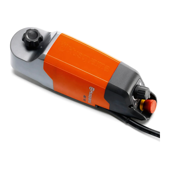
- Page 1 Workshop manual AD10...
- Page 2 Technical data Feature Data Model AD10 Motor power, W Weight, kg Max. drill diameter, mm Feed rate, m/min 3,2 (DS50–70) | 3,0 (DS450) Power supply 230 V, 50/60Hz 110 V, 50/60Hz Current limit, A 1,25...
- Page 3 HUSQVARNA CONTENT Page AD10 1. Introduction Spare parts 2. Service guide & troubleshooting Tightening torque 3. Safety & symbols General precautions Occurring symbols in the manual 4. Components – orientation Basic functional components Components – overview 5. Gear house Dismantling drive bearings Reassembling 6.
- Page 5 Spare parts IPL DOCUMENT This document comprises all spare parts for the automatic drill feeder AD10: art. No: 577 02 90–01 All components are illustrated in exploded views of the entire machine, where each compon...
- Page 7 Service guide & troubleshooting 2.Service guide & troubleshooting Troubleshooting and suggested actions 1. Machine does not start (no led nor feeding function) Action at customer 1. Connect unit to earthed outlet with residual-current device (RCD). 2. Check that emergency stop is out and try to start the machine by means of the On/Off button on the control panel. 3.
- Page 8 2. Check; that the PRCD of the drill motor is activated (press reset), check that the drill motor is switched on. 3. Connect drill motor directly to power outlet (not via the automatic drill feeder AD10). 4. If drill motor only works when connected directly to power outlet, send machine to service workshop.
- Page 9 Service guide & troubleshooting Tightening torque Torque for occurring metric fasteners (Nm±5%) Where otherwise not stated, all fasteners should be tightened with torque according to this table: Strength class 8.8 Strength class 10.9 SS-EN 29898-1 SS-EN 29898-1 metric coarse pitch threads metric coarse pitch threads Screw head Hex FZB...
- Page 11 Safety & symbols 3.Safety & symbols General precautions READ THE OPERATOR'S MANUAL • Familiarize yourself with the machine. Read the operator's manual. • The user's manual contains much information concerning basic service and main tenance, which is important in order to keep the machine safe and reliable. WARNING •...
- Page 12 Safety & symbols Occurring symbols in the manual Several graphical symbols are inserted in the manual's illustrations as simple means to better show details on actions to be taken, thus reducing the need to read through too much text. Chemical substances When performing service tasks involving the use of THREAD-LOCK COMPOUND...
- Page 13 Components – orientation 4.Components – orientation Basic functional components A) Power cable with Y-branch • For power mains connection 230V/(110V) with Y-branch for control of connected drill unit B) Control panel • Control buttons with LED indicat C) Machine body •...
- Page 14 Components – overview Machine overview 1. Power outlet 230V/110V), for drill ma chine connection: • Supplies power switch functionality for drill machine via AD10 2. Y-branch, power connection to: • Power mains, 230V/(110V) • Outlet for drill machine connec tion 3.
- Page 15 Gear house 5.Gear house 2,5mm Dismantling ×4 GEAR HOUSE LID AND AIR VALVE 1. Remove the following: (a) each of the four fasteners – 2,5mm Allen wrench (b) air valve • check O-ring: – replace if worn or cracks are vis ible 2.
- Page 16 Gear house DRIVE SHAFT 1. Knock out the drive shaft – use a rubber mallet 2. Remove drive shaft with the following parts: (a) exterior drive bearing (b) shaft spring (c) drive shaft – Reassembling: apply lubricator grease (G) along the entire drive shaft – see chap.
- Page 17 Gear house Continues from previous page INTERIOR BEARING 6. Dismantling of interior drive shaft bear • internal bearing puller Ø 14— 19mm 7. Pull out interior bearing Reassembling Start by joining the crown wheel and drive shaft bearing. REASSEMBLING DRIVE SHAFT BEARING 1.
- Page 18 Gear house FIXATE INTERIOR DRIVE SHAFT BEARING Crown wheel with mounted drive shaft bear ings is fixated inside the gear house 1. Use the drive shaft as support by fixing it in a vice (a) fixate drive shaft vertically (b) lower gear house on to the drive shaft 2.
- Page 19 Control panel and motor cover 6.Control panel and motor cover CONTROL PANEL ×2 1. Remove the two fasteners – Allen key: 3mm 2. Disconnect the following cables: (a) cables for the potentiometer (b) flat cable for On/Off button and – pull the cable contactor with long nose pliers Emergency stop button 3.
- Page 21 Dismantling motor unit and power cable 7.Dismantling motor unit and power cable Preparations First, dismantle control panel and motor cover according to previous chapter. SEPARATE MOTOR UNIT FROM GEAR HOUSE 1. Remove the fasteners, one in each corner: PE. Power cable to earth (yellow/green) –...
- Page 23 Electronics & circuit board 8.Electronics & circuit board Preparations Start by separating motor unit from gear house, see chapter 7, “Dismantling motor unit...”. Cooling fan 1. Connection to circuit board (a) cooling fan Also remove these for better access: (b) red, machine motor cable (c) blue, machine motor cable 2.
- Page 24 Electronics & circuit board Preparations Start by separating motor unit from gear house, see chapter 7, ”Dismantling of motor unit...”. Circuit board This is mounted on a cooling plate that is at tached to each end of the motor unit: 1.
- Page 25 Electronics & circuit board Electric diagram...
- Page 27 Pinion & machine motor 9.Pinion & machine motor Pinion and machine motor unit are supplied as one spare part unit and thus these steps are rarely necessary. Preparations Start by separating motor unit from gear house, see chapter 7, “Disassembling of motor unit...”...
- Page 28 Pinion & machine motor Assembling the pinion Assemble the pinion as follows: 1. Press pinion inside pinion bearing – a sturdy vice with aluminium jaws will do 2. Align and knock pinion coupling in position: • fit pinion with pinion bearing in a vise •...
- Page 29 Pinion & machine motor Pinion and machine motor with cooling block are supplied as a complete spare part Therefore the following steps are rarely needed. Motor Preparations: disassemble pinion unit follow ing step 1—2 in the beginning of this chapter. DISASSEMBLE AN OLD MOTOR Disassemble cooling unit ×4...
- Page 31 Tools ● = Service action 10.Tools Recommended tools BEARING AND GEAR (CHAPTER 5) ELECTRICS (CHAPTER 6—8) Universal puller Side cutter ● Dismantling of bearings in the ● Cutting of cables and cable ties gear house Internal bearing puller 6—10, 10—14, 14—19 (mm) Cable pliers ●...
- Page 33 CONTROL SYSTEM This chapter describes how to upgrade the machine firmware in the circuit board. The control system of a Husqvarna AD10 comprises the following: A) Drill feeder containing circuit board (H-bridge) with micro controller (ATMega 328P) that controls the behaviour of the connected drill machine.
- Page 34 PROGRAMMING UNIT: AVRISP MKII Complete service kit for programming comprising hardware and software can be ordered via Husqvarna support site. To obtain the hardware by other means, do as follows: • Use a 6-pin flat cable • Connect to the H-bridge card (contact CN3 for male: Tyco 7–215083–6) •...
- Page 36 www.husqvarnacp.com English 2011-10 1154414-26...