Table of Contents
Advertisement
Advertisement
Table of Contents

Related Manuals for Airlink101 AICN500


Summary of Contents for Airlink101 AICN500
- Page 1 SkyIPCam500 Night Vision Network Camera Model # AICN500 User’s Manual Ver. 1.0...
-
Page 2: Table Of Contents
CHAPTER 1 ... 2 INTRODUCTION TO YOUR CAMERA ... 2 1.1 Checking the Package Contents ... 2 1.2 Getting to Know Your Camera... 2 1.3 Features and Benefits ... 3 1.4 System Requirements ... 4 CHAPTER 2 ... 5 HARDWARE INSTALLATION ... 5 2.1 Installing the Camera Stand ... -
Page 3: Chapter 1
HAPTER NTRODUCTION 1.1 Checking the Package Contents Check the items contained in the package carefully. You should have the following: One SkyIPCam500 Night Vision Network Camera. One AC Power Adapter. One Camera Stand. One Ethernet Cable (Cat.5). One Installation CD-ROM. One Quick Installation Guide. -
Page 4: Features And Benefits
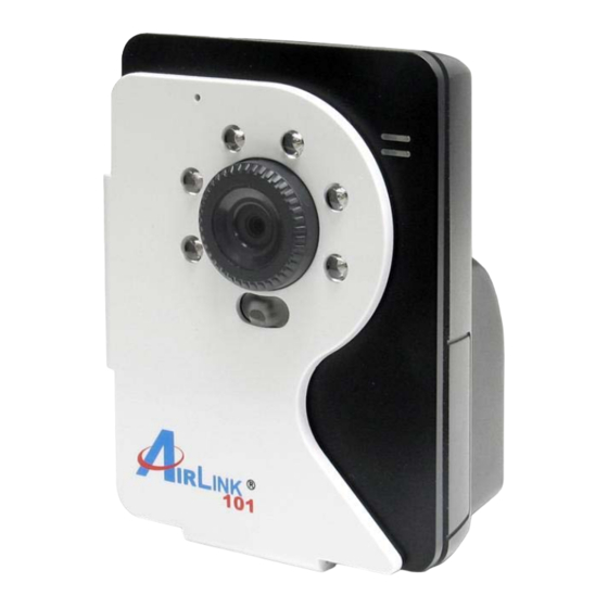
Screw Hole is used to connect the camera stand. DC Power Connector is used to connect the power adapter, in order to supply power to the camera. Reset Button will restart the camera when it is pressed quickly; when it is long pressed for ten seconds, the camera will be reset to the factory’s default... -
Page 5: System Requirements
Multiple Applications Supported With remote access technology, you can use the cameras to monitor various objects and places for your own purposes. For example, babies at home, patients in the hospital, offices and banks, and so on. The camera can capture both still images and video clips, so that you can keep the archives and restore them at any time. -
Page 6: Chapter 2
HAPTER ARDWARE NSTALLATION 2.1 Installing the Camera Stand The camera comes with a camera stand, which uses a swivel ball screw head to lock to the camera’s screw hole. When the camera stand is attached, you can place the camera anywhere by mounting the camera through the three screw holes located in the base of the camera stand. -
Page 7: Applications Of The Camera
Connecting the Ethernet Cable 2.3 Applications of the Camera The camera can be applied in multiple applications, including: Monitor local and remote places and objects via Internet or Intranet. Capture still images and video clips remotely. Upload images or send email messages with the still images attached. The following diagram explains some of the typical applications for your camera and provides a basic example for installing the camera. -
Page 8: Chapter 3
HAPTER OFTWARE NSTALLATION 3.1 Installing SkyIPCam Utility Step 1 Insert the provided CD and wait for the auto-run screen to appear. Step 2 Click on Install SkyIPCam Utility. Note: If the autorun screen does not appear automatically, go to Start, Run, type D:\ Utility\Setup.exe (where D is the letter of your CD drive) and click OK. -
Page 9: Using Skyipcam Utility
3.2 Using SkyIPCam Utility Step 1 Go to Start > (All) Programs > AirLink101 > AirLink101 SkyIPCam Utiliy Step 2 Select the IP Camera you want to configure from the list and click on the Change IP button. Note: If the Camera’s IP address does not show up in the window, make sure the camera is properly connected to the same network as your computer is, and then click on the Search button. - Page 10 Step 3 You may simply accept the suggested Static IP, or you can manually change the last 3-digit number of the IP Address, in case that the suggested one has already been used by another device in the same network. Another option is that if your router’s DHCP server is enabled, you can select DCHP, so the router will automatically assign a dynamic IP address to your camera.
- Page 11 Step 5 When you are prompted for the username and password, enter “admin” for both User name and Password, and click OK. Step 6 The camera viewing window will appear. Click on Setup, and then click Smart Wizard. Step 7 Enter a name for your camera and a location if you like.
- Page 12 Step 8 You may also change the camera’s IP settings in the below window, and click Next. Step 9 If you would like to set up email alerts that you can receive in the future, Please enter your email information here. You can get this information from your internet service provider. If you want to set this up at a later time, click Next.
- Page 13 Step 10 Confirm your settings at the last window. If everything is correct, click Apply and the configuration is complete. - 12 -...
-
Page 14: Viewing Images
3.3 Viewing Images Method 1 --- Access from Web Browser Step 1 If you know the IP address of your network camera, you may open the Web Browser on your computer. Step 2 Type the IP address of your camera (the default IP is 192.168.1.240) in the Address bar, and then press [Enter]. - Page 15 Step 5 Click on Install, and then you may be able to view images. Step 6 To get a clear view of images, you can simply rotate the camera’s lens clockwise or counter- clockwise to adjust the focus. - 14 -...
-
Page 16: Using Skyipcam View
Method 2 --- Access from SkyIPCam Utility Step 1 Go to Start > (All) Programs > AirLink101 > AirLink101 SkyIPCam Utiliy, and open the Airlink101 SkyIPCam Utility. Step 2 Select your camera from the list and click Link Step 3 Follow Step 3 to Step 6 mentioned in Method 1. - Page 17 Step 2 Keep clicking Next on the following windows. Step 3 Click Close to complete the installation. - 16 -...
- Page 18 To Launch the Program This section describes the user interface and operating instructions of SkyIPCam View. To launch the program, click Start > Programs > AirLink101 > AirLink101 SkyIPCam View, and the main screen will appear as below: NOTE Please set the resolution to 1024x768 or above on your computer while using SkyIPCam View; otherwise, the displayed main screen may be distorted.
- Page 19 CONTROLS Panel - SETTING: Click to enter the Setting screen of SkyIPCam View. Click again to return to the main screen of SkyIPCam View. - PLAY: Click to play the recorded video file using the media player on the computer (for example, Windows Media Player by default).
- Page 20 VIEW SELECTION Panel - View mode buttons: SkyIPCam View provides multiple view modes, including 1/4/9/16 windows and Full screen mode. - SCAN: When you connect multiple cameras, click this button to display the video views as the main window in turn. - PREV: When you connect multiple cameras, click this button to switch the video view to the previous camera.
- Page 21 CAMERA Panel - TRIGGER OUT: Click to turn on the trigger out connector of the camera. This button is available only when the connected camera supports the trigger out connector, which is used to control the external device connected to the camera, such as a light. - SNAPSHOT: Click to capture a still image using the selected camera and save the file in the computer.
- Page 22 SYSTEM Panel This panel displays the current date and time. PAN-TILT CONTROL Panel (optional) When you connect a pan/tilt camera, the system will detect the camera’s function automatically and the PAN-TILT CONTROL buttons will become functional. Otherwise, these buttons are displayed as gray out buttons.
- Page 23 To Add a Camera 1. Click SETTING in the CONTROLS panel to display the Setting screen. 2. Click Add New Camera. 3. In the pop-up Add New Camera dialog window, you can: Select the Search tab if you are not sure of the camera’s IP address. Click Search camera to search the available camera within the network.
- Page 24 4. Enter the User name and Password for the camera, and then click OK. The connected camera will be displayed in the Camera List. 5. Click SETTING to return to the Video View Window. The video view of the selected camera will be displayed now.
- Page 25 To Link to the Web Page of the Camera Click SETTING > Camera List > Camera Configuration and then Link web page to launch the Web browser that displays live view image and Web Configuration of the selected camera. To Record Video SkyIPCam View provides three methods to record video clips: one is to click the RECORD/ALL RECORD button to record manually;...
- Page 26 Schedule recording This recording method will work after you have completed the required settings in Schedule Recording Configuration. The recording schedule can be defined by Schedule Period or Recording Time. - Schedule Period: First, select the camera from the pull-down list. Then, click Add to set the Start/Stop date and time and then click OK to add the recording schedule to the list.
- Page 27 - Recording Time: First, select the camera from the pull-down list and select Recording time tab. Then, select the weekday from the day buttons and then set the time period. Click Apply to save the settings. To Configure the Recording Settings To configure the recording settings, including the storage folder and storage options, click SETTING >...
- Page 28 To Playback the Recorded Video The recorded video clips are saved in your computer, and can be played using the media player on the computer, such as Windows Media Player. To start playback, simply click the PLAY button on the CONTROLS panel, and the following dialog screen will appear, allowing you to select the file to playback.
- Page 29 To Set up Motion Detection Options When the motion detection function of the selected camera is enabled, you can set the Motion Options by selecting Alarm, Recording, Send e-Mail, and Trigger Out under SETTING > Motion Configuration. Alarm: Select Beep or Music to alert you for the motion detected. When you select Music, you can customize the sound by clicking Browse and then selecting your favorite music (*.wav or *.mp3 file) in the computer.
- Page 30 - Mail From: Enter the email address of the user who will send the email. For example, John@mymail.com. - Mail To: Enter the email address of the user who will receive the email. - User Name: Enter the user name to login the mail server. - Password: Enter the password to login the mail server.
- Page 31 Other Allows you to set the rotation interval if monitoring multiple cameras. - 30 -...
- Page 32 Information Click SETTING > About to display the information of the software application. - 31 -...
-
Page 33: Chapter 4
HAPTER ONFIGURATION 4.1 Using the Web Configuration You can access and manage the camera through the Web browser and the provided software application SkyIPCam View. This chapter describes the Web Configuration, and guides you through the configuration of the camera by using the web browser. To configure the camera, click Setup on the main page of Web Configuration. - Page 34 Basic >> Date & Time Date & Time - TimeZone: Select the proper time zone for the region from the pull-down menu. - Synchronize with PC: Select this option and the date & time settings of the camera will be synchronized with the connected computer.
-
Page 35: Network Settings
When you are finished, click Add/Modify to add the new user to the camera. To modify the user’s information, select the one you want to modify from UserList and click Add/Modify. - UserList: Display the existing users of the camera. To delete a user, select the one you want to delete and click Delete. - Page 36 Network >> Network IP Setting This item allows you to select the IP address mode and set up the related configuration. - DHCP: Select this option when your network uses the DHCP server. When the camera starts up, it will be assigned an IP address from the DHCP server automatically. It is recommended that you NOT use DCHP.
-
Page 37: Setting Up Video & Audio
- HTTP Port: The default HTTP port is 80. Some ISP’s have port 80 blocked. If you are having problems, you can change it to some other port. The suggested port to be used is anything between 1024 to 65535 Network >>... - Page 38 Image Setting - Brightness: Adjust the brightness level from 0 ~ 100. - Contrast: Adjust the contrast level from 0 ~ 100. - Saturation: Adjust the colors level from 0 ~ 100 Click Default to restore the default settings of the three options above. - Mirror: Select the Horizontal option to mirror the image horizontally.
- Page 39 Video & Audio >> Video MJPEG - Video Resolution: Select the desired video resolution from the three formats: VGA, QVGA and QQVGA. The higher setting (VGA) obtains better video quality while it uses more resource within your network. QQVGA is the lowest video quality setting but it provides the best speed over the network.
-
Page 40: Event Server Configuration
Video & Audio >> Audio Camera Microphone In Select the Enable option to enable the camera’s audio function, so that you can receive the on-site sound and voice from the camera. 4.5 Event Server Configuration The Event Server menu contains two sub-menus that allow you to upload images to FTP, and send emails that include still images. -
Page 41: Motion Detect
Event Server Setting>> FTP - Host Address: Enter the IP address of the target FTP server. - Port Number: Enter the port number used for the FTP server. - User Name: Enter the user name to login into the FTP server. - Password: Enter the password to login into the FTP server. -
Page 42: Event Configuration
- Name: Assign a name to the detecting area. - Threshold: Move the slide bar to adjust the level for detecting motion to record video. 4.7 Event Configuration The Event Configuration menu contains four sub-menus that provide the commands to configure event profiles. - Page 43 the profile is added to the Schedule Profiles list. To delete the profile, select the profile in the list and click Delete. - Profile Name: Display the profile name that you select in the Schedule Profiles list. - Weekdays: Select the weekday(s) that you want to separately assign in the schedule profile. The weekday that has been assigned will be displayed with green color.
-
Page 44: Tools
Event Configuration >> Schedule Trigger You can separately configure the schedule for trigger function of the camera by Email, or FTP. Select the Enable option on each item, and then select a Schedule Profile from the pull-down list and set the Interval time. -
Page 45: Information
Factory Reset Click Reset to restore all factory default settings for the camera. System Reboot Click Reboot to restart the camera just like turning the device off and on. The camera configuration will be retained after rebooting. Configuration You can save your camera configuration as a backup file on your computer. Whenever you want to resume the original settings, you can restore them by retrieving the backup file. - Page 46 System Log The Logs table displays the events log recorded by the system. - 45 -...
-
Page 47: Chapter 5
HAPTER PPENDIX A.1 Specification Image Sensor Sensor 1/4” color CMOS Resolution 640x480 Video Compression MJPEG Video resolution VGA/QVGA/QQVGA; 30fps max. System Hardware Processor ARM9 base 16MB SDRAM 4MB NOR Flash Power DC 5V Communication 10/100Mbps Fast Ethernet, auto-sensed, Auto-MDIX Protocol support TCP/IP, UDP, ICMP, DHCP, NTP, DNS, DDNS, SMTP, FTP, PPPoE, UPnP User Interface One RJ-45 port Reset... -
Page 48: Glossary Of Terms
- Storage: 0% ~ 90% non-condensing FCC Class B, CE Class B A.2 Glossary of Terms NUMBERS 10BASE-T 10BASE-T is Ethernet over UTP Category III, IV, or V unshielded twisted-pair media. 100BASE-TX The two-pair twisted-media implementation of 100BASE-T is called 100BASE-TX. ADPCM Adaptive Differential Pulse Code Modulation, a new technology improved from PCM, which encodes analog sounds to digital form. - Page 49 automatically assigns an IP address to any device that requests one. Domain Name System is an Internet service that translates domain names into IP addresses. Since domain names are alphabetic, they're easier to remember. The Internet however, is really based on IP addresses every time you use a domain name the DNS will translate the name into the corresponding IP address.
- Page 50 IP address IP address is a 32-binary digit number that identifies each sender or receiver of information that is sent in packets across the Internet. For example 80.80.80.69 is an IP address. When you “call” that number, using any connection methods, you get connected to the computer that “owns”...
- Page 51 Protocol Communication on the network is governed by sets of rules called protocols. Protocols provide the guidelines devices use to communicate with each other, and thus they have different functions. Some protocols are responsible for formatting and presenting and presenting data that will be transferred from file server memory to the file server’s net work adapter Others are responsible for filtering information between networks and forwarding data to its destination.
- Page 52 User Name The USERNAME is the unique name assigned to each person who has access to the LAN. Utility It is a program that performs a specific task. Unshielded twisted-pair. UTP is a form of cable used by all access methods. It consists of several pairs of wires enclosed in an unshielded sheath.
-
Page 53: Technical Support
* Actual data throughput will vary. Network conditions and environmental factors lower actual data throughput rate. Specifications are subject to change without notice. All products and trademarks are the property of their respective owners. Copyright ©2008 AirLink101® Technical Support E-mail: support@airlink101.com Toll Free: 1-888-746-3238 Web Site:...