Table of Contents
Advertisement
Quick Links
Advertisement
Table of Contents

Related Manuals for Horizon Fitness H-1000


Summary of Contents for Horizon Fitness H-1000
- Page 1 H-1000 Fuel Cell Stack User Manual Updated 18 May 2011 H-1000_UM_V4.4_EN...
- Page 2 It is the responsibility of the customer to meet all local safety requirements and to ensure safety during operation, maintenance and storage of the H-1000 stack. Although all efforts have been made to ensure the accuracy and completeness of the information contained in this document, Horizon reserves the right to change the information at any time and assumes no liability for its accuracy.
-
Page 3: Table Of Contents
3. Stack and System Component Information........4. Technical Specifications..............5. System Set Up.................. 6. Notes for the set up ................7. System Setup Diagram ..............8. Operating Procedure................ 9. Polarization Curves................10. Storage and Re-use................11. Troubleshooting&System Checks............12. Fuel Cell Drawing................13. FAQ....................H-1000 Fuel Cell Stack User Manual V4.4... -
Page 4: Safety
There are no warnings before unconsciousness results. When operating the stack in an enclosure: • Ensure ventilation slots are clear and unobstructed at all times during operation. • Operate within the temperatures limits stated in the manual. • Never operate if an alarm condition exists. Note: We highly recommend customer use a hydrogen sensor(not provided) to detect the hydrogen leakage. H-1000 Fuel Cell Stack User Manual V4.4... - Page 5 As a preventative measure, the stack must be operated in a well-ventilated area in order to inhibit potential hydrogen accumulation. WARNING! Always operate the stack in a well-ventilated area and ensure that ventilation slots are unobstructed. H-1000 Fuel Cell Stack User Manual V4.4...
- Page 6 As a preventative measure, the stack must be operated in a well-ventilated area in order to compensate for the oxygen used within the fuel cells. WARNING! Always operate the stack in a well-ventilated area. H-1000 Fuel Cell Stack User Manual V4.4...
- Page 7 Always assume that the fuel cell stack is charged. Jewellery (such as rings, necklaces, bracelets and watches) may concentrate an electric current when it comes into contact with charged components, or when a shock passes through the human body. Accordingly, no jewellery should be worn near the stack. WARNING! Do not wear jewellery near the stack. H-1000 Fuel Cell Stack User Manual V4.4...
- Page 8 55ºC and the cooling air stream can reach 17ºC above ambient conditions. These temperatures are sufficient to cause burns or severe discomfort. Accordingly, avoid contact with the fuel cell stack, or components that convey process or cooling air. WARNING! Avoid contact with the fuel cell stack or components that convey process or cooling air. H-1000 Fuel Cell Stack User Manual V4.4...
-
Page 9: Terminology
Blower: supply air to the fuel cells and meanwhile decrease the temperature in the stack. Mass flow per minute: the total amount of the hydrogen flow through the fuel cell every minute, which the hydrogen supply can be calculated. HFCT: Horizon Fuel Cell Technologies H-1000 Fuel Cell Stack User Manual V4.4... - Page 10 A: Hydrogen Inlet connector B: Blower C: Hydrogen Outlet connector D: Supply valve E: Purge valve H-1000 Fuel Cell Stack User Manual V4.4...
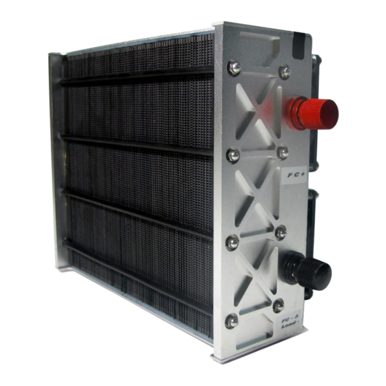
- Page 11 A: Lable (FC- and Load-) B: FC- and Load- connecter C: FC+ connecter D: Lable (FC+) E: Warning Labels H-1000 Fuel Cell Stack User Manual V4.4...
- Page 12 D: Connect plug E: SCU(short circuit units) switch F: ON/OFF button G: Connect to FC+ H: Connect to FC- I: Connect to Load+ J:Controller power supply DC 13V+ K:Controller power supply DC 13V- H-1000 Fuel Cell Stack User Manual V4.4...
-
Page 13: Stack And System Component Information
It is the switch of the controller. Hold it for 2 seconds for either on or off. 5. Blower Supply air to the fuel cells and meanwhile decrease the temperature in the stack. H-1000 Fuel Cell Stack User Manual V4.4... - Page 14 The tube with 6mm outer diameter and 3mm inner diameter is connected to the H2 Inlet and outlet as in 9 above and to the input valve and output valve of the hydrogen source. 11 . Fittings For connecting the load. H-1000 Fuel Cell Stack User Manual V4.4...
-
Page 15: Technical Specifications
#3 & #7 Blowers (Red= +ve, Black= -ve) Blowers signal Blowers power The blower is PWM control, so it needs pins #9 & #10 to give the signal to the control blowers power. H-1000 Fuel Cell Stack User Manual V4.4... -
Page 16: System Set Up
30cm. The inner diameter of the tube is required to be more than 2mm. STEP1: Connect the connectors of the controller and the stack to get the blower, the temperature sensor, the hydrogen supply valve and the purge valve under control. The finished connection is shown in H-1000 Fuel Cell Stack User Manual V4.4... - Page 17 STEP2: Connect the controller and the stack as the output power also should be under control. The finished connection is shown in 2E. H-1000 Fuel Cell Stack User Manual V4.4...
- Page 18 Connect the output of the hydrogen supply valve to the stack (see the arrow on the valve). The hydrogen supply valve will prevent damage from the hydrogen while the stack is off. Pay attention to the direction of the connection of the Hydrogen supply valve. The finished connection is shown in 5H. H-1000 Fuel Cell Stack User Manual V4.4...
- Page 19 H-1000 Fuel Cell Stack User Manual V4.4...
- Page 20 Note: The tube between stack output and purging valve is required to be less than 20cm. The tube connected to the purging valve output is required to be less than 30cm. The inner diameter of the tube is required to be more than 2mm. H-1000 Fuel Cell Stack User Manual V4.4...
- Page 21 STEP7: Check all the connection first and connect the load to the system, Load+ is linked to the "load+" at the controller, Load- links to the "FC- and load-" in the stack shown in 7A STEP8: Provide hydrogen and stabilized voltage first and then press the ON/OFF switch to start the system. H-1000 Fuel Cell Stack User Manual V4.4...
- Page 22 The 8pin plug connection between the stack and the controller. 6. The "FC+/-" connection between the stack and controller. The input hydrogen pressure is 0.45-0.55Bar. The external battery is providing 12-14V. The load is below 1000W. The System is now setup and ready to be used. H-1000 Fuel Cell Stack User Manual V4.4...
-
Page 23: Notes For The Set Up
30cm. The pressure of the hydrogen is between 0.45--0.55Bar. The load connecter, load+, is connected to the "load +"in the controller. Connected the load- to "FC- & Load-" in the stack. H-1000 Fuel Cell Stack User Manual V4.4... - Page 24 20cm. The tube connected to the purging valve output is required to be less than 30cm. The inner diameter of the tube is required to be more than 2mm. H-1000 Fuel Cell Stack User Manual V4.4...
-
Page 25: System Setup Diagram
7. System setup diagram SCU: Short Circuit Unit GND: Grounding H-1000 Fuel Cell Stack User Manual V4.4... -
Page 26: Operating Procedure
If you do not hear the hissing from the purge valve review “Checking the Valve” in Troubleshooting. Following the purging the fuel cell will short circuit 5 times over a 10 seconds period. If you cannot hear the 5 short circuits review “Check the SCU” in Troubleshooting. H-1000 Fuel Cell Stack User Manual V4.4... - Page 27 Make sure you the orientation of the fuel cell is kept the same during operation as shown on the fuel cell stack with the sticker “This side up”. Do not move the fuel cell around or shake vigorously during operation. If the system shuts down during running procedure, review the Bleeping interpretation during running procedure. H-1000 Fuel Cell Stack User Manual V4.4...
- Page 28 If will not be using the fuel cell, please follow these final steps. Disconnect the external power supply from the controller. Completely disconnect the fuel cell system from the load. Completely disconnect the fuel cell system from the controller. Let the fuel cell cool down before placing it into an air tight container. This will help to maintain its performance particularly during long periods of storage. H-1000 Fuel Cell Stack User Manual V4.4...
-
Page 29: Polarization Curves
Performance characteristics of the stack are presented. All performance data is given for baseline operating conditions, defined at sea-level and room ambient temperature. H1000 U-I curve H1000 U-I curve H1000 H2 flow 16000 14000 12000 10000 8000 6000 4000 2000 1000 1200 H1000 H2 f low H1000 P-I Curve 1200 1000 H1000 P-I Curve H-1000 Fuel Cell Stack User Manual V4.4... -
Page 30: Storage And Re-Use
45˚C, the whole system will stop operation in order to protect the stack. So in order to make it work well, the fuel cell stack must be maintained lower than 45˚C before operate the on/off switch. 5. The stack must be standing on the clear plastic feet. H-1000 Fuel Cell Stack User Manual V4.4... -
Page 31: Troubleshooting&System Checks
Make sure the hydrogen supply pressure is 0.45-0.55Bar. WARNING: 1. Please make sure you have purged the water out of the stack thoroughly before use. 2. Using the fuel cell stack with water inside can irreparably damage it! H-1000 Fuel Cell Stack User Manual V4.4... - Page 32 No. of Bleeps Interpretation Action High current protection i.e. current is too high - For H-100 - H-300 is > 12A set by the controller. - For H-500 - H-1000 is > 30A set by the controller. High temperature fuel cell protection i.e. fuel cell is running >65˚C. Low voltage fuel cell protection i.e. the average voltage per cell is <0.5V Note: If one of the above situations occurs, the stack will disconnect the load and make an alarm.
- Page 33 Input pressure is 0.45-0.55Bar. If both valves open, system will follow normal start up procedures. If either of the valves still don’t open. Check the controller section on Valves in Trouble shooting. H-1000 Fuel Cell Stack User Manual V4.4...
- Page 34 Check your external power supply, to see how much current is being drawn during the starting time, it should be more than 0.6A for 3 seconds.Check the external power supply H-1000 Fuel Cell Stack User Manual V4.4...
-
Page 35: Fuel Cell Drawing
12. Fuel Cell Drawing H-1000 Fuel Cell Stack User Manual V4.4... -
Page 36: Faq
This is the Short Circuit Unit, it helps to condition the fuel cell for long term good performance. What is the Hydrogen pressure supplied to the fuel cell stack? The pressure is required to be 0.45-0.55Bar. H-1000 Fuel Cell Stack User Manual V4.4...