Dovre VINTAGE 35GA Installation Instructions And Operating Manual
Hide thumbs
Also See for VINTAGE 35GA:
- Installation instructions and operating manual (294 pages) ,
- Installation instructions and operating manual (307 pages)
Table of Contents
Advertisement
Quick Links
INSTALLATIEVOORSCHRIFTEN EN GEBRUIKSAANWIJZING
INSTALLATION INSTRUCTIONS AND OPERATING MANUAL
INSTALLATION ET MODE D'EMPLOI
EINBAUANLEITUNG UND GEBRAUCHSANWEISUNG
INSTRUCCIONES DE INSTALACIÓN Y USO
ISTRUZIONI PER L'INSTALLAZIONE E L'USO
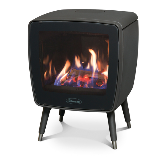
VINTAGE 35GA
VINTAGE 35GAP
Type C11
Type C31
Type C91
GASKACHEL
GAS STOVE
POELE A GAZ
GASOFEN
ESTUFA DE GAS
STUFA A GAS
VINTAGE 50GA
VINTAGE 50GAP
03.27126.200 - 07/2014
Advertisement
Table of Contents

Related Manuals for Dovre VINTAGE 35GA


Summary of Contents for Dovre VINTAGE 35GA
- Page 1 INSTALLATION ET MODE D’EMPLOI GASOFEN EINBAUANLEITUNG UND GEBRAUCHSANWEISUNG ESTUFA DE GAS INSTRUCCIONES DE INSTALACIÓN Y USO STUFA A GAS ISTRUZIONI PER L'INSTALLAZIONE E L'USO VINTAGE 35GA VINTAGE 50GA VINTAGE 35GAP VINTAGE 50GAP Type C11 Type C31 Type C91 03.27126.200 - 07/2014...
-
Page 2: Table Of Contents
Table of contents Introduction Declaration of conformity Safety Installation requirements General Concentric flue gas exhaust system Existing chimney Type C91 Floor and walls Product description Installation General preparation Preparing the connection to the flue Closed system connection Establishing a gas connection Installing the remote control set Placing decorative wood block set First use... -
Page 3: Introduction
Observe the following safety regulations when installing and using the appliance. In this manual, you can read how the DOVRE heating appliance can be installed, used and maintained safely. Should you require additional information or technical data, or should you experience an install- ation problem, please first contact your supplier. -
Page 4: Declaration Of Conformity
Vintage 35GA(P) and Vintage 50GA(P) gas accordance with the installation instructions of stoves are manufactured according to the EN 613. -
Page 5: Installation Requirements
bottom in the appliance. manufacturer Muelink & Grol. The appliance can also be connected to a concentric flue gas exhaust system The appliance must be inspected by the from the manufacturers Metaloterm or Poujoulat. Use installer for the air tightness of the gas supply the appropriate connection collar (available from your and flue gas duct. -
Page 6: Existing Chimney Type C91
The distance from ducts and sleeves to com- The pipe must have a diameter of at least 150 mm bustible material must be at least 50 mm every- round or square, and no more than 250 mm round or where. square along the entire length. -
Page 7: Product Description
Product description Installation General preparation Please check the appliance immediately after deliv- ery for damage during transport or any other dam- age or defects. The appliance is attached to the pallet with screws at the bottom. 09-20020-184 1. Mirror 2. Ceramic wood block set 3. - Page 8 09-20020-186 2. Remove the box with the wood block set and other parts included separately in the delivery from the appliance. 09-20020-185 3. Remove the burner (1) from the stove; see next fig- ure. The cast iron side panels can also be easily unhooked by loosening the top nut a bit;...
- Page 9 09-20020-188 09-20006-010 Take the distance from combustible material into account. See the appendix "Distance from com- bustible material". Determining the duct route 09-20020-189 Make a drawing of the route you want the concentric Placing the stove exhaust duct to follow. Check whether the duct route you want is per- Preferably place the stove on a flat floor.
-
Page 10: Preparing The Connection To The Flue
Positioning the restriction plate serves to Connecting to the top adjust the draft in the stove to the duct route selected. 1. Unscrew the connection collars (1) and (2) from the back of the stove; see next figure. The restriction plate can be placed in three pos- itions, marked with 1, 2 and 3;... -
Page 11: Closed System Connection
4. Install the cover plates (3) and (4) to the back of the stove. Install the smallest plate first. 5. Unscrew the round cover lid from the top plate. 6. Place the top plate back on the stove before the connection duct is installed. - Page 12 6. Extend the facade sleeve through the facade from pipe. You can also convert the existing pipe into a con- the outside, with the “TOP” up, connect to the con- centric pipe using a single-wall flexible hose and the centric elbow and attach it to the outside of the right pipe reducers.
- Page 13 concentric pipe at least 100 mm into the existing Flexible stainless steel 316L hose, single- flue. wall round diameter 100/107 mm (heat res- istance 600°C) The slide (4) should therefore extend about 200 Stainless steel hose clamp reach diameter mm into the inner duct of the top concentric 90 to 165 mm component.
-
Page 14: Establishing A Gas Connection
7. Slide the roof sheet (4) over the pipe and tighten it 6. Slide a roofing sheet for pitched roof (tar roof) or a with screws. lead slab (4) (tile roof) over the pipe and seal or cover it watertight. 8. -
Page 15: Installing The Remote Control Set
Installing the remote control set The Mertik Maxitrol GV60 remote control set consists of a handset (transmitter) and a receiver. The system works on batteries; connecting an AC adaptor is optional. The batteries (1 x 9 Volt block for the handset (transmitter), 4 x 1.5 Volt AA for the receiver) are not included in the delivery. -
Page 16: Placing Decorative Wood Block Set
The blocks are fragile, treat them with care. The blocks must be placed on the burner exactly as indicated in the photos. Vintage 35GA 09-20020-209 Follow the instructions below to place the blocks: 1. Place the first block at the back on the middle of... - Page 17 3. Place the third block at the front of the burner, When replacing the glass pane, check that the obliquely over the second block; see next figure. sealing profile is in the right place and fits prop- erly. The stove is now ready for use. Vintage 50GA Follow the instructions below to place the blocks: 1.
-
Page 18: Use
The appliance is now ready for use. First use When you use the appliance for the first time, run it at the highest setting for a few hours and ventilate the room adequately at the same time. This will cure the heat-resistant paint finish. -
Page 19: Switching Off The Stove
Continuous beeps confirm ignition of the stove. Flame height adjustment The main gas flow is available once the pilot is ignited. After the main burner is ignited, the handset will automatically switch over to the manual operation mode. If the pilot goes out after several attempts, switch the main valve button to OFF and follow the instructions under “Switch off gas to stove”. -
Page 20: Operating Methods
Operating methods 09-20020-221 09-20020-223 Double-click on (small flame). The letter com- bination LO is displayed. The operating mode changes as follows by briefly pressing SET: The flame first increases and then adjusts to the special low setting. MAN → TEMP → TEMP →... -
Page 21: C/24-Hour Or °F/12-Hour Clock Settings
09-20020-225 09-20020-226 The appliance must be in standby mode and the pilot The stove must be in standby mode and the pilot must flame must be lit**. be lit. The timers P1 and P2 (Programme 1, Programme 2) The room temperature is measured and compared to can each be programmed in such a way that they are the temperature programmed. -
Page 22: Time Settings
Press OFF and (small flame) until the Fahren- heit/12-hour-clock display changes to Celsius/24-hour clock and vice versa. Time settings 09-20020-229 1. Briefly press SET to enter the TEMP mode. 2. Continue pressingSET until TEMP flashes. 09-20020-228 The time indicator flashes after: a. - Page 23 09-20020-231 09-20020-233 4. Press (small flame) to lower the daytime 1. Briefly press SET to enter the TEMP mode. temperature setting. 2. Continue pressingSET until TEMP flashes. 09-20020-232 09-20020-234 5. Press OFF or wait until programming is finished. 3. Press (large flame) to raise the nighttime Setting the NIGHTTIME REDUCTION temperature...
-
Page 24: Programme Timer Settings
The time settings must be programmed in the fol- lowing sequence: ≤ P1 < P2 ≤ P2 . At P1 = P1 or P2 = P2 switches the timer off. Use the following setting so the stove stays lit at night: 23:50 and P1 0:00... - Page 25 09-20020-239 09-20020-241 1. Briefly press SET to go to P1 OFF time setting. 2. Press (large flame) to set the hour. (moon) appears and the time setting flashes. 09-20020-240 09-20020-242 3. Press (small flame) to set the minutes. P1 OFF time settings 2.
-
Page 26: Manual Operation
09-20020-243 09-20020-244 3. Press (small flame) to set the minutes. Piezo ignition P2 ON time setting On/off switch (option) 1. Briefly press SET to go to P2 OFF time setting. Eight-wire-receiver-contact (sun) appears and the time setting flashes. Microswitch 2. See instructions ''P1 ON time setting''. Piezo ignition connection (2.8x0.8mm) Manual button in MAN position P2 OFF time setting... -
Page 27: Switch Off Gas To Stove
Check by smell whether any gas is still present Combustion control around the stove, including near the floor. When the stove is still fairly cold, the flames of the If you detect any gas odour, stop immediately. main burner are very blue during ignition. As the stove See the last warning in the chapter “Safety”. -
Page 28: Cleaning And Other Regularly Maintenance
Check the remote control, replace the batteries if Do not use abrasive or aggressive products to necessary. clean the glass. Operation test: ignition of pilot flame, ignition of Wear household gloves to protect your hands. main burner, operation of the remote control. If the glass in the appliance is broken or cracked, it must be replaced before you can Access to the most important com-... -
Page 29: Spare Parts
Check whether the glass pane sealing rope is still in good condition and working well. The sealing rope is subject to wear and will need to be replaced in time. Spare parts Vintage 35GA(P) Description Part number Handset (i.e. transmitter) 03.06134.000... -
Page 30: Appendix 1: Technical Data
Appendix 1: Technical data Model Vintage 35GA ES GB IE Country BE FR GE LU PT DK FI SE IT AT Category I2E+ I2ELL Type of gas G20 / G25 Type of appliance C11 / C31 C11 / C31 C11 / C31... - Page 31 Model Vintage 35GAP BE GB IE PT NO DK FI SE Country DK FI SE IT AT DE NL Category I3B/P Type of gas G30/31 Type of appliance C11 / C31 C11 / C31 Nominal load 4.4 kW 4.4 kW Efficiency 78.8 % 78.8 %...
- Page 32 Model Vintage 50GA ES GB IE Country BE FR GE LU PT DK FI SE IT AT Category I2E+ I2ELL Type of gas G20 / G25 Type of appliance C11 / C31 C11 / C31 C11 / C31 C11 / C31 C11 / C31 Nominal load 8.7 kW...
- Page 33 Model Vintage 50GAP BE GB IE PT NO DK FI SE Country DK FI SE IT AT DE NL Category I3B/P Type of gas G30/31 Type of appliance C11 / C31 C11 / C31 Nominal load 6.0 kW 6.0 kW Efficiency 83 % 83 %...
-
Page 34: Appendix 2: Dimensions
Appendix 2: Dimensions Vintage 35GA(P) 09-20020-200 Subject to change because of technical improvements... - Page 35 Vintage 35GA(P)/TB 3/8" 09-20020-201 Subject to change because of technical improvements...
- Page 36 Vintage 35GA(P)/WB 3/8" 09-20020-202 Subject to change because of technical improvements...
- Page 37 Vintage 35GA(P)/CR 3/8" 09-20020-203 Subject to change because of technical improvements...
- Page 38 Vintage 50GA(P) 3/8" 09-20020-197 Subject to change because of technical improvements...
- Page 39 Vintage 50GA(P)/TB 3/8" 09-20020-198 Subject to change because of technical improvements...
- Page 40 Vintage 50GA(P)/WB 3/8" 09-20020-199 Subject to change because of technical improvements...
-
Page 41: Appendix 3: Distance From Combustible Material
Appendix 3: Distance from combustible material Vintage 35GA(P) - Minimal distance in millimetres Combustible material Incombustible material Subject to change because of technical improvements... - Page 42 Vintage 50GA(P) - Minimal distance in millimetres Combustible material Incombustible material Subject to change because of technical improvements...
-
Page 43: Appendix 4: Overview Of Concentric Flue Gas Exhaust Materials
Appendix 4: Overview of concentric flue gas exhaust materials Illustration Description Manufacturer part code Muelink Metaloterm Poujoulat &Grol 1000 mm duct 41.003.17.21 US 100 10 ED 1000 100 PGI 500 mm duct 41.003.17.20 US 50 10 ED 450 100 PGI 500 mm adaptor 41.003.17.22 USPP 10 ER 100 PGI... -
Page 44: Appendix 5: Calculation Sheet For Checking Projected Route
Appendix 5: Calculation sheet for checking projected route Follow the three steps below to check whether the desired route for the concentric chimney exhaust is permitted. 1. Sketch the desired route and use it as a basis for filling in the information required in the table below. You can disregard the actual roof or wall sleeve here. - Page 45 Restriction plate pos- Top con- Back connection Assessment of route ition (only for natural nection gas version) 2 ≤ R < 4 1 ≤ R < 3 route permitted Position 1 4 ≤ R < 9 3 ≤ R < 7 route permitted Position 2 9 ≤...
-
Page 46: Appendix 6: Diagnosis Diagram
Appendix 6: Diagnosis diagram Problem No spark Spark but no ignition When ignition button is released, pilot flame goes out Main burner does not ignite Whistling between high and low setting Disrupted flame effect Gas smell Smell of combustion gases in room Appliance goes out Remote control does not work possible... - Page 47 (continued) Problem Soot deposit on ther- Clean the thermocouple with a cloth. mocouple Thermocouple faulty Replace the thermocouple (*). No spark Spark but no ignition When ignition button is released, pilot flame goes out Main burner does not ignite Whistling between high and low setting Disrupted flame effect Gas smell Smell of combustion gases in room...
-
Page 48: Index
Index Connecting dimensions Connection collar for connection to chimney Connection to chimney AC adaptor at the top Adjustment back flame height Air leak Connection to the chimney to the back Appliance switch off Connection to the flue preparation Battery empty Damage type Determining a route... - Page 49 Flue gas exhaust sealing diameter 30-33 Manual operating mode Fuel Mertik Maxitrol necessary amount GV60 Mirror panel connection size 30-33 Nighttime reduction temperature mode initial pressure 30-33 Nominal load 30-33 switch off Nominal output 27, 30-33 type of gas 30-33 Nozzle Gas connection burr...
- Page 50 Removable parts removal Removal combustion control Mirror panels remove Walls Remove fire safety mirror panels Warning Resolving problems flammable materials Restriction plate gas smell Roof sleeve glass broken or cracked 4, 28 flammable material 13-14 hot surface pitched roof log set pilot flame requirements Sealing rope for door...