Raymarine AIS700 Installation Instructions Manual
Hide thumbs
Also See for AIS700:
- Installation instructions manual (52 pages) ,
- Installation instructions manual (68 pages) ,
- Quick start manual (2 pages)

Related Manuals for Raymarine AIS700


Summary of Contents for Raymarine AIS700
- Page 1 AIS700 Installation instructions English (en-US) Date: 08-2020 Document number: 87326-2 © 2020 Raymarine UK Limited...
- Page 3 Software updates Check the Raymarine® website for the latest software releases for your product. www.raymarine.com/software Product documentation The latest versions of all English and translated documents are available to download in PDF format from the website: www.raymarine.com/manuals.
-
Page 5: Table Of Contents
Chapter 2 Document and product information............13 2.1 Product documentation...................... 14 2.2 Applicable products......................14 Obtain MMSI (Maritime Mobile Service Identity) number............14 2.3 Compatible Raymarine displays ..................15 2.4 Compatible 3rd party displays..................17 2.5 Parts supplied ........................17 2.6 AIS overview ........................18 Chapter 3 Installation ......................19... - Page 6 7.1 AIS700 technical specification ..................52 Chapter 8 Technical support ..................53 8.1 Product returns process ....................54 8.2 Raymarine product support and servicing ..............54 8.3 Learning resources ......................56 Chapter 9 Spares and accessories ................57 9.1 Spares and accessories ....................58 9.2 SeaTalkng ®...
- Page 7 Appendix C NMEA 2000 supported PGNs ..............63 Appendix D AIS overview....................64...
-
Page 9: Chapter 1 Important Information
• Raymarine® recommends certified installation by a Raymarine® approved installer. A certified installation qualifies for enhanced product warranty benefits. Contact your Raymarine® dealer for further details, and refer to the separate warranty document packed with your product. -
Page 10: Service And Maintenance
Warning: FCC Warning (Part 15.21) Changes or modifications to this equipment not expressly approved in writing by Raymarine Incorporated could violate compliance with FCC rules and void the user’s authority to operate the equipment. Innovation, Science and Economic Development Canada (ISED) This device complies with License-exempt RSS standard(s). -
Page 11: Innovation, Sciences Et Développement Économique Canada (Français)
AIS disclaimer All information presented by the AIS700 is advisory only, as there is a risk of incomplete and erroneous information. By placing this product into service you acknowledge this and assume complete responsibility for any associated risks, and accordingly release Raymarine® and SRT Marine Systems plc from any and all claims arising from the use of the AIS service. -
Page 12: Warranty Registration
However, Raymarine® cannot accept liability for any inaccuracies or omissions it may contain. In addition, our policy of continuous product improvement may change specifications without notice. As a result, Raymarine® cannot accept liability for any differences between the product and this document. Please check the Raymarine® website (www.raymarine.com/manuals) to... -
Page 13: Chapter 2 Document And Product Information
Chapter contents • 2.1 Product documentation on page 14 • 2.2 Applicable products on page 14 • 2.3 Compatible Raymarine displays on page 15 • 2.4 Compatible 3rd party displays on page 17 • 2.5 Parts supplied on page 17 •... -
Page 14: Product Documentation
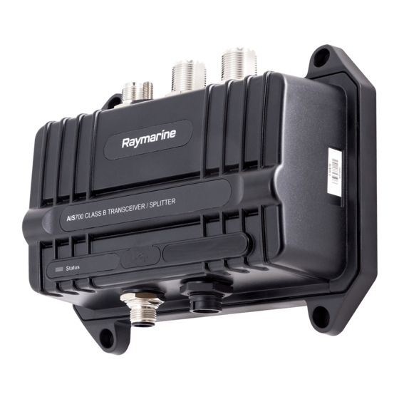
Description E70476 The AIS700 is a Class B AIS transceiver with a built-in VHF splitter, used to display real-time information on local vessels, land based stations or aids to navigation that are equipped with either Class A or Class B AIS transceivers. -
Page 15: Compatible Raymarine Displays
In the United States of America (USA), the MMSI and Static Data must be entered only by a Raymarine® dealer or other appropriately qualified installer of marine communications equipment for marine vessels. In the USA, the user is NOT authorized to do this. - Page 16 gS Series MFDs eS Series MFDs aSeries MFDs eSeries MFDs cSeries MFDs Compatible instrument displays Compatible instrument displays can be connected to the same SeaTalkng ® network. i70 Instrument display i70s Instrument display Compatible legacy MFDs SeaTalkng ® is the preferred method of connection for E-Series, C-Series, G-Series and A-Series MFDs, however NMEA 0183 can be used as an alternate connection if required.
-
Page 17: Compatible 3Rd Party Displays
AIS receiver/transceiver and the 3rd party display. 2.5 Parts supplied AIS700 unit. For an explanation of the warning symbol shown, refer to the Important Note below. 2. GNSS antenna, with captive cable 10m (33 ft). -
Page 18: Ais Overview
— Grounding 2.6 AIS overview Your AIS700 uses digital radio signals to exchange 'real-time' information between vessels, shore based stations, or aids to navigation (AToNs) on dedicated VHF frequencies. This information is used to identify and track vessels in the surrounding area and to provide fast, automatic and accurate collision avoidance data. -
Page 19: Chapter 3 Installation
Chapter 3: Installation Chapter contents • 3.1 Selecting a location on page 20 • 3.2 Mounting the AIS700 on page 22 • 3.3 Mounting the GNSS (GPS) antenna on page 23 Installation... -
Page 20: Selecting A Location
• Power supply — Select a location that is as close as possible to the vessel’s DC power source. This will help to keep cable runs to a minimum. • Diagnostics — The AIS700 must be mounted in a location where any diagnostics LEDs are easily visible. -
Page 21: Emc Installation Guidelines
Requirement for ferrites on non-Raymarine cables. If your product is to be connected to other equipment using a cable not supplied by Raymarine, a suppression ferrite MUST always be attached to the end of the cable nearest to the Raymarine product. -
Page 22: Compass Safe Distance
AIS700 dimensions 3.2 Mounting the AIS700 Before mounting the AIS700 ensure that you have: • selected a suitable location (a clear, flat surface is required). • Identified the relevant cable connections and the route that the cable will take. -
Page 23: Mounting The Gnss (Gps) Antenna
1. Using the AIS700 as a guide, mark the location of the mounting holes on the mounting surface. 2. Drill holes for the mounting fixings using a drill with a suitable sized drill bit. 3. Screw the fixings approximately half way into the holes in the mounting surface. -
Page 25: Chapter 4 Connections
Chapter 4: Connections Chapter contents • 4.1 Connections overview on page 26 • 4.2 USB connection on page 27 • 4.3 Power connection on page 28 • 4.4 NMEA 2000 / SeaTalkng ® connection on page 33 • 4.5 NMEA 0183 connection on page 33 •... -
Page 26: Connections Overview
4.1 Connections overview Connection Connects to: Suitable cables: GNSS connection GNSS antenna GNSS antenna’s fitted cable Vessel RF ground only. Grounding earth stud Grounding strap (not connection supplied). For more Important: You must information, refer to: make this connection for p.32 —... -
Page 27: Data Connections Matrix
As an example of how to use the table below, you can see that you can feed GNSS data into the AIS700 via a NMEA 0183 port configured for low baud rate (4,800), and then output it along with AIS data to the other NMEA 0183 port configured for high baud rate (38,400). -
Page 28: Power Connection
AIS unit 2. USB Micro-B to type A cable (not supplied) 3. PC (personal computer) running proAIS2 Note: • The PC USB connection will provide power to the unit to enable configuration prior to installation. • For details on configuring your unit, refer to: Chapter 5 Set up Warning: USB device power Do NOT connect any device to the product’s USB connection that requires an... -
Page 29: In-Line Fuse And Thermal Breaker Ratings
• The suitable fuse rating for the thermal breaker is dependent on the number of devices you are connecting. If in doubt consult an authorized Raymarine dealer. • Your product’s power cable may have an in-line fuse fitted, if not then you must add an in-line fuse / breaker to the positive wire of your product’s power connection. - Page 30 Positive (+) bar Negative (-) bar Circuit breaker Waterproof fuse holder containing a suitably-rated inline fuse must be fitted. In-line fuse and thermal breaker ratings For suitable fuse rating, refer to: Important: Observe the recommended fuse / breaker ratings provided in the product’s documentation, however be aware that the suitable fuse / breaker rating is dependent on the number of devices being connected.
- Page 31 Waterproof fuse holder containing a suitably-rated inline fuse must be fitted. In-line fuse and thermal breaker ratings For suitable fuse rating, refer to: Product power cable. Drain wire connection point. Battery connection scenario A: Suitable for a vessel with a common RF ground point. In this scenario, if your product’s power cable is supplied with a separate drain wire then it should be connected to the vessel’s common ground point.
-
Page 32: Grounding
• ABYC A-31 Battery chargers and Inverters • ABYC TE-4 Lightning Protection Grounding The AIS700 includes a dedicated grounding point to reduce potential damage caused by near lightning strikes. The Grounding point must be connected to your vessel’s RF ground; this is NOT an optional connection. -
Page 33: Nmea 2000 / Seatalkng ® Connection
• Do NOT connect the AIS700 to a PC using NMEA 0183 and USB connections at the same time. • If you are connecting to an AIS capable VHF Radio, you must disable the VHF Radio’s AIS function first. -
Page 34: Gps (Gnss) Antenna Connection
Note: Do NOT connect any other antenna than the one supplied with your AIS700. If the antenna is not connected or connected incorrectly then your AIS700 will operate in Silent mode, the AIS700 will not transmit but will still receive. -
Page 35: Vhf Antenna Connection
• Using a VHF antenna optimized for only AIS frequency operation may permanently damage the AIS700, as VHF radio transmissions are reflected back into the AIS700 due to the poor impedance match of the VHF antenna operating at VHF radio frequencies. -
Page 36: Vhf Radio Connection
VHF antenna to the AIS700,s VHF antenna connection. 4.9 Silent mode switch connection In Silent mode your AIS700 will stop transmitting position data and operate as a receiver only. Silent mode can be enabled using a connected MFD and by connecting a switch to the relevant wires on the Power/data cable. -
Page 37: Chapter 5 Set Up
Chapter 5: Set up Chapter contents • 5.1 IMPORTANT — Configure before use on page 38 • 5.2 Obtain MMSI (Maritime Mobile Service Identity) number on page 38 • 5.3 MMSI Regulatory bodies and application submissions on page 39 • 5.4 Licensing on page 40 •... -
Page 38: Important - Configure Before Use
In the United States of America (USA), the MMSI and Static Data must be entered only by a Raymarine® dealer or other appropriately qualified installer of marine communications equipment for marine vessels. In the USA, the user is NOT authorized to do this. -
Page 39: Mmsi Regulatory Bodies And Application Submissions
5.3 MMSI Regulatory bodies and application submissions Country Regulatory Body Website links Ofcom http://www.ofcom.org.uk • www.boatus.com FCC (www.fcc.gov) • www.seatow.com • www.usps4mmsi.com www.ic.gc.ca Canada Industry Canada Australia Australian Maritime Safety http://www.amsa.gov.au/mmsi/ Authority (AMSA) Holland Agentschap Telecom www.agentschaptelecom.nl Belgium Belgisch Instituut www.bipt.be voor Postdiensten en Telecommunicatie... -
Page 40: Licensing
It is your responsibility to determine whether a license is required in your area before operating this equipment. 5.5 Configuration The AIS700 should be configured prior to installation using a PC/laptop, USB Micro-B cable, and the supplied proAIS2 software. The manner in which configuration is carried out depends on the legal requirements of your geographical location. -
Page 41: Installing Proais2 Software And Usb Drivers
Commission to input an MMSI that has not been properly assigned to the end user or to otherwise input any inaccurate data in this device. The MMSI and Static Data must be entered only by a Raymarine dealer or other appropriately qualified installer of marine communications equipment on board vessels. -
Page 42: Software Updates
5. Ensure that the built-in GNSS receiver is not outputting sentences (i.e. ensure GGA, GLL and RMC boxes are not ticked). The GNSS receiver built-in to the AIS700 is intended to provide GNSS data to the AIS unit only, outputting this data can cause data conflicts. The ability to output these sentences is intended for diagnostics purposes only. -
Page 43: Chapter 6 Troubleshooting
Chapter 6: Troubleshooting Chapter contents • 6.1 Power up troubleshooting on page 44 • 6.2 AIS data troubleshooting on page 44 • 6.3 VSWR Alarm troubleshooting on page 48 • 6.4 Data conflicts and data loops on page 48 • 6.5 LED Status indicator on page 48 Troubleshooting... -
Page 44: Power Up Troubleshooting
Software corruption In the unlikely event that the product’s software has become corrupted, please try re-flashing the product with the latest software from the Raymarine website: www.raymarine.com/software 6.2 AIS data troubleshooting No AIS targets shown on the display... -
Page 45: Configuration
Configuration The AIS700 should be configured prior to installation using a PC/laptop, USB Micro-B cable, and the supplied proAIS2 software. The manner in which configuration is carried out depends on the legal requirements of your geographical location. - Page 46 If an MMSI number is not entered, the DSC functionality of your radio will be disabled. In the United States of America, the MMSI and Static Data must be entered only by a Raymarine® dealer or other appropriately qualified installer of marine communications equipment on board vessels.
-
Page 47: Vhf Antenna Requirements
5. Ensure that the built-in GNSS receiver is not outputting sentences (i.e. ensure GGA, GLL and RMC boxes are not ticked). The GNSS receiver built-in to the AIS700 is intended to provide GNSS data to the AIS unit only, outputting this data can cause data conflicts. The ability to output these sentences is intended for diagnostics purposes only. -
Page 48: Vswr Alarm Troubleshooting
• Using a non-wideband VHF antenna optimized only for VHF radio frequencies may cause transmissions from the AIS transceiver to be reflected back into the AIS700, due to the poor impedance match of the antenna and AIS transceiver frequencies. Although this will not damage the AIS700 (because AIS class B transmissions are of substantially lower power than VHF transmissions), it could result in the AIS700 triggering a system VSWR alarm. - Page 49 Color Status Transceiver fault / MMSI number not programmed. • Check MMSI number and static data has been correctly configured. • Check GNSS antenna is properly connected and has a clear unobstructed view of the sky. • Check the VHF antenna is properly connected and is not short circuiting to the vessel structure.
-
Page 51: Chapter 7 Technical Specification
Chapter 7: Technical specification Chapter contents • 7.1 AIS700 technical specification on page 52 Technical specification... -
Page 52: Ais700 Technical Specification
7.1 AIS700 technical specification Power specification Supply voltage 12 V dc / 24 V dc Operating voltage range 9.6 V dc to 31.2 V dc Power consumption <3 W Fuse rating LEN (Load Equivalency Number) Environmental specification Operating temperature range -15°C to +55°C (+5°F to +131°F) -
Page 53: Chapter 8 Technical Support
Chapter 8: Technical support Chapter contents • 8.1 Product returns process on page 54 • 8.2 Raymarine product support and servicing on page 54 • 8.3 Learning resources on page 56 Technical support... -
Page 54: Product Returns Process
8.1 Product returns process Many returned products are found to be not faulty. Before returning your product to Raymarine, please first conduct some basic troubleshooting to get up and running with your product. The Raymarine Product Support team is also available to take you step-by-step through any issues you might have. - Page 55 • Tel: +44 (0)1329 246 777 United States (US): • Help desk: https://raymarine.custhelp.com/app/ask • Tel: +1 (603) 324 7900 (Toll -free: +800 539 5539) Australia and New Zealand (Raymarine subsidiary): • E-Mail: aus.support@raymarine.com • Tel: +61 2 8977 0300 France (Raymarine subsidiary): •...
-
Page 56: Learning Resources
8.3 Learning resources Raymarine has produced a range of learning resources to help you get the most out of your products. Video tutorials Raymarine official channel on YouTube: • YouTube LightHouse™ 3 tips and tricks: • Raymarine website Video Gallery: •... -
Page 57: Chapter 9 Spares And Accessories
Chapter 9: Spares and accessories Chapter contents • 9.1 Spares and accessories on page 58 • 9.2 SeaTalkng ® cables and accessories on page 59 Spares and accessories... -
Page 58: Spares And Accessories
9.1 Spares and accessories The following spares are available: Part number Description R62241 GNSS passive antenna with 10 m (32.8 ft) coaxial cable (for AIS transceivers only) R32162 2 m (6.56 ft) Power/data cable... -
Page 59: Seatalkng ® Cables And Accessories
9.2 SeaTalkng ® cables and accessories SeaTalkng ® cables and accessories for use with compatible products. Part Number Description Details Includes: T70134 Starter kit • 1 x 5 Way connector (A06064) • 2 x Backbone terminator (A06031) • 1 x 3 m (9.8 ft) spur cable (A06040) •... - Page 60 Part Number Description Details A06047 SeaTalk (3 pin) to SeaTalkng ® adaptor cable 0.4 m (1.3 ft) A22164 SeaTalk to SeaTalkng ® spur cable 1 m (3.3 ft) A06048 SeaTalk2 (5 pin) to SeaTalkng ® adaptor cable 0.4 m (1.3 ft) A06045 SeaTalkng ®...
-
Page 61: Appendix A Mmsi Regulatory Bodies And Application Submissions
Appendix A MMSI Regulatory bodies and application submissions Country Regulatory Body Website links Ofcom http://www.ofcom.org.uk FCC (www.fcc.gov) • www.boatus.com • www.seatow.com • www.usps4mmsi.com www.ic.gc.ca Canada Industry Canada Australia Australian Maritime Safety http://www.amsa.gov.au/mmsi/ Authority (AMSA) Holland Agentschap Telecom www.agentschaptelecom.nl Belgium Belgisch Instituut www.bipt.be voor Postdiensten en Telecommunicatie... -
Page 62: Appendix B Nmea 0183 Supported Sentences
Appendix B NMEA 0183 supported sentences The AIS700 supports the following NMEA 0183 sentences Sentence Description Transmit Receive • ABM/BBM acknowledgement • Addressed binary message AIS channel management assignment • AIS channel management information source • • AIS query Acknowledge alarm •... - Page 63 Appendix C NMEA 2000 supported PGNs The AIS700 supports the following PGNs. Description Transmit Receive • • 59392 ISO Acknowledgement • • 59904 ISO Request 60928 ISO Address Claim • • • • 65240 ISO Commanded Address • • 126208 Request group function •...
- Page 64 Appendix D AIS overview Your AIS700 uses digital radio signals to exchange 'real-time' information between vessels, shore based stations, or aids to navigation (AToNs) on dedicated VHF frequencies. This information is used to identify and track vessels in the surrounding area and to provide fast, automatic and accurate collision avoidance data.
- Page 65 Data Receiver (receive) Transceiver (transmit) Transceiver (receive) Gyro heading Yes* Rate of turn Navigational status Safety message *Class B transceivers do not transmit a Gyro heading unless the transceiver is receiving an NMEA HDT sentence from an external source. Data reporting intervals AIS information is classed as either static or dynamic.
- Page 67 Index ISED Requirement..........40 Requirement ............40 USA Requirement ..........40 LightHouse 2 ............14 Accessories LightHouse™ 2 ............15 SeaTalkng cables ..........59 LightHouse 3 ............14 Applicable products ..........14 LightHouse™ 3 ............15 Tips and Tricks .............56 Location requirements General ............... 20 Compass safe distance ...........22 GNSS antenna ............
- Page 68 Training courses ............56 Troubleshooting Power..............44 Ventilation .............. 20 Video Gallery............56 Warranty ..............54 WEEE Directive............11...
- Page 70 Raymarine Marine House, Cartwright Drive, Fareham, Hampshire. PO15 5RJ. United Kingdom. Tel: +44 (0)1329 246 700 www.raymarine.com a brand by...