Advertisement
Quick Links
Advertisement

Related Manuals for UNI-T UTD2000CEX+ Series


Summary of Contents for UNI-T UTD2000CEX+ Series
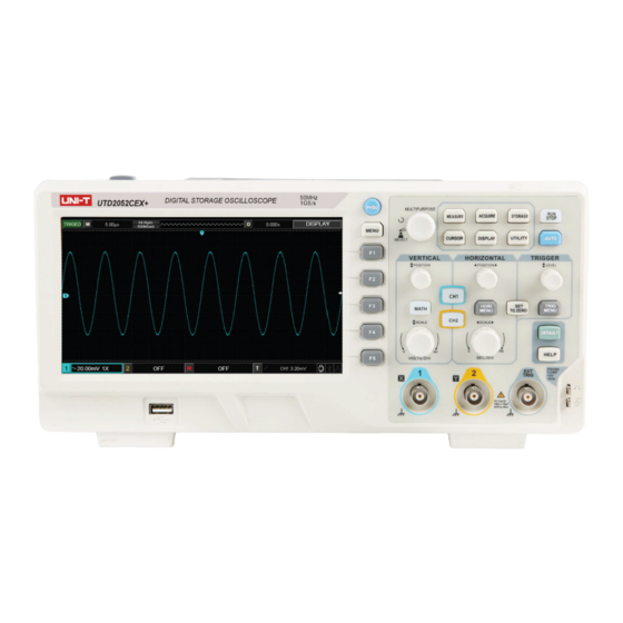
- Page 1 UTD2000 Series Digital Oscilloscope User Manual www.uni-trend.com.cn...
- Page 2 Preface Dear custumer, Thank you for choosing this UNI-T device. In order to safely and correctly use this instrument .please read this manual thoroughly, especially the Safety Notes part. After reading this manual, it is recommended to keep the manual at an easily accessible place, preferably close to the device, for future reference.
- Page 3 The probe, other accessories and fuses are not covered by warranty. If any genuine defect is found during the valid warranty period, Uni-T has the option to repair the defective product without any charge for parts or labor, or replace it with another product (at the discretion of Uni-T).
- Page 4 Avoid fire and personal injury: Use the correct power line: Only use the dedicated UNI-T power supply appointed to the local region or country for this product. The rating shall not be lower than the rating requirements. Mains supply cord set specification...
- Page 5 UTD2000 Series User Manual Do not operate the product if you suspect it is faulty, and please contact UNI-T authorized service personnel for inspection. Any maintenance, adjustment, or replacement of parts must be performed by UNI-T authorized maintenance personnel.
- Page 6 UTD2000 Series User Manual Safety Terms and Symbols The following terms may appear in this manual: Warning: The conditions and behaviors may endanger life. Note: The conditions and behaviors may cause damage to the product and other properties. The following terms may appear on the product: Danger: Performing this operation may cause immediate damage to the operator.
- Page 7 UTD2000 Series User Manual Preface The Manual introduces information related to operation of digital storage oscilloscope of UTD2000 series user manual. The Manual comprises the following chapters: Chapter 1 Introduction Guide Chapter 2 Vertical channel setting Chapter 3 Horizontal system setting Chapter 4 Trigger system setting Chapter 5 Sampling system setting Chapter 6 Display system setting...
- Page 8 UTD2000 Series User Manual Apart from easy to use, UTD2000 series DSO also has high performance indexes and powerful functions required for faster completion of measurement tasks. User can observe faster signals on UTD200 series DSO by high-speed real time sampling and equivalent sampling.
- Page 9 UTD2000 Series User Manual Contents Guaranty and Declaration ....................2 General Safety Overview ....................4 Safety Terms and Symbols ....................6 Preface..........................7 Contents ..........................9 Chapter I Introductions ....................11 1.1 General Inspection ..................... 11 1.2 Function Inspection .................... 11 1.3 Front and Rear Panel ..................
- Page 10 UTD2000 Series User Manual 7.2 Voltage Parameter ..................... 38 7.3 Time parameter ....................39 Chapter VIII Cursor Measurement ................41 Chapter IX Storage and Load System ................41 9.1 Setup storage and load ..................43 9.2 Waveform storage and load ................44 9.3 Bit map storage and load ...................
- Page 11 In case of damages to the appearance of instrument, abnormal operation or failure to pass the performance tests, please contact the UNI-T product distributors or local UNI-T offices. If the instrument is damaged due to transportation, please pay attention to keeping the package, notify transportation department and UNI-T product distributors and UNI-T will make arrangement for repair or replacement.
- Page 12 UTD2000 Series User Manual frequency defaults at 1kHz. Probe Compensation Siganl Tip Ground Terminal (4) Function Check Press AUTO (auto setting) button, square wave appears on the display screen, the wave range is about 3Vpp and the frequency is 1kHz. Go back to step 3 and check other channels in a same way.
- Page 13 UTD2000 Series User Manual Warning: In order to avoid electric shock when measuring high voltage with probe, please ensure that the insulation lead of the probe is in good condition and do not contact the metal part of the probe when connecting high pressure power supply. 1.3 Front and Rear Panel Control Menu button Function menu button...
- Page 14 UTD2000 Series User Manual 1.4 Display (1) Display description Horizontal trigger area Main time base setting Time of center scale line Trigger state display Soft button menu corresponds to different buttons Channel 1 mark Waveform display window Channel 2 mark Vertical scale coefficient of channel (2) Soft button Press any soft button to activate corresponding menu.
- Page 15 UTD2000 Series User Manual control area. Practices below will gradually guide you to get familiar with the controlling of the vertical system. Figure 1-6 Vertical Control Area on the Panel (1) Vertical POSITION: vertical position knob, user can change the current vertical position of channel waveform, the vertical position value will display on the baseline cursor area.
- Page 16 UTD2000 Series User Manual 1. Use horizontal SCALE knob to change gear position settings of horizontal time base and observe the changes of state information. Turn horizontal SCALE knob to change “SEC/DIV” time base gear position, and you can find that corresponding changes have taken place in the time base gear position display of corresponding channel in the status bar.
- Page 17 UTD2000 Series User Manual Chapter II Vertical System UTD2000 series DSO provides two analog input channels, each channel has an independent vertical menu. Each channel for UTD2000 series DSO can be set independently through the vertical system menu. After pressing CH1 or CH2 function key, the system shall display function menu of CH1 or CH2 channel.
- Page 18 UTD2000 Series User Manual Figure 2-1 Blocked DC Component of Signal Press F1 to select as DC coupling, you should be able to see both the DC and AC components of measured signals at CH1 channel as shown in figure below. Figure 2-2 Simultaneous Display of Signal DC and AC Components If you Press F1 to select as GND, to set CH1 to connect to the internal ground of the instrument, both DC and AC components of the input signal are blocked.
- Page 19 UTD2000 Series User Manual Figure 2-4 Waveform Display When Setting Bandwidth Limit as OFF Press F2 to set the BW Limit as 20MHz, the noises or high-frequency component over 20MHz in measured signal shall be attenuated, waveform display shown in figure below. BW Limit Mark Figure 2-5 Waveform Display When Setting Bandwidth throttling as ON 2.3 Setting probe Rate...
- Page 20 UTD2000 Series User Manual 2.4 Vertical Volts/Div adjustment setting Adjustments of vertical deflection factor V/div gear position can be set to coarse adjustment and fine adjustment. For coarse adjustment, V/div can be adjusted in step of multiple of 1, 2 and 5, the V/div range is 1mV/div~20V/div.
- Page 21 UTD2000 Series User Manual Figure 2-9 Vertical Channel Inverted Settings (Invert: ON) 2.6 Unit Press Unit to set the unit as “V” or “A”, the default unit is V. After the unit is set, the unit on channel status tag will change accordingly. 2.7 Mathematical operation function Display results of CH1 &...
- Page 22 UTD2000 Series User Manual 2.8 FFT spectral analysis Enter FFT (fast fourier transform) operation, the time domain (YT) signal can be converted into frequency domain signal. At FFT operation, it is convenient to observe signals of the following types: ● Measure harmonic content and distortion in the system ●...
- Page 23 UTD2000 Series User Manual The frequency resolution of Hamming Signal levels, before and after transient state or Hamming window is slightly superior to Hanning short pulse, are of large difference. window. The best amplitude resolution and the worst Mainly used for single frequency signal seeking Blackman frequency resolution.
- Page 24 UTD2000 Series User Manual Chapter III Horizontal System 3.1 Horizontal control (1) Horizontal control knob Change the horizontal time-base scale through SCALE knob, changing of horizontal scale can lead to expansion or shrink of waveforms relative to screen center. The horizontal system can be controlled by the following panel buttons/knobs.
- Page 25 UTD2000 Series User Manual 3.3 Window extension Extension window is used to enlarge the waveform so that users view the image details. The setting of window extension shall not be slower than that of main time base. Waveform horizontal extension part Extensive time base Main time base Waveform horizontal extension part...
- Page 26 UTD2000 Series User Manual According to sin θ=A/B or C/D, θ is the angle difference of channels, the definition of A, B, C, D is shown in figure above, so the angle difference is: θ=±arcsin (A/B) or θ=±arcsin (C/D). If the elliptical axis lies on I, III quadrant, then the phase difference of angle should lie on I, IV quadrant, that is within (0~π/2) or (3π/2~2π).
- Page 27 UTD2000 Series User Manual Chapter IV Trigger System When to collect data and display waveform depends on the trigger system. The DSO will convert the unstable displays into meaningful waveform after the trigger is set correctly. When the DSO start collecting data, it will firstly collect enough data to draw a waveform on the left of trigger.
- Page 28 UTD2000 Series User Manual Set to automatic trigger. The DSO will continuously perform data acquisition AUTO without triggering signal. Set to normal trigger. The DSO will only perform data acquisition when there is Mode Normal triggering signal. Set to single trigger. The DSO will only perform 1 cycle of the data acquisition Single when there is triggering signal.
- Page 29 UTD2000 Series User Manual Table 4-3 Pulse width setting menu Function Menu Setting Description Positive Set the positive pulse width as trigger signal Polarity Negative Set the negative pulse width as trigger signal > Trigger when pulse width is greater than the set value Pulse width <...
- Page 30 UTD2000 Series User Manual The DSO generates a trigger when the slew rate of rising edge of signal is Rising < lower than the specified slew rate. The DSO generates a trigger when the slew rate of rising edge of signal is Rising <>...
- Page 31 UTD2000 Series User Manual NTSC Applicable NTSC video signal. All line Set the video line to synchronous triggering. Set the video to sync and trigger on specific line, adjust through the Line multifunctional knob on front panel. Sync Odd field Set the video to sync and trigger on odd field.
- Page 32 UTD2000 Series User Manual Figure 4-3 Observing Signals with Two Different Frequencies by Alternating Trigger Mode Table 4-7 Alternating Trigger Menu (Page 1) Function Setting Description Menu Type Alternating Select CH1 as current channel Channel selection Select CH2 as current channel Edge Set the edge as trigger mode Trigger mode...
- Page 33 UTD2000 Series User Manual 4.6 Trigger Holdoff Trigger holdoff time adjustment is used to observe complex waveform (pulse string series). Holdoff time refers to the waiting time for the DSO to restart trigger circuit. During holdoff time, the DSO will not trigger until the holdoff time is over. Table 4-9 Trigger Holdoff Menu Function Menu Setting...
- Page 34 UTD2000 Series User Manual ■ External trigger: This type of trigger source can be used not only in collecting data in two channels but also in triggering the third channel at the same time. For example, the external clock or the signal from circuit to be measured can be served as trigger source. EXT trigger source use the external trigger signal connected to EXT TRIG junction.
- Page 35 UTD2000 Series User Manual Chapter V Acquire System As shown in the figure below, the ACQUIRE on the control area is the function button of Acquire System. Figure 5-1 Function Key of Acquire System Press ACQUIRE button to enter data acquisition setting menu, set the data acquisition mode through menu control button.
- Page 36 UTD2000 Series User Manual Notice: (1) Please select real-time sampling mode when observing single signal. (2) Please select equivalent sampling mode when observing high frequency periodic signal. (3) Please select peak detection mode when hoping to observe the signal envelope for any modulation signal.
- Page 37 UTD2000 Series User Manual Chapter VI Display System As shown in the figure below, the DISPLAY on the control area is the function button of Display System. Figure 6-1 Function Keys of Display System Press DISPLAY button to enter display setting menu as shown in the table below. Table 6-1 Display Menu (Page 1) Function Setting...
- Page 38 UTD2000 Series User Manual Chapter VII Automatic Measurement UTD2000 series DSO support up to 34 types of waveform measurement parameters. Figure 7-1 Function Key of Auto Measurement 7.1 Measurement Menu Press MEASURE to enter Measurement menu. Table 7-1 Automatic measurement menu (Page 1) Function Menu Setting Description...
- Page 39 UTD2000 Series User Manual Figure 7-2 Voltage Parameter Diagram Voltage parameters of UTD2000 series DSO include: Max value (Max): The voltage value from waveform highest level to GND. Min value (Min): The voltage value from waveform lowest level to GND. Top value (High): The voltage value from waveform flat top to GND.
- Page 40 UTD2000 Series User Manual Frequency (Freq): The reciprocal of the period Rise time (Rise): The time for waveform amplitude to rise from 10% to 90%. Fall time (Fall): The time for waveform amplitude to fall from 90% to 10%. Rise delay: The time for main source and slave source to delay between two rising edges Fall delay: The time for main source and slave source to delay between two falling edges.
- Page 41 UTD2000 Series User Manual Chapter VIII Cursor Measurement Use CURSOR to measure waveform X axis (time) and Y axis (voltage). Press CURSOR to enter cursor measurement menu. Figure 8-1 Function Key of CURSOR 8.1 Cursor measurement menu Press CURSOR to enter cursor measurement menu. Table 8-1 cursor measurement menu Function menu Setting...
- Page 42 UTD2000 Series User Manual Figure 8-2 Cursor measurement for time X time: Rotate Multipurpose knob to adjust the position of AX, press Multipurpose knob to adjust BX, shit between BX and AX with same way. A/B represents the time distance between zero point and the cursor A/B. B-A represents the difference beween cursor A and cursor B.
- Page 43 UTD2000 Series User Manual Chapter IX Storage The DSO setting, waveform and screen image can be store in DSO or USB, the stored setting or waveform can be recalled when needed. Press STORAGE to enter storage setting interface. Figure 9-1 Function Key of STORAGE 9.1 Set storage and load Press the Storage button, then Press F1 to choose storage type Setup, and you will see the following menu.
- Page 44 UTD2000 Series User Manual 9.2 Waveform storage and load Press the Storage button, then press F1 to choose storege type as Reference Waveform, and you will see the following menu. Table 9-2 Reference waveform menu (Page 1) Function Menu Setting Description Reference Type...
- Page 45 UTD2000 Series User Manual 9.3 Bit map storage and load Press the Storage button, then press F1 to choose storege type Data File, and you will see the following menu. Table 9-6 Interface storage menu Function Menu Setting Description Type Data file The selected storage type is data file, stored in CSV format.
- Page 46 UTD2000 Series User Manual Chapter X Utility System Press UTILITY to enter utility menu. Figure 10-1 Function Key of UTILITY Table 10-1 Utility menu (Page 1) Function menu Setting Description System Config See chart Enter system setup menu, the operation option include self-clibration, 10-3 system information and clear information.
- Page 47 UTD2000 Series User Manual 10.1 Pass/Fail Pass/Fail test: Detect whether or not the input signal is in the specified scope of template. If the input signal is within the scope, it is PASS, while if the input signal is out of the scope, it is FAIL.
- Page 48 UTD2000 Series User Manual Vertical 1~255 Set vertical tolerance of template through multifunctional knob. tolerance Back Return to previous menu (Pass/Fail Test Menu). (8) Start the test, press F1 to conduct Pass/Fail test. 10.2 Recorder Record the current waveform frame by frame through waveform recording function. Table 10-6 Waveform Recording Menu Function Setting...
- Page 49 UTD2000 Series User Manual Table 10-7 AUTO strategy menu Function Menu Setting Description Channel setup Release/Lock Release: The channel setting is set as default after AUTO operation. Lock: The channel setting is unchanged after AUTO operation. Sampling setup Release/Lock Release: The acquiring mode automatically changes to normal sampling after AUTO operation.
- Page 50 UTD2000 Series User Manual Chapter XI Other funtion botton 11.1 AUTO Setting Based on input signals, Auto Setting selects appropriate time-based scale, Volt/Divs, trigger based to display waveform on the screen automatically. Press AUTO to enter automatic setting. AUTO Setting is only applicable to conditions below: 1) AUTO Setting is only applicable to signals with simple and single frequency.
- Page 51 UTD2000 Series User Manual 11.3 Help Menu Press the HELP key to go into help menu, then press any key will display the help information of this key. 11.4 Upgrade program The USB upgrade program makes upgrade easier and more flexible. To use this function, please follow the steps below: (1) Download a program file to be updated from internet and store the file in USB.
- Page 52 UTD2000 Series User Manual Chapter XII Applicaion example Example 1: Measuring simple signals To observe and measure an unknown circuit signal, and to quickly display and measure the signal's frequency and peak-to-peak value. (1) To quickly display this signal, follow the steps below: ①...
- Page 53 UTD2000 Series User Manual (1) To display CH1 and CH2 signals ① Press AUTO. ② Continue to adjust the horizontal and vertical range until you get the desired waveform display. ③ Press CH1 to select CH1. Adjust vertical position of the CH1 waveform by turning the vertical position control knob.
- Page 54 UTD2000 Series User Manual ① Press TRIG MENU in the trigger control zone to display the trigger setup menu. ② In this menu, use F1~F5 set the trigger type to EDGE, set trigger source to CH1, set inclination to Rising, set trigger type to Single and set trigger coupling to AC. ③...
- Page 55 UTD2000 Series User Manual (2) Connect the signal to ensure stable display of waveform. (3) Improving trigger by setting trigger coupling. ① Press TRIG MENU in the trigger zone to display the trigger setup menu. ② Set trigger coupling to Low Frequency Holdoff or High Frequency Holdoff. Low frequency holdoff is seting up a high-pass filter.
- Page 56 UTD2000 Series User Manual Measuring one step voltage of the step signal To measure one step voltage of the step signal, follow the steps below: 1. Press CURSOR to display the cursor measurement menu. 2. Press menu operation key F1 to set cursor type to VOLTAGE. 3.
- Page 57 UTD2000 Series User Manual Chapter XIII System Prompts and Trouble- shooting 13.1 Definitions of System Prompts Adjustment at Ultimate Limit: This informs you that the multifunction control knob has reached its adjustment limit in the current status. No further adjustment is possible. When the vertical deflection factor switch, time base switch, X shift, vertical shift and trigger level adjustments have reached their ultimate limits, this prompt will appear.
- Page 58 UTD2000 Series User Manual or to filter any high or low frequency noise that is interfering with triggering. (4) Slow refresh ①. Check if the acquiring mode in ACQUIRE button menu is average, and the average times are large. ②. If increasing the refresh speed is needed, please decrease the average times appropriately or select other acquiring modes, i.e.
- Page 59 UTD2000 Series User Manual Chapter XIV Technical Information Except for those specifications marked with “Typical”, all specifications have warranties. Unless otherwise specified, all technical specifications are applicable to the probes with attenuation switch set as 10× as well as UTD2000 series DSO. DSO must first meet the following two conditions to meet those specification standards: ...
- Page 60 UTD2000 Series User Manual Time-base accuracy ≤(50+2×Service life)ppm Record length 2×512k sampling point Storage depth Single channel: 64k;Double channel: 32k Sampling rate and delay ±50ppm (any time interval ≥1ms ) time accuracy Measurement accuracy of Single time: ± (1 sampling time interval+50ppm×reading+0.6ns) >16 average values: ±...
- Page 61 UTD2000 Series User Manual time ≥20ns Pre-trigger capacity Normal mode/scan mode, pre-trigger/delay trigger, the pre-trigger depth is adjustable. Hold-off range 80ns~1.5s Set the level to 50% Operate under the condition of input signal frequency of ≥50Hz (Typical) Trigger mode AUTO, normal, single High-frequency holdoff Hold off signals over 80kHz Low-frequency holdoff...
- Page 62 UTD2000 Series User Manual Measurement scope Screen or cursor Measurement statistics Average value, maximum value, minimum value and standard deviation. Math Math operation +, -, ×, ÷ Window Rectangle, Hanning、Blackman、Hamming Vertical scale Vrms、dBVrms Digital filtering Low pass, high pass, band pass, band reject Storage Setting Internal: 20 groups.
- Page 63 UTD2000 Series User Manual Frequency (Typical) 10Hz,100Hz, 1kHz(Default), 10kHz Power Source Power voltage 100V-240V~(Fluctuations±10% ),50/60Hz Power consumption 100VA max Fuse F 1.6A, 250V Environment Specifications Intended use Indoor use Pollution degree Operating temperature Operating Temperature Range: 0℃~+40℃ Storage Temperature Storage Temperature Range: -20℃~+60℃ Cooling Build-in cooling fan <35℃: ≤90%RH...
- Page 64 If any such product proves defective during this warranty period, UNI-T will repair the defective product or provide a...
- Page 65 UNI-T sales and maintenance office. Save and except the guarantee given herein or in other applicable warranty, UNI-T makes no other express or implied guarantee, including but not limited to any implied guarantee on the product's tradability and suitability for any specific purpose.
- Page 66 UTD2000 Series User Manual...