Table of Contents
Advertisement
ANSI Z359.14 Class B
ANSI A10.32
A
D
W
L
WR
B
D
W
L
WR
1
OSHA 1910.140
OSHA 1926.502
1
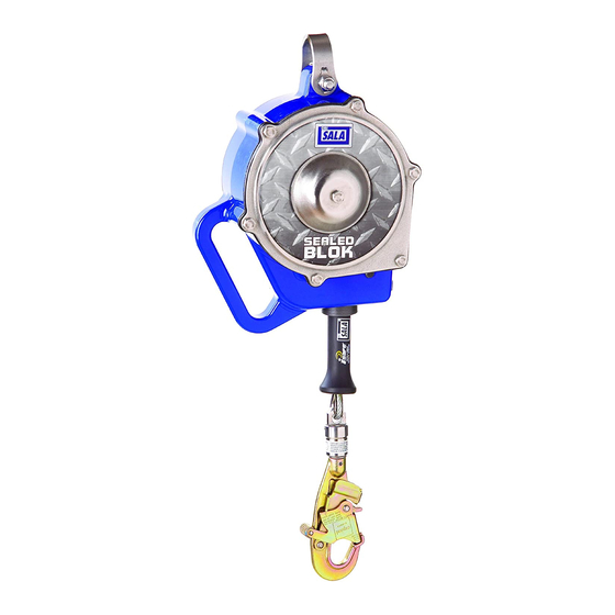
Sealed-Blok™
Cable
A
3400800
9501479
A
3400801
9501613
A
3400802
9501613
A
3400807
9501613
A
3400825
9501479
A
3400826
9501613
A
3400827
9501613
A
3400833
9501613
A
3400849
9501613
A
3400850
9501479
A
3400851
9501613
A
3400852
9501613
A
3400853
9501479
A
3400857
9501613
B
3400858
9501613
Sealed-Blok™
SeLf-RetRACtINg DevICeS
USER INSTRUCTIONS
5903887 R
Retrieval
WR
L
30 ft
10.2 in
(9.0 m)
(25 cm)
30 ft
10.2 in
(9.0 m)
(25 cm)
30 ft
10.2 in
(9.0 m)
(25 cm)
30 ft
10.2 in
(9.0 m)
(25 cm)
15 ft
10.2 in
(4.5 m)
(25 cm)
15 ft
10.2 in
(4.5 m)
(25 cm)
15 ft
10.2 in
(4.5 m)
(25 cm)
15 ft
10.2 in
(4.5 m)
(25 cm)
15 ft
10.2 in
ü
(4.5 m)
(25 cm)
30 ft
11.5 in
ü
(9 m)
(29 cm)
30 ft
11.5 in
ü
(9 m)
(29 cm)
30 ft
11.5 in
ü
(9 m)
(29 cm)
30 ft
11.5 in
ü
(9 m)
(29 cm)
30 ft
11.5 in
ü
(9 m)
(29 cm)
30 ft
11.5 in
ü
(9 m)
(29 cm)
2
. E
ev
W
D
7.6 in
4.3 in
420 lbs
(19 cm)
(11 cm)
(189 kg)
7.6 in
4.3 in
420 lbs
(19 cm)
(11 cm)
(189 kg)
7.6 in
4.3 in
420 lbs
(19 cm)
(11 cm)
(189 kg)
7.6 in
4.3 in
420 lbs
(19 cm)
(11 cm)
(189 kg)
7.6 in
4.3 in
420 lbs
(19 cm)
(11 cm)
(189 kg)
7.6 in
4.3 in
420 lbs
(19 cm)
(11 cm)
(189 kg)
7.6 in
4.3 in
420 lbs
(19 cm)
(11 cm)
(189 kg)
7.6 in
4.3 in
420 lbs
(19 cm)
(11 cm)
(189 kg)
7.6 in
4.3 in
420 lbs
(19 cm)
(11 cm)
(189 kg)
9.4 in
5.4 in
420 lbs
(24 cm)
(14 cm)
(189 kg)
9.4 in
5.4 in
420 lbs
(24 cm)
(14 cm)
(189 kg)
9.4 in
5.4 in
420 lbs
(24 cm)
(14 cm)
(189 kg)
9.4 in
5.4 in
420 lbs
(24 cm)
(14 cm)
(189 kg)
9.4 in
5.4 in
420 lbs
(24 cm)
(14 cm)
(189 kg)
9.4 in
5.4 in
420 lbs
(24 cm)
(14 cm)
(189 kg)
© 3M 2020
Advertisement
Table of Contents

Related Manuals for 3M DBI-SALA Sealed-Blok 3400800


Summary of Contents for 3M DBI-SALA Sealed-Blok 3400800
- Page 1 420 lbs ü 3400857 9501613 (9 m) (29 cm) (24 cm) (14 cm) (189 kg) 30 ft 11.5 in 9.4 in 5.4 in 420 lbs ü 3400858 9501613 (9 m) (29 cm) (24 cm) (14 cm) (189 kg) © 3M 2020...
- Page 2 FC = FF+DD+SF...
- Page 3 ft (m) (0.0) (0.6) (1.2) (1.8) (2.4) (3.0) (3.7) (4.3) (4.9) (5.5) (6.1) û û û û û û û û û (2.6) (0.0) û û û û û û (2.1) (2.3) (2.6) (2.9) û û û û (6.1) (2.1) (2.3) (2.5) (2.7)
- Page 5 ü û...
- Page 6 WARNING 9502313 Rev. D 30’ (9 m) SRDs only.
-
Page 7: Safety Information
Ensure there is adequate fall clearance when working at height. Never modify or alter your fall protection equipment. Only 3M or parties authorized in writing by 3M may make repairs to the equipment. Prior to use of fall protection equipment, ensure a rescue plan is in place which allows for prompt rescue if a fall incident occurs. - Page 8 Before using this equipment, record the product identification information from the ID label in the ‘Inspection and Maintenance Log’ at the back of this manual. Always ensure you are using the latest revision of your 3M instruction manual. Visit the 3m website or contact 3M Technical Services for updated instruction manuals.
- Page 9 Do not work above the level of your anchorage. • Do not lengthen SRDs by connecting a lanyard or similar component without consulting 3M. For product-specific information relating to free fall and fall clearance values, please refer to Table 1 of this instruction.
- Page 10 Do not use equipment that is not compatible. Ensure all connectors are fully closed and locked. 3M connectors (snap hooks and carabiners) are designed to be used only as specified in each product’s user’s instructions. See Figure 6 for examples of inappropriate connections. Do not connect snap hooks and carabiners: To a D-ring to which another connector is attached.
-
Page 11: Installation
3.0 Installation PLANNING: Plan your fall protection system before starting your work. Account for all factors that may affect your safety before, during, and after a fall. Consider all requirements and limitations defined in this manual. ANCHORAGE: Figure 7 illustrates typical SRD anchorage connections. The anchorage (A) should be directly overhead to minimize Free Fall and Swing Fall hazards (see Section 2). -
Page 12: Maintenance, Service, And Storage
(A) can be used in conjunction with the handheld reading device and web based portal to simplify inspection and inventory control and provide records for your fall protection equipment. For details, contact a 3M Customer Service representative (see back cover). Follow the instructions provided with your handheld reader, or on the web portal, to transfer your data to your web log. - Page 13 7.0 Labels Figure 17 illustrates labels on the the Ultra-Lok SRDs and their locations. All labels must be present on the SRD. Labels must be replaced if they are not fully legible. Information provided on each label is as follows: Length of Lifeline (Maximum Lifting Distance) This product is Radio Frequency Identification (RFID) enabled and contains an electronic tag that can be read by compatible readers - providing inspection logs, inventory management, and other safety information.
- Page 14 Table 3 – Inspection & Maintenance Log Serial Number(s): Date Purchased: Model Number: Date of First Use: Inspected By: Inspection Date: Before Competent Each Use Person Component: Inspection: Inspect for loose bolts and bent or damaged parts. (Figure 12) Inspect Housing (A) for distortion, cracks, or other damage. Inspect the Swivel Eye (B) for distortion, cracks, or other damage.
-
Page 15: Eu Declaration Of Conformity
LIMITED REMEDY: Upon written notice to 3M, 3M will repair or replace any product determined by 3M to have a factory defect in workmanship or materials. 3M reserves the right to require product be returned to its facility for evaluation of warranty claims. This warranty does not cover product damage due to wear, abuse, misuse, damage in transit, failure to maintain the product or other damage beyond 3M’s control.