Fluke III Series Instruction Sheet
Hide thumbs
Also See for III Series:
- Instruction sheet (13 pages) ,
- Instruction sheet (13 pages) ,
- Instruction sheet (13 pages)
Table of Contents
Advertisement
Quick Links
W Read First: Safety Information
•
Never use the meter if the meter or test leads look damaged.
•
Be sure the test leads and switch are in the correct position
for the desired measurement.
•
Never measure resistance in a circuit when power is applied.
•
Never touch the probe to a voltage source when the test
leads are plugged into the 10 A or 40 mA input jack.
•
Never apply more than rated voltage between any input jack
and earth ground.
•
Be careful when working with voltages above 60 V dc or 30
V ac rms. Such voltages pose a shock hazard.
•
Keep your fingers behind the finger guards on the test
probes when making measurements.
To avoid false readings, which could lead to
possible electric shock or personal injury, replace
the battery as soon as the battery indicator M
appears.
Symbols
W
Read First: Safety Information
Y
Dangerous Voltage May Be Present
T
Double Insulation
Overvoltage Installation Category per IEC 1010:
CAT II
Typical locations include main wall outlets, local
appliances, and portable equipment.
CAT III
Typical locations include switches in the fixed
installation and equipment for industrial use
permanently connected to the fixed installation.
PN 687589 August 1997 Rev. 2, 4/98
© 1997, 1998 Fluke Corporation. All rights reserved. Printed in U.S.A.
All product names are trademarks of their respective companies.
Series III Multimeter
W
Warning
79/26
Instruction Sheet
®
Advertisement
Table of Contents

Related Manuals for Fluke III Series


Summary of Contents for Fluke III Series
- Page 1 Typical locations include switches in the fixed installation and equipment for industrial use permanently connected to the fixed installation. PN 687589 August 1997 Rev. 2, 4/98 © 1997, 1998 Fluke Corporation. All rights reserved. Printed in U.S.A. All product names are trademarks of their respective companies.
-
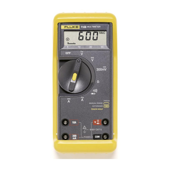
Page 2: Input Jacks
Input Jacks Milliamp Volts, Ohms, Diode Test 600V Common Terminal 1000V FUSED jo1f.eps See Specifications for overload protection. Ranging The meter defaults to autorange when you turn on the meter. Manual ranging is available in V ac, V dc, Hz, ohms, capacitance, A ac, and A dc. - Page 3 Automatic Touch Hold Mode ® W Warning To avoid electric shock, do not use the Touch ® Hold mode to determine if a circuit with high ® voltage is dead. The Touch Hold mode will not capture unstable or noisy readings. ®...
-
Page 4: Frequency (Hz)
Standby If the meter is on but is inactive for an hour (20 minutes in diode test), the screen only displays four bar graph segments. To resume operation, turn the rotary switch or press a button. AC and DC Voltage (K L m L) Volts AC Volts DC Millivolts DC... -
Page 5: Diode Test (G)
Resistance (e) Turn off the power and discharge all capacitors. An external voltage across a component will give invalid resistance readings. RANGE jo7f.eps Diode Test (G) Good Diode Good Diode RANGE RANGE Single Beep Reverse Bias Forward Bias Bad Diode Bad Diode RANGE RANGE... -
Page 6: Lead Resistance Compensation
Lead Resistance Compensation This function compensates for resistance in the leads and the meter’s internal protection circuitry. You can compensate in either Lo-Ohms or continuity. RANGE RANGE RANGE RANGE 1 second jo17f.eps When zero is displayed, compensation has occurred. The meter stays compensated until you change functions. - Page 7 Continuity Test ( R ) RANGE RANGE jo8f.eps Opens or shorts > 1 ms are detected. Press momentarily for lead compensation. Press 1 second to turn the beeper off and place the meter into Lo-Ohms autoranging. Capacitance (E) Turn off the power and discharge the capacitor. If the capacitor requires more discharging, diSC displays while the capacitor discharges.
-
Page 8: Probe Holder
Turn off power to the circuit. Break the circuit. (For circuits of more than 10 amps, use a current clamp.) Put the meter in series with the circuit as shown and turn power on. RANGE jo10f.eps Probe Holder jo21f.eps Maintenance Warning To avoid electric shock, remove the test leads before opening the case, and close the case before... -
Page 9: Battery And Fuse Replacement
To clean the meter, use a damp cloth and mild detergent; do not use abrasives or solvents on the meter. Service and Parts To contact Fluke, call one of the following telephone numbers: USA and Canada: 1-888-99-FLUKE (1-888-993-5853) Europe: +31 402-678-200... -
Page 10: Specification
Specification 1 year, 18°C to 28°C (64°F to 82°F) Accuracy specifications: ≤ 90% RH ±([% of reading] + [number of least significant digits]) Display Digital: 4000 counts, updates 4/sec Analog: 63 segments, updates 40/sec Frequency: 9,999 counts Capacitance: 9,999 counts Response Time of Digital V ac <... - Page 11 AC readings are ac-coupled, true rms, and are valid from 5% to 100% of range for CF 1.4. For crest factors other than 1.4, add ±(2% or reading + 2% of range). Maximum CF is 3 at full scale, 6 at half scale.
- Page 12 Function Range Accuracy ±(0.01%+1) Frequency* 99.99, 999.9, 9.999 kHz, 20.00 kHz *For rectangular waveforms 25% ≤ duty cycle ≤ 75%, V ac ≤ 1 kHz Frequency Counter Sensitivity Input Range* Minimum Sensitivity (RMS Sine Wave) 500 Hz to 20 kHz 1.0 Hz to 500 Hz** 4 V ac 0.3 V...