Table of Contents
Advertisement
SERVICE MANUAL
Ver 1.0 2004.03
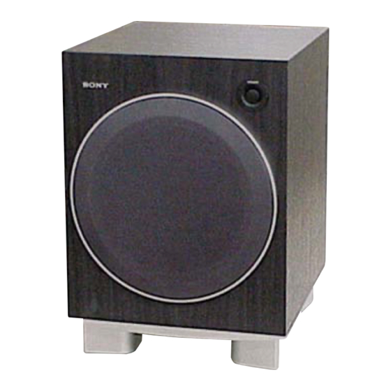
• SA-WMS367 is the subwoofer
section in SA-VE367T.
For the US model
AUDIO POWER SPECIFICATIONS
POWER OUTPUT AND TOTAL HARMONIC
DISTORTION:
with 6 ohm loads, from 20 - 200 Hz; rated 120 watts per
channel minimum RMS power, with no more than 10%
total harmonic distortion from 250 milliwatts to rated
output.
Speaker system
Active subwoofer,
magnetically shielded
Speaker unit
Woofer: 20 cm (8 in.)
Enclosure type
Acoustically loaded
Bass Reflex
Reproduction frequency range
26 Hz - 200 Hz
Continuous RMS power output
135 W (6 ohms, 100 Hz,
10% THD)
Sony Corporation
9-877-698-01
2004C04-1
Home Audio Company
© 2004.03
Published by Sony Engineering Corporation
SA-WMS367
SPECIFICATIONS
Inputs
INPUT (input pin jack)
SPEAKER IN (input terminals)
Outputs
SPEAKER OUT (output terminals)
General
Power requirements
Power consumptions
Dimensions (w/h/d)
Mass
Design and specifications are subject to change without
notice.
US Model
Canadian Model
120 V AC, 60 Hz
130 W
1 W (standby mode)
Approx. 290 × 400 × 424 mm
(11
× 15
× 16
in.)
1/8
1/4
3/8
Approx. 13 kg
(28 lb 11 oz)
SUBWOOFER
1
Advertisement
Table of Contents

Summary of Contents for Sony SA-WMS367
- Page 1 SA-WMS367 SERVICE MANUAL US Model Canadian Model Ver 1.0 2004.03 • SA-WMS367 is the subwoofer section in SA-VE367T. SPECIFICATIONS For the US model Inputs INPUT (input pin jack) AUDIO POWER SPECIFICATIONS SPEAKER IN (input terminals) POWER OUTPUT AND TOTAL HARMONIC...
-
Page 2: Table Of Contents
CRITIQUES POUR LA SÉCURITÉ DE FONCTIONNEMENT. NE REPLACE THESE COMPONENTS WITH SONY PARTS WHOSE REMPLACER CES COMPOSANTS QUE PAR DES PIÈCES SONY PART NUMBERS APPEAR AS SHOWN IN THIS MANUAL OR DONT LES NUMÉROS SONT DONNÉS DANS CE MANUEL OU IN SUPPLEMENTS PUBLISHED BY SONY. -
Page 3: General
Do not use any type of abrasive pad, scouring powder or solvent such as alcohol or benzine. If you have any questions or problems concerning your speaker system, please consult your nearest Sony dealer. -
Page 4: Printed Wiring Boards - Main Section
SA-WMS367 2-3. PRINTED WIRING BOARDS — MAIN SECTION — • Refer to page 3 for Circuit Boards Location. : Uses unleaded solder. (Page 6) T102 CN702 CN701 C706 JW704 C711 BC903 D701 C709 T202 D702 R714 JW703 C704 R708 R702... -
Page 5: Schematic Diagram - Main Section
SA-WMS367 2-4. SCHEMATIC DIAGRAM — MAIN SECTION — • Refer to page 8 for IC Block Diagram. Q535 R540 D533 D532 R532 R535 S201 BC803 BC203 CN804 D203 R533 Q532 R538 C201 Q534 IC530(2/2) R541 C531 D531 BC202 R537 R542... -
Page 6: Printed Wiring Boards - Control Section
SA-WMS367 2-5. PRINTED WIRING BOARDS — CONTROL SECTION — • Refer to page 3 for Circuit Boards Location. : Uses unleaded solder. (Page 4) (Page 4) • Semiconductor Location Ref. No. Location D501 C-12 D502 C-12 D503 C-12 D504 C-12... -
Page 7: Schematic Diagram - Control Section
SA-WMS367 2-6. SCHEMATIC DIAGRAM — CONTROL SECTION — TM501 IC501(1/2) R501 R505 C502 R502 R510 C503 R504 R506 R511 IC501(2/2) R503 C504 C501 R513 R514 R507 R508 R509 R512 C505 BC601 R604 R605 IC604(2/2) IC601(1/2) IC601(2/2) IC602(1/2) R606 C612 C613... -
Page 8: Ic Block Diagram
SA-WMS367 2-7. IC BLOCK DIAGRAM IC701 STK404-130S (POWER AMP Board) 11 12... -
Page 9: Exploded Views
SA-WMS367 SECTION 3 EXPLODED VIEWS NOTE: • The mechanical parts with no reference • Color Indication of Appearance Parts The components identified by mark 0 or dotted line with mark number in the exploded views are not supplied. Example : 0 are critical for safety. -
Page 10: Rear Section
SA-WMS367 3-2. REAR SECTION not supplied supplied with not supplied RV601, RV602 (TERMINAL board) T102 not supplied (CONTROL board) F901 not supplied not supplied (POWER SUPPLY board) not supplied not supplied (POWER AMP board) not supplied The components identified by Les composants identifiés par une... -
Page 11: Electrical Parts List
SA-WMS367 SECTION 4 CONTROL MAIN ELECTRICAL PARTS LIST NOTE: • Due to standardization, replacements in • Items marked “*” are not stocked since The components identified by mark 0 or dotted line with mark the parts list may be different from the they are seldom required for routine service. - Page 12 SA-WMS367 MAIN POWER AMP Ref. No. Part No. Description Remark Ref. No. Part No. Description Remark C304 1-104-666-11 ELECT 220uF < RESISTOR > C305 1-126-964-11 ELECT 10uF C306 1-126-964-11 ELECT 10uF R101 1-247-863-11 CARBON 1/4W C307 1-124-247-11 ELECT 10uF R102...
- Page 13 SA-WMS367 POWER AMP POWER SUPPLY POWER SWITCH TERMINAL Ref. No. Part No. Description Remark Ref. No. Part No. Description Remark < DIODE > POWER SWITCH BOARD ******************** D701 8-719-991-33 DIODE 1SS133T-77 D702 8-719-991-33 DIODE 1SS133T-77 < CONNECTOR > D703 8-719-991-33 DIODE 1SS133T-77 BC202 1-564-321-00 PIN, CONNECTOR (3.96mm PITCH) 2P...
- Page 14 SA-WMS367 Ref. No. Part No. Description Remark MISCELLANEOUS *************** 0 55 1-783-820-11 CORD, POWER 0 F901 1-532-745-11 FUSE, GLASS TUBE (3.15A/125V) SP401 1-825-151-21 SPEAKER (20cm) (WOOFER) 0 T102 1-443-275-11 TRANSFORMER, POWER The components identified by Les composants identifiés par une...
- Page 15 SA-WMS367 MEMO...
- Page 16 SA-WMS367 REVISION HISTORY Clicking the version allows you to jump to the revised page. Also, clicking the version at the upper on the revised page allows you to jump to the next revised page. Ver. Date Description of Revision 2004.03...


