3Com SuperStack 3 4950 Getting Started Manual
3com superstack 3 4950: quick start
Hide thumbs
Also See for SuperStack 3 4950:
- Datasheet (6 pages) ,
- Getting started manual (82 pages) ,
- Datasheet (4 pages)

Related Manuals for 3Com SuperStack 3 4950


Summary of Contents for 3Com SuperStack 3 4950
- Page 1 SuperStack Switch 4950 Getting Started Guide 3C17706 http://www.3com.com/ Part No. DUA1770-6AAA03 Published October 2001 ®...
- Page 2 All other company and product names may be trademarks of the respective companies with which they are associated. ENVIRONMENTAL STATEMENT It is the policy of 3Com Corporation to be environmentally-friendly in all operations. To uphold our policy, we are committed to: Establishing environmental performance standards that comply with national legislation and regulations.
-
Page 3: Table Of Contents
ONTENTS BOUT UIDE Conventions Related Documentation Accessing Online Documentation Product Registration Documentation Comments NTRODUCING THE UPER TACK WITCH About the Switch 4950 Summary of Hardware Features Summary of Software Features Switch 4950 — Front View Detail 10/100/1000BASE-T Ports 1000BASE-SX Ports GBIC Ports LEDs Switch 4950 —... - Page 4 The Power-up Sequence Powering-up the Switch 4950 Checking for Correct Operation of LEDs Connecting a Redundant Power System Choosing the Correct 10/100/1000BASE-T Cables Choosing the correct Fiber cables GBIC Operation Approved GBIC Transceivers Inserting a GBIC Transceiver ETTING P FOR Logging in as a Default User Changing Default Passwords Introduction to Setting Up...
- Page 5 PC-AT Serial Cable Modem Cable RJ-45 Pin Assignments ECHNICAL PECIFICATIONS ECHNICAL UPPORT Online Technical Services World Wide Web Site 3Com Knowledgebase Web Services 3Com FTP Site Support from Your Network Supplier Support from 3Com Returning Products for Repair NDEX EGULATORY OTICES...
-
Page 7: About This Guide
■ you detailed information on how to use the web interface and command line interface to manage the Switch. 3Com Network Supervisor - a powerful network management tool for ■ small to medium enterprise networks. A number of other useful applications. -
Page 8: Conventions
BOUT UIDE Conventions Table 1 Table 1 Notice Icons Table 2 Text Conventions Convention Screen displays Syntax Commands The words “enter” and “type” Keyboard key names Words in italics Table 2 list conventions that are used throughout this guide. Icon Notice Type Description Information note... -
Page 9: Related Documentation
Documentation accompanying the Advanced Redundant Power System. Documentation accompanying the Expansion Modules. Documentation accompanying 3Com Network Supervisor. This is supplied on the CD-ROM that accompanies the Switch. SuperStack 3 Switch Implementation Guide (PDF format) SuperStack 3 Switch Management Interface Reference Guide (HTML format). -
Page 10: Product Registration
3Com recommends that you copy the Docs/referenceguide directory as a whole to maintain the structure of the files. Product You can register your SuperStack 3 Switch on the 3Com Web site to Registration receive up-to-date information on your product: http://support.3com.com/registration/frontpg.pl Documentation Your suggestions are very important to us. -
Page 11: Introducing The Stack
NTRODUCING THE UPER This chapter contains introductory information about the SuperStack Switch 4950 and how it can be used in your network. It covers summaries of hardware and software features and also the following topics: About the Switch 4950 ■ Switch 4950 —... -
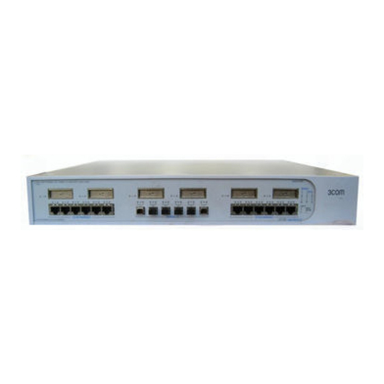
Page 12: About The Switch 4950
1: I HAPTER NTRODUCING THE About the Switch The Switch 4950 is a 10/100/1000 Mbps mixed media device which 4950 consists of: ■ ■ ■ Summary of Table 3 Hardware Features Switch 4950. Table 3 Hardware features 4950 UPER TACK WITCH 12 10/100/1000BASE-T ports 6 1000BASE-SX ports... -
Page 13: Summary Of Software Features
Summary of Software Table 4 Features Switch 4950. For information about using the software features of the Switch, refer to the “SuperStack 3 Switch Management Interface Reference Guide” on the CD-ROM that accompanies the Switch. Table 4 Software features Switch 4950 — Figure 1 Switch 4950 —... -
Page 14: 10/100/1000Base-T Ports
1: I 4950 HAPTER NTRODUCING THE UPER TACK WITCH 10/100/1000BASE-T The 12 10/100/1000BASE-T ports have RJ-45 connectors and are Ports configured as Auto MDIX (cross-over). The default state for these ports is auto-negotiation enabled, where the speed, duplex and flow control modes of a link are automatically detected to provide the highest available bandwidth with the link partner. -
Page 15: Leds
LEDs Table 5 lists LEDs visible on the front of the Switch, and how to read their status according to color. For information on using the LEDs for problem solving, see “Checking for Correct Operation of LEDs” Table 5 LED behavior Color Port Status LEDs Packet... -
Page 16: Switch 4950 - Rear View Detail
Indicates that Layer 3 is enabled on the Switch. Indicates that Layer 3 is disabled on the Switch. The 3Com product name of the Switch The 3Com 3C number of the Switch The unique MAC address (Ethernet address) of the Switch The serial number of the Switch “Connecting a... -
Page 17: Console Port
Console Port The console port allows you to connect a terminal and perform remote or local out-of-band management. The console port uses a standard null modem cable and is set to 19,200 kbps, 8 data bits, no parity and 1 stop bit. - Page 18 1: I 4950 HAPTER NTRODUCING THE UPER TACK WITCH...
-
Page 19: Installing The Switch
NSTALLING THE This chapter contains the information you need to install and set up the Switch 4950. It covers the following topics: Package Contents ■ Choosing a Suitable Site ■ Rack-mounting ■ Placing Units On Top of Each Other ■ The Power-up Sequence ■... -
Page 20: Package Contents
Water or moisture cannot enter the case of the Switch. Air temperature is not restricted around the Switch or through the vents in the side of the Switch. 3Com recommends that you provide a minimum of 25 mm (1 in.) clearance. -
Page 21: Rack-Mounting
If the Switch is installed in a 19-inch rack or closed assembly its local air temperature may be greater than room ambient temperature. ■ ■ ■ Rack-mounting The Switch is 1.5U and will fit in most standard 19-inch racks. However, as each Switch requires a shelf or runner to support its weight, you may need to allow a 2U space within the rack for each Switch. -
Page 22: Placing Units On Top Of Each Other
2: I HAPTER NSTALLING THE 4 Repeat steps 2 and 3 for the other side of the Switch. 5 Insert the Switch into the 19-inch rack and secure with suitable screws 6 Connect network cabling. Placing Units On Top of Each Other WITCH Figure 3 Fitting a bracket for rack-mounting You must use the screws supplied with the securing brackets. -
Page 23: The Power-Up Sequence
The Power-up The following sections describe how to get your Switch 4950 Sequence powered-up and ready for operation. Powering-up the Use the following sequence of steps to power-up the Switch. Switch 4950 1 Plug the power cord into the power socket at the rear of the Switch. 2 Plug the other end of the power cord into your power outlet. -
Page 24: Choosing The Correct 10/100/1000Base-T Cables
MDI port, you need to use a standard straight-through cable. See 3Com recommends that you use at least Category 5 twisted pair cable — the maximum segment length for this type of cable is 100 m (328 ft). -
Page 25: Choosing The Correct Fiber Cables
■ These are correct at the time of publication. To access the latest list of approved GBIC transceivers for the Switch on the 3Com Corporation World Wide Web site, enter this URL into your internet browser: http://www.3com.com The URL is case sensitive. -
Page 26: Inserting A Gbic Transceiver
If the GBIC transceiver is faulty, it will not operate within the Switch. See “Solving Hardware Problems” Do not use non-3Com GBICs. If the GBIC transceiver is invalid it will not be recognised by the Switch. Use the following sequence of steps to activate the GBIC ports. - Page 27 Figure 4 Inserting a GBIC Transceiver 3 The transceiver connects to the network using a duplex SC connector. Attach a male duplex SC connector on the network cable into the duplex SC connector on the transceiver. 4 Connect the other end of the cable to a device fitted with an appropriate Gigabit Ethernet connection.
- Page 28 2: I HAPTER NSTALLING THE WITCH...
-
Page 29: Setting U P For Management
ETTING Your Switch can operate in its default state, that is, you can install it and it will work straight away (plug-and-play). However, to make full use of the features offered by the Switch, and to change and monitor the way it works, you have to access the management software that resides on the Switch. -
Page 30: Logging In As A Default User
3: S HAPTER ETTING P FOR Logging in as a If you manage a Switch using the web interface or the command line Default User interface, you need to log in with a valid user name and password. The Switch has three default user names, and each user name has a different password and level of access. -
Page 31: Introduction To Setting Up
Introduction to To get your Switch set up and ready for management, you need to: Setting Up 1 Connect your workstation to the console port. 2 Login as a default user. 3 Enter the IP information via the command line interface. For more information about IP addressing see Once your Switch’s initial set up is complete you can then proceed with managing your Switch as follows:... -
Page 32: Connecting To The Console Port
3: S HAPTER ETTING P FOR ■ ■ Connecting to the To begin the initial set up of your Switch you must first make a Console Port connection to the console port. (This example describes a local connection to the console port, rather than a remote one via a modem.) 1 Connect the workstation to the console port using a standard null modem cable as shown in Figure 5 Connecting a workstation to the Switch via the console port... -
Page 33: Setting Up Ip Information Via The Console Port
no hardware flow control ■ Refer to the documentation that accompanies the terminal emulation software for more information. Setting up IP You are now ready to set up the Switch with IP information using the Information via the command line interface. Console Port 1 The command line interface login sequence begins as soon as the Switch detects a connection to its console port. -
Page 34: Methods Of Managing A Switch
3: S HAPTER ETTING P FOR Methods of Once you have completed the initial set up of your Switch, you can Managing a Switch decide how you wish to manage the Switch. You can use one of the following methods: ■... -
Page 35: Web Interface Management
CD-ROM that accompanies your Switch. Figure 10 SNMP management over the network Refer to “Setting Up Web Interface Management” 10. For example, you can use the 3Com Network Supervisor “Setting Up SNMP Management” Methods of Managing a Switch page... -
Page 36: Setting Up Command Line Interface Management
3: S HAPTER ETTING P FOR Setting Up This section describes how you can set up command line interface Command Line management using a local console port connection or over the network. Interface Management CLI Management via To manage a Switch using the command line interface via the local the Console Port console port connection: 1 Ensure you have connected your workstation to the console port correctly... -
Page 37: Setting Up Web Interface Management
6 If you have logged on correctly, the top-level menu of the command line interface for the Switch you wish to manage is displayed. Setting Up Web This section describes how you can set up web interface management Interface over the network. Management Pre-requisites ■... -
Page 38: Setting Up Snmp Management
Management Protocol (SNMP) can manage a Switch if: ■ ■ You can use the 3Com Network Supervisor application that is provided on the CD-ROM that accompanies your Switch to provide SNMP management for your Switch. If you use 3Com Network Supervisor it automatically loads the correct MIBs and necessary files onto your workstation. -
Page 39: Problem Solving
ROBLEM This chapter helps you to diagnose and solve problems you may have with the operation of your Switch. There is also an explanation of IP addressing. The topics covered are: Solving Problems Indicated by LEDs ■ Solving Hardware Problems ■... -
Page 40: Solving Problems Indicated By Leds
4: P HAPTER ROBLEM OLVING Solving Problems If the LEDs on the Switch indicate a problem, refer to the list of suggested Indicated by LEDs solutions below. The Power LED does not light Check that the power cable is firmly connected to the Switch and to the supply outlet. -
Page 41: Solving Hardware Problems
The Switch has identified that the GBIC does not meet the minimum requirements for the Switch and has disabled the port. To correct this problem, completely remove the GBIC and replace it with a 3Com approved GBIC. See The air vents are not obstructed. -
Page 42: Solving Communication Problems
Error message indicating that the GBIC transceiver is faulty To correct this problem, completely remove the GBIC and then reinsert it. If the problem persists, contact 3Com Technical Support. Solving If you experience communication problems with the Switch, ensure that: Communication ■... - Page 43 If your IP network is internal to your organization only, that is, you do not access the Internet, you may use any arbitrary IP address as long as it is not being used by another device on your network. 3Com suggests you use addresses in the series 192.160.100.X (where X is a number between 1 and 254) with a subnet mask of 255.255.255.0.
- Page 44 4: P HAPTER ROBLEM OLVING...
-
Page 45: A Safety Information
AFETY NFORMATION You must read the following safety information before carrying out any installation or removal of components, or any maintenance procedures on the Switch 4950. WARNING: Warnings contain directions that you must follow for your personal safety. Follow all directions carefully. You must read the following safety information carefully before you install or remove the unit. -
Page 46: Important Safety Information
A: S PPENDIX AFETY NFORMATION Important Safety Information WARNING: Installation and removal of the unit must be carried out by qualified personnel only. WARNING: If installing the Switch 4950 in a stack with SuperStack 3 units that are narrower than the 4950, the Switch 4950 unit must be installed below the narrower units. - Page 47 Important Safety Information WARNING: The socket outlet must be near to the unit and easily accessible. You can only remove power from the unit by disconnecting the power cord from the outlet. WARNING: This unit operates under SELV (Safety Extra Low Voltage) conditions according to IEC 950.
- Page 48 A: S PPENDIX AFETY NFORMATION WARNING: Fiber Optic ports - Optical Safety Never look at the transmit laser while it is powered-up. Never look directly at the fiber ports and fiber cable ends when they are powered-up. WARNING: Use of controls or adjustments of performance or procedures other than those specified herein may result in hazardous laser emissions.
-
Page 49: L'information De Sécurité Importante
L’information de Sécurité Importante AVERTISSEMENT: L'installation et la dépose de ce groupe doivent être confiés à un personnel qualifié. AVERTISSEMENT: Si vous entassez l'unité Switch avec les unités SuperStack 3 Hub, l'unité Switch 4950 doit être installée en dessous des unités Hub plus étroites. - Page 50 A: S PPENDIX AFETY NFORMATION AVERTISSEMENT: La prise secteur doit se trouver à proximité de l’appareil et son accès doit être facile. Vous ne pouvez mettre l’appareil hors circuit qu'en débranchant son cordon électrique au niveau de cette prise. AVERTISSEMENT: L’appareil fonctionne à une tension extrêmement basse de sécurité...
- Page 51 L’information de Sécurité Importante AVERTISSEMENT: Ports pour fibres optiques – sécurité sur le plan optique Ne regardez jamais le laser tant qu'il est sous tension. Ne regardez jamais directement le port à fibres optiques et les embouts de câbles à fibres optiques tant qu'ils sont sous tension.
-
Page 52: Wichtige Sicherheitsinformationen
A: S PPENDIX AFETY NFORMATION Wichtige Sicherheitsinformationen VORSICHT: Die Installation und der Ausbau des Geräts darf nur durch Fachpersonal erfolgen. VORSICHT: Wenn die Switch 4950 Einheit in einer Stapel mit anderen SuperStack 3 Hub Einheiten eingebaut werden soll, muß die Switch 4950 Einheit unter die schmaleren Hub Einheiten eingebaut werden. - Page 53 Wichtige Sicherheitsinformationen VORSICHT: RJ-45-Porte. Diese Porte sind geschützte Datensteckdosen. Sie dürfen weder wie normale traditionelle Telefonsteckdosen noch für die Verbindung der Einheit mit einem traditionellem privatem oder öffentlichem Telefonnetzwerk gebraucht werden. Nur RJ-45-Datenanscluße, Telefonnetzsysteme or Netztelefone an diese Steckdosen anschließen. Entweder geschützte oder ungeschützte Buchsen dürfen an diese Datensteckdosen angeschlossen werden.
- Page 54 A: S PPENDIX AFETY NFORMATION...
-
Page 55: B Pin - Outs
Null Modem Cable 9-pin to RS-232 25-pin PC-AT Serial Cable 9-pin to 9-pin OUTS... -
Page 56: Modem Cable
B: P PPENDIX OUTS Modem Cable 9-pin to RS-232 25-pin RJ-45 Pin Pin assignments are identical for 10/100BASE-T and 1000BASE-T RJ-45 Assignments connectors. Table 11 Pin assignments Pin Number 10/100BASE-T Ports configured as MDI Transmit Data + Transmit Data - Receive Data + Not assigned Not assigned... - Page 57 Table 12 Pin assignments Pin Number 10/100BASE-T Ports configured as MDIX Receive Data + Receive Data - Transmit Data + Not assigned Not assigned Transmit Data - Not assigned Not assigned RJ-45 Pin Assignments 1000BASE-T Bidirectional Data B+ Bidirectional Data B- Bidirectional Data A+ Bidirectional Data D+ Bidirectional Data D-...
- Page 58 B: P PPENDIX OUTS...
-
Page 59: Echnical Pecifications
10–95% relative humidity, non-condensing Power Consumption 200 W (watts) maximum Standards EN60068 to 3Com schedule (package testing: paras 2.1, 2.2, 2.30 and 2.32. Operational testing: paras 2.1, 2.2, 2.30 and 2.13. Safety Agency Certifications UL 1950, EN60950, CSA 22.2 No. 950, IEC 60950... - Page 60 C: T PPENDIX ECHNICAL PECIFICATIONS Standards Supported SNMP: SNMP protocol (RFC 1157) MIB-II (RFC 1213) Bridge MIB (RFC 1493) RMON MIB II (RFC 2021) Remote Monitoring MIB (RFC 1757) MAU MIB (RFC 2239) Terminal Emulation: Telnet (RFC 854) Protocols Used for Administration: UDP (RFC 768) IP (RFC 791) ICMP (RFC 792)
-
Page 61: D Technical Support
Knowledgebase is updated daily with technical information discovered by 3Com technical support engineers. This complimentary service, which is available 24 hours a day, 7 days a week to 3Com customers and partners, is located on the 3Com Corporation World Wide Web site at: http://knowledgebase.3com.com... -
Page 62: 3Com Ftp Site
3Com FTP Site Download drivers, patches, software, and MIBs across the Internet from the 3Com public FTP site. This service is available 24 hours a day, 7 days a week. To connect to the 3Com FTP site, enter the following information into your FTP client: ■... - Page 63 ■ ■ Here is a list of worldwide technical telephone support numbers. These are correct at the time of publication. Refer to the 3Com Web site for updated information: Country Telephone Number Asia, Pacific Rim Australia 1 800 678 515...
-
Page 64: Returning Products For Repair
D: T PPENDIX ECHNICAL Returning Products Before you send a product directly to 3Com for repair, you must first for Repair obtain an authorization number. Products sent to 3Com without authorization numbers will be returned to the sender unopened, at the sender’s expense. -
Page 65: Index
NDEX Numbers 3C number 16 3Com Knowledgebase Web Services 61 3Com URL 61 access levels of default users 30 browsers choosing 37 cable 10/100/1000BASE-T 24 fiber 25 pin-outs 55 CD-ROM 9 command line interface management 34 conventions notice icons, About This Guide 8... - Page 66 RPS socket 16 serial number 16 size 59 unit information label 16 weight 59 system specifications 59 technical support 3Com Knowledgebase Web Services 61 3Com URL 61 network suppliers 62 product repair 64 troubleshooting 39 unit information label 16 URL 61...
- Page 67 EGULATORY OTICES FCC S TATEMENT NFORMATION CSA S TATEMENT CE S TATEMENTS UROPE VCCI S TATEMENT BSMI S TATEMENT This equipment has been tested and found to comply with the limits for a Class A digital device, pursuant to part 15 of the FCC rules. These limits are designed to provide reasonable protection against harmful interference when the equipment is operated in a commercial environment.