Table of Contents
Advertisement
Quick Links
Advertisement
Table of Contents

Related Manuals for JDS Uniphase SK Series


Summary of Contents for JDS Uniphase SK Series
- Page 1 SK SERIES FIBEROPTIC SWITCH MODULE User’s Manual...
- Page 2 SD000166 Rev 501 • June 2003 2003 JDS Uniphase. All rights reserved.
-
Page 3: Getting Help
Getting Help For more information, contact JDS Uniphase or your local sales representative. Global Sales and Customer Service Hours: 8:00 am - 8:00 pm ET Phone: 800-498-5378 (Toll Free in North America) Phone: 800-5378-5378 (Toll Free International) E-mail Sales: jdsu.sales@us.jdsu.com WWW.JDSU.COM... -
Page 5: Table Of Contents
Contents Getting Help..........................iii Global Sales and Customer Service..............iii Instrumentation Customer Support and Service............iii Contents ............................v Safety Instructions and Symbols ....................1 Safety Instructions......................1 Before Initializing and Operating the Unit.............. 1 Operating the Switch ..................... 1 Safety Symbols ......................... 2 General Information and Specifications ................... - Page 6 Testing the Switch......................19 Programming Examples ....................20 Service ............................21 Storing and Shipping....................... 21 Claims and Repackaging ....................21 Returning Shipments to JDS Uniphase ............... 21...
-
Page 7: Safety Instructions And Symbols
Failure to comply with any of these instructions or with any precaution or warning contained in the user’s manual is in direct violation of the standards of design, manufacture, and intended use of the unit. JDS Uniphase assumes no liability for the customer’s failure to comply with any of these safety requirements. -
Page 8: Safety Symbols
unit’s internal mechanism if immediate first aid is not accessible. • Disconnect the power cord from the unit before adding or removing any components. • Operating the unit in the presence of flammable gases or fumes is extremely hazardous. • Do not perform any operating or maintenance procedure that is not described in the user’s manual. -
Page 9: General Information And Specifications
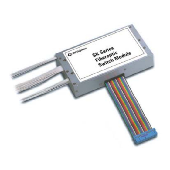
26-pin parallel interface. It connects a single fiberoptic channel to any of N (up to 26) channels. Small and rugged, the SK Series switch module is designed to be used in embedded applications and is available in both single-mode and multimode versions. -
Page 10: Key Features
The SK switch operates on a single 5 V ±5% DC power supply and is controlled through a simple parallel interface consisting of seven data lines, a reset line, a strobe line, and a busy line. Key Features • Up to 26 channels •... -
Page 11: Specifications
Specifications The following optical specifications describe the warranted characteristics of the unit (Table 2). Supplementary specifications describe the typical non-warranted performance of the unit (Table Table 2: Optical Specifications Parameter Typical Maximum Insertion loss single-mode 0.4 dB 0.7 dB multimode 0.4 dB 0.7 dB Return loss... - Page 12 Table 3: Other Specifications Electrical Input voltage 5.0 ±0.25 V DC typical, 6.0 V DC maximum Power consumption 2.20 W steady state Physical Dimensions (W x H x D) 79 x 28 x 140 mm Weight 280 g Environmental Operating temperature 0 to 55 °C Storage temperature -40 to 70 °C...
-
Page 13: Getting Started
Getting Started The SK Series Fiberoptic Switch Module consists of the switch and a ribbon cable with a standard dual row connector. Before Initializing and Operating the Unit Inspect the unit for any signs of damage. Read the user’s manual thoroughly, and become familiar with all safety symbols and instructions to ensure that the unit is operated and maintained safely. -
Page 14: Humidity
Humidity The unit can be operated in environments with up to 95% humidity (non-condensing, 0 to 55 °C). Do not expose it to any environmental conditions or changes to environmental conditions that can cause condensation to form inside the unit. Warning •... -
Page 15: Mounting Considerations
2. Apply optical grade isopropyl alcohol or optical grade ethanol (do not use rubbing alcohol) to a small area of a lint-free towel and rub the end of the ferrule over the wet area. 3. Wipe the ferrule on a dry area of the lint-free towel. 4. - Page 16 Table 4: Pin Assignment Signal Description power ground power ground Busy busy output: low = idle, high = switching data line 0 input, least significant bit (LSB) Error reset error output, low = normal, high = switch mechanism position check failed (channel position is verified when the SK switch is reset) data line 1 not connected...
-
Page 17: Fiber Exit
All transistor-to-transistor logic (TTL) inputs and outputs are pulled high to 5 V DC through 10 K ohm resistors. For inputs, the maximum low level output is 0.8 V, and the minimum high level is 2.0 V. For outputs, the maximum low level output is 0.5 V, and the minimum high level is 4.0 V. Fiber Exit The fibers always exit from the back of the unit (Figure 5), but the order can vary with the unit. -
Page 19: Operating And Maintenance Instructions
Operating and Maintenance Instructions External Description The top and side views of the SK switch module are shown in Figure 6. Figure 6: Top and Side Views of the SK Switch Connections The way that the SK switch interfaces with the input/output lines of a typical host controller is shown in Figure 7. -
Page 20: Pin Functional Description
Figure 7: Typical Controller Connections Pin Functional Description Data Lines (D0 to D6) Valid channel numbers are strobed in through the data lines on high-to-low transitions of the /Strobe line. When a new channel is strobed in, the SK switch immediately selects the channel. The channel number is represented as a binary number present on the data lines having the values listed in the channel address in Table 5. - Page 21 Table 5: Channel Address Table /Reset channel # 0 (reset) The value 0 indicates that the input is set low (for example, <0.8 V DC); the value 1 indicates that the input is set high. For example, to select channel 9, D3 must be set high and the rest of the data lines must be set low.
-
Page 22: Reset Input Line
If the test fails, the Error line goes high and stays high until a self-test operation is evoked again (assuming the self-test passes on the next attempt). The error most often indicates a mechanical fault. For more information, contact JDS Uniphase. Timing When a channel address is strobed in from the data lines, the reset command is strobed in from the /Reset line. -
Page 23: Timing Key
Timing Key The timing key symbols and values are listed in Table 6. Table 6: Timing Key Symbol Minimum Maximum tdh, data hold time 20 µs – tstr, strobe pulse width 1 µs – tmv, switching cycle time – 0.55 ms trh, reset hold time 20 µs –... -
Page 25: Programming Guide
Programming Guide Testing the Switch The SK switch module can be controlled through a PC parallel printer port. An appropriately wired cable is required (Table 7). Table 7: SK-Switch-to-PC-Printer-Port-Connection From Line SK Switch Power Parallel-Port Adapter Identification 26-Pin, IDC Connector Supply 25-Pin, D-sub Connector Busy... -
Page 26: Programming Examples
'SET STROBE LOW OUT &H37A, 0 'SET STROBE HIGH 'CLEAR THE USER SCREEN LOCATE 6, 23 PRINT "JDS Uniphase - SK SWITCH TEST" LOCATE 11, 23 PRINT "PRESS I TO INCREMENT CHANNEL" LOCATE 12, 23 PRINT "PRESS D TO DECREMENT CHANNEL"... -
Page 27: Service
• The unit does not pass the initial inspection In the event of carrier responsibility, JDS Uniphase will allow for the repair or replacement of the unit while a claim against the carrier is being processed. Returning Shipments to JDS Uniphase JDS Uniphase only accepts returns for which an approved Return Material Authorization (RMA) has been issued by JDS Uniphase sales personnel.