
Related Manuals for JDS Uniphase HA9 Series


Summary of Contents for JDS Uniphase HA9 Series
- Page 1 sales@artisantg.com artisantg.com (217) 352-9330 | Click HERE Find the VIAVI Solutions / JDSU HA9W1+20KSC1 at our website:...
- Page 2 HA9 SERIES EXTENDED RANGE PROGRAMMABLE OPTICAL ATTENUATOR User’s Manual Artisan Technology Group - Quality Instrumentation ... Guaranteed | (888) 88-SOURCE | www.artisantg.com...
- Page 3 Artisan Technology Group - Quality Instrumentation ... Guaranteed | (888) 88-SOURCE | www.artisantg.com...
-
Page 4: Table Of Contents
Operating Environment ....................13 Temperature ......................13 Humidity......................13 Ventilation......................13 Storing and Shipping.....................13 Claims and Repackaging...................13 Returning Shipments to JDS Uniphase .............14 Cleaning Connectors.....................14 Connecting and Setting the GPIB Interface ..............15 Connecting the RS232 Interface ...................16 Checking Optional Connections ..................17 Operating and Maintenance Instructions ................18 Front Panel........................18... - Page 5 Setting the Calibration Wavelength................21 Setting the User Slope ....................22 Optimizing the Calibration Wavelength..............22 Storing a User Slope..................22 Setting the Display Offset....................23 Setting the Display Offset in ATT Mode.............23 Setting the Display Offset in PWR Mode ............23 Setting the Power......................24 Controlling the Driver.....................24 Resetting the Attenuator ....................24 Checking Attenuator Calibration..................24 Required Equipment ..................24...
- Page 6 Status Commands .....................76 System Commands ...................80 User Commands....................80 IEEE 488.2 Common Commands .................81 For sales and service information, contact JDS Uniphase or your local representative. JDS Uniphase Corporation 570 West Hunt Club Road Nepean, Ontario, Canada K2G 5W8 Phone: 613 727-1303 Fax: 613 727-8284 E-mail: sales@jdsunph.com...
-
Page 7: Safety Information, Instructions, And Symbols
Safety Information Classification The HA9 Series Extended Range Programmable Optical Attenuator consists of an exposed metal chassis that is connected directly to earth via a power cord and, therefore, is classified as a Class 1 instrument. Class 1 refers to equipment relying on ground protection as a means of shock protection. -
Page 8: Safety Instructions
Failure to comply with any of these instructions or with any precaution or warning contained in the user’s manual is in direct violation of the standards of design, manufacture, and intended use of the unit. JDS Uniphase assumes no liability for the customer’s failure to comply with any of these safety requirements. - Page 9 circuit the fuse. • Unless absolutely necessary, do not attempt to adjust or perform any maintenance or repair procedure when the unit is opened and connected to a power source. • Repairs are to be carried out only by a qualified professional. •...
-
Page 10: Safety Symbols
Safety Symbols The following symbols and messages can be marked on the unit (Table 1). Observe all safety instructions that are associated with a symbol. Table 1: Safety Symbols Symbol Description Laser safety. See the user’s manual for instructions on handling and operating the unit safely. -
Page 11: Compliance
Compliance FCC Compliance The Federal Communications Commission (FCC) of the United States of America requires that equipment operating in that country does not cause interference to communications. The unit has been tested and found to comply with the limits for a Class A digital device, pursuant to Part 15 of Title 47 of the Code of Federal Regulations for Radio Frequency Devices. -
Page 12: Ul Compliance
against electrostatic discharges; and that the equipment be immune to all electrical shock wave disturbances. As of 1997, measures have been added to test for fire hazard, electric shock hazard, and also external exposure to other forms of energy. The requirements specified by directive 89/336/EEC are as follows. CE compliance requires that the manufacturer or its authorized representative established within the Community affix the EC conformity mark to the apparatus or else to the packaging, instructions for use, or guarantee certificate. -
Page 13: General Information And Specifications
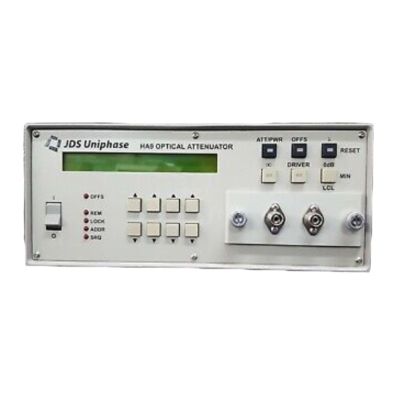
General Information and Specifications General Information This user’s manual for the HA9 Series Extended Range Programmable Optical Attenuator contains complete operating instructions. The HA9 Series Extended Range Programmable Optical Attenuator (Figure 1) gives an extended attenuation range (100 dB) and high resolution (0.01 dB) for testing power meters and for general test and laboratory work. -
Page 14: Key Features
When combined with a light source, the attenuator can be used for EDFA testing or for calibrating the linearity of power meters. In addition, the attenuator can be used for loss simulation and for measuring bit error rate (BER) curves and the dynamic range of receivers (Figure 2). -
Page 15: Applications
Applications • Testing erbium doped fiber amplifiers (EDFAs) • Testing and/or calibrating the linearity of power meters • Measuring bit error rate curves • Measuring the dynamic range of receivers • Simulating loss Standard Accessories • LabVIEW drivers diskette and user’s manual •... -
Page 16: Specifications
Specifications The following optical specifications describe the warranted characteristics of the unit ( Table 2). Supplementary specifications describe the typical non-warranted performance of the unit (Table 3). Table 2: Optical Specifications Parameter Standard Wide Wavelength range 1200 to 1700 nm 750 to 1700 nm Attenuation ≥60... - Page 17 Total of discreet reflections, not including distributed reflection in fiber. Table 3: Other Specifications Electrical Input voltage 90 to 240 V AC, 50 to 60 Hz Power consumption 80 VA maximum Physical Dimensions (W x H x D) 21.2 x 8.9 x 35.5 cm 19 inch (48.26 cm) 2U high, ½...
-
Page 18: Getting Started
Getting Started The HA9 Series Extended Range Programmable Optical Attenuator consists of the attenuator unit, an AC power cord, rack-mount kit, and HA9 LabVIEW software. Before Initializing and Operating the Unit Inspect the unit for any signs of damage. Read the user’s manual thoroughly, and become familiar with all safety symbols and instructions to ensure that the unit is operated and maintained safely. -
Page 19: Operating Environment
• The unit does not pass the initial inspection In the event of carrier responsibility, JDS Uniphase will allow for the repair or replacement of the unit while a claim against the carrier is being processed. Getting Started – 13... -
Page 20: Returning Shipments To Jds Uniphase
JDS Uniphase only accepts returns for which an approved Return Material Authorization (RMA) has been issued by JDS Uniphase sales personnel. This number must be obtained prior to shipping any material to JDS Uniphase. The owner’s name and address, the model number and full serial number of the unit, the RMA number, and an itemized statement of claimed defects must be included with the return material. -
Page 21: Connecting And Setting The Gpib Interface
• Lint-free towels (for example, 10 x 10 cm or 4 x 4 in HydroSorb III wipers, available from http://www.focenter.com/acctech/hydrosobr_wipers.htm) • Optical grade isopropyl alcohol or optical grade 200° ethanol (do not use rubbing alcohol, which contains 30% water) To clean the connectors: 1. -
Page 22: Connecting The Rs232 Interface
Figure 4: GPIB Pin Assignment 2. Connect the cable to the remote terminal and to the IEEE488 (GPIB) port at the back of the attenuator. Caution Tighten the connector lock screws by hand. Do not use a screwdriver. Next, set or reset the GPIB address and the command set: 1. -
Page 23: Checking Optional Connections
Figure 5: RS232 Pin Assignment 2. Connect the cable to the remote terminal and to the RS232C port at the back of the attenuator. Driver Pin Assignment The driver pin assignment is shown in Figure 6. Figure 6: Driver Pin Assignment Caution Do not exceed 100 mA. -
Page 24: Operating And Maintenance Instructions
Operating and Maintenance Instructions Front Panel The front of the attenuator is shown in Figure 7. Figure 7: Front of the Attenuator (varies with model) Operating Keys The operating keys are described in Table 4. Table 4: Operating Keys Description I / O Power on (I) /off (O) switch ATT/PWR... -
Page 25: Status Leds
Description When held down for one second, sets the unit to the minimum loss position Increases ( )/decreases ( ) the attenuation, power offset, and wavelength calibration settings. Each pair controls a digit in the corresponding position displayed on the LCD (except for wavelength setting). -
Page 26: Setting Operating Mode And Using The Attenuator
Setting Operating Mode and Using the Attenuator The attenuator functions in Attenuation (ATT) mode or in output Power (PWR) mode. In ATT mode, the attenuator displays attenuation in dB. Normally, the attenuation displayed on the front panel is relative to the 0 dB reference position of the attenuating optical filter inside the attenuator. -
Page 27: Turning The Beam Block On Or Off
Figure 9: Using the Attenuator Turning the Beam Block On or Off The beam block function uses a transistor to drive a 5 V relay which, when activated, moves a blocking element in front of the light beam. The relay actuator is attached to the beam-blocking element, which provides an infinite attenuation by blocking the optical path. -
Page 28: Setting The User Slope
3. When the required wavelength setting is reached, press ATT/PWR to store the setting and return to the attenuation or power display. A correction factor curve is adjusted for each attenuator to provide optimum performance with a laser diode source at 1300 and 1550 nm. The user can increase or decrease the calibration wavelength of the HA9 attenuator to find a better slope correction factor for the source in use. -
Page 29: Setting The Display Offset
4. Press the λ key. 5. Press the 0 dB key. The calibration wavelength changes to “user”, and the displayed attenuation changes to 10.00 dB. 6. To cancel the user slope, reset the attenuator or switch to λ mode, and then press the corresponding key. -
Page 30: Setting The Power
Setting the Power The attenuator has no internal power measurement capability, but by using the display-offset feature of the attenuator, the display can be matched with the help of an external power meter. To set the power: 1. Ensure that the attenuator is set to PWR mode (the display is in dBm). 2. - Page 31 • Various connectors • Isolator (optional) Operating and Maintenance Instructions – 25 Artisan Technology Group - Quality Instrumentation ... Guaranteed | (888) 88-SOURCE | www.artisantg.com...
-
Page 32: Verifying Calibration
Verifying Calibration To verify calibration: 1. With the attenuator powered off (O), clean all optical connections before each connection with an alcohol-soaked swab. See the Cleaning Connectors section. 2. To avoid reflection-induced source power changes, ensure that the connector to the power meter has low reflection or that the source has an isolator. -
Page 33: Verifying Insertion Loss
Verifying Insertion Loss To verify insertion loss: 1. Zero the power meter. 2. Connect the source directly to the power meter by bypassing the attenuator and connecting the two jumpers or pigtails together (Figure 11). Figure 11: Insertion Loss Verification Setup 3. - Page 34 Figure 12: Removing the Connector Panel 3. Remove the connectors from the connector bulkheads. 4. Clean the connector ends and the bulkhead mating sleeves with a lint-free tissue and alcohol. 5. Reinstall the connectors into the connector bulkheads. 6. Reinstall the connector panel, guiding the fibers back to ensure that they do not bend sharply.
-
Page 35: Programming Guide
Programming Guide The following programming instructions for the HA9 attenuator are intended for users who are familiar with remote interfaces and how to send or receive messages over a device. A detailed description of the GPIB interface is in ANSI/IEEE Std. 488.1-1987 IEEE Standard Digital Interface for Programmable Instrumentation published by the Institute of Electrical and Electronics Engineers. -
Page 36: Switching Between Remote And Local Operation
In SCPI mode, the message terminating sequence is automatically set to <LF>. Switching between Remote and Local Operation The attenuator is automatically placed in Remote mode as soon as a computer communicates with the attenuator via the GPIB or RS232 port using the SCPI or HA command set. The REM status LED lights to indicate that the attenuator has transitioned to Remote mode and can accept commands from the GPIB or RS232 port, and that all front panel keys except LCL are locked out. -
Page 37: Rs232 Programming Examples
Table 7: RS232 Functions Name Symbol Pin Number Signal Direction transmitted data received data request to send clear to send data terminal ready signal ground — The data protocol is permanently set to 1200 baud, ASCII character code with eight bits per character, one stop bit, and no parity bit. -
Page 38: Ha9 And Hpm Command Sets
Querying Status This example queries and displays the current attenuation setting. OPEN "COM2:1200,N,8,1" FOR RANDOM AS #3 PRINT#3, "ATT?" INPUT#3, A PRINT A Reading the Status Register The serial polling function is not supported on any RS232C interface, but the STB? command can be used to query the status register because it performs the same function as serial polling. -
Page 39: Command Parser Rules
Command Parser Rules • Commands consist of a mnemonic (for example, WVL) and, if required, a data parameter (for example, 1300NM). The mnemonic and the parameter must be separated by at least one space. • Parameters can be entered in various formats. For example, 1300nm, 1.303-6 mm, and 0.0000013M are recognized as the same value. -
Page 40: Ha9/Hpm Operation Commands
HA9/HPM Operation Commands Beam Block Controls the on/off status of the beam block: • 0 = beam block off • 1 = beam block on RESET Reset Returns the attenuator to the following default settings: • WVL = 1310 nm •... - Page 41 STPWR Display Offset (PWR Mode) Sets the display offset in PWR mode so that the display matches the power meter reading. The default unit is dBm. Attenuation Sets the attenuation of the attenuator relative to the 0 dB reference position; that is, it is independent of the attenuation display offset.
-
Page 42: Ha9/Hpm Query Commands
HA9/HPM Query Commands Beam Block Status Returns the on/off status of the beam block: • 0 = beam block off • 1 = beam block on WVL? Calibration Wavelength Returns the calibration wavelength: • WVL? returns the current calibration wavelength •... - Page 43 CAL? Display Offset (ATT Mode) Returns the display offset in ATT mode: • CAL? returns the current display offset • CAL? MIN returns the minimum display offset • CAL? MAX returns the maximum display offset PCAL? Display Offset (PWR Mode) Returns the display offset in PWR mode: •...
- Page 44 Returns a string that identifies the manufacturer, the HA9 model number, the serial number (or 0 if unavailable), and the firmware level, for example, JDS UNIPHASE HA9x,01, 0,00.100 (where x = S for standard model and x = L for wide model).
-
Page 45: Status Reporting And Service Request Control
Always returns 1. This command serves only to maintain the compatibility of the attenuator to the HP 8157A attenuator. LRN? Learn In HA and HP mode, returns a 58-character string containing a summary of the current settings of the attenuator. The string is formatted as follows: •... -
Page 46: Srq Mask Register
Status Register Bit 7 Bit 6 Bit 5 Bit 4 Bit 3 Bit 2 Bit 1 Bit 0 self-test service syntax message settled parameter error request error available error • Bit 7 (self-test error) is set if a calibration error was detected after power-up or after the self-test query (TST?) was executed. -
Page 47: Gpib Programming Examples
The SRQ mask register is cleared by powering up the attenuator, by the CLR command, or by the universal device clear command (DC1). SRQ Mask Register Bit 7 Bit 6 Bit 5 Bit 4 Bit 3 Bit 2 Bit 1 Bit 0 self-test syntax... - Page 48 PRINT #1, "RESET" PRINT #1, "GPIBEOS IN LF" ' setting terminating characters to LF PRINT #1, "GPIBEOS OUT LF" DIM ATTEN AS SINGLE DIM WAV AS INTEGER PRINT #1, "OUTPUT 05;:INP:OFFS 10" ATTEN = 30.0 WAV = 1550 PRINT #1, "OUTPUT 05;:INP:ATT";STR$(ATTEN);";WAV";STR$(WAV);"NM" Querying Status This example queries and displays the current attenuation setting: OPEN "GPIB0"...
- Page 49 Generating a Service Request Interrupt A service request interrupt is generated when the attenuator completes changing the attenuation setting.This example tests the service request interrupt function. It unmasks the settled bit in the SRQ mask register and sends a new attenuation setting. OPEN "GPIB0"...
- Page 50 ' Like this... PRINT#1, "OUTPUT 05;WVL " ; wave ; ";CAL "; cal ; ";ATT " ; atten ;";D " ; block ' Attenutor settings are now restored in ATT mode Sending Queries This example queries the attenuation and the state of the beam block: OPEN "GPIB0"...
-
Page 51: Scpi Command Set
PRINT #1, "ENTER 05" INPUT #2, CONDREG LOOP UNTIL (CONDREG AND 2 = 2) FOR J = 1 TO 10000:NEXT ' wait for power meter to settle GOSUB METER P1 = POWER PRINT #1, "OUTPUT 05;:INP:ATT 40" ' change attenuation setting ' wait in loop until attenuator settles PRINT #1, "OUTPUT 05;:STAT:OPER:EVENT?"... -
Page 52: Program Message Formats
Program Message Formats A program message consists of a command header, followed by its required parameters. The parameters must be separated from the command header by a space, for example, :INPUT:ATTENUATION 10. Multiple parameters must be separated by a comma (,). Each program message can contain one or more message units. - Page 53 :INP:OFFS 20; WAV 1200 NM :INP:OFFS 20; :INP:WAV 1200 NM :INP:OFFS:DISP 20; Programming Guide – 47 Artisan Technology Group - Quality Instrumentation ... Guaranteed | (888) 88-SOURCE | www.artisantg.com...
-
Page 54: Default Commands
The following program messages are not valid: :INP:OFFS 20; INP:WAV 1200 NM (no colon before second command) :INP:OFFS 20; DISP 1 (DISP command at different level than OFFS) :INP:OFFS:DISP 1;WAV 1200 NM (WAV command at different level than DISP) Default Commands Default commands do not need to be explicitly included in the command path. -
Page 55: Suffixes
• Boolean—0, 1, ON, OFF. Any other numeric value sent is rounded to the nearest integer. If the resulting integer is anything but 0, it is interpreted as 1. • Character—A character string that contains no more than 12 characters. Each character in the string must be either an uppercase or a lowercase letter, a digit (0 to 9), or an underscore (_). -
Page 56: Response Formats
Table 8: Valid Multipliers Multiplier Value 1E18 1E15 1E12 1E-3 1E-6 1E-9 1E-12 1E-15 1E-18 For example, for the wavelength command that has a base unit of meter (m), the following message formats are valid: :INPUT:WAVELENGTH 1200NM :INPUT:WAVELENGTH 1.6e-06 M :INPUT:WAVELENGTH 1.4e-09 KM The following message formats are not valid: :INPUT:ATT 50 NDB... -
Page 57: Overview Of Implemented Status Structures
Each response message can contain multiple pieces of data. Data within a response message is separated by a comma, for example, the query *IDN? returns JDS UNIPHASE,HA9X,0,YY.YYY. Overview of Implemented Status Structures There are three distinct status data structures implemented in the attenuator: •... - Page 58 Figure 13: Operational and Questionable Status Data Structures Programming Guide – 52 Artisan Technology Group - Quality Instrumentation ... Guaranteed | (888) 88-SOURCE | www.artisantg.com...
- Page 59 Figure 14: Status Report Model Programming Guide – 53 Artisan Technology Group - Quality Instrumentation ... Guaranteed | (888) 88-SOURCE | www.artisantg.com...
-
Page 60: Status Byte Register
Status Byte Register The status byte register contains the summary bits for each of the structures implemented in the attenuator and either the master summary bit (MSB) or the request for service bit (RQS). Status Byte Register Bit 0 Bit 1 Bit 2 Bit 3 Bit 4... -
Page 61: Service Request Enable Register
Service Request Enable Register The service request enable register determines which summary bits in the status byte register can generate service requests. If a summary bit in the status register is set to 1 and the corresponding bit in the service request enable register is also set to 1, a service request is generated by the attenuator. -
Page 62: Standard Event Status Enable Register
• Bit 4 (execution error) is set when an execution error is detected by the attenuator, for example, if a command parameter is out of the range of the attenuator or if a valid program message cannot be executed due to some condition in the attenuator. •... -
Page 63: Operation And Questionable Event Registers
Operation and Questionable Event Registers Event registers reflect changes in the conditions of the attenuator. Each bit in the operation event register and the questionable event register is associated with a bit in the corresponding condition register. Depending on the values of the positive transition register and the negative transition register, a bit in the event register can be set when the associated bit in the condition register changes from 0 to 1, from 1 to 0, or both. -
Page 64: Operation And Questionable Negative Transition Registers
Operation Positive Transition Register Read with STATus:OPERation:PTRansition? query Written to with STATus:OPERation:PTRansition command Cleared by Power-on Condition Positive Transition Register Read with STATus:QUEStionable:PTRansition? query Written to with STATus:QUEStionable:PTRansition command Cleared by Power-on Operation and Questionable Negative Transition Registers If a bit in the negative transition register is set, then a negative transition (a transition from 1 to 0) in the associated bit in the condition register causes the associated bit in the event register to be set. -
Page 65: Output Queue
Output Queue Responses to query messages are placed in the output queue. This queue is 100 bytes long. When a response is placed in the output queue, the MAV bit in the status register is set. The MAV bit is cleared when the response is sent. If an attempt is made to read the output queue when it is empty and the current program message does not contain a query, a query error bit is set. - Page 66 -109 Missing parameter Fewer parameters were received than the command or query requires. -110 Command header error An error was detected in the command header, but the parser cannot be more specific. -111 Header separator error A character that was not a valid header separator was encountered. -112 Program mnemonic too long The command header contained too many characters.
- Page 67 A valid numeric parameter was received, but the required parameter type is not numeric. -130 Suffix error An error was detected in the suffix sent with the command, but the parser cannot be more specific. -134 Suffix too long The suffix sent with the command was more than 12 characters long. -140 Character data error An error was detected in a character type parameter, but the parser cannot be more specific.
- Page 68 -224 Illegal parameter value A valid parameter type was received, but it did not match any of the permitted values. -240 Hardware error A command cannot be executed due to a hardware error, but the control block cannot be more specific.
-
Page 69: Scpi Command Tree
-430 Query deadlocked The device was deadlocked. Both the input buffer and output queue are full, and the attenuator is unable to continue. Undefined error number An undefined error occurred. SCPI Command Tree All commands other than the IEEE 488.2 common commands are listed in Table 9. The following abbreviations are used in the Command Status column: •... - Page 70 Command Parameters Response Unit Command Status (table continued) :OFFSet? MAX | MIN | DEF 0.00 99.99 Numeric Value 1200NM 1700NM 1310NM :WAVelength MAX | MIN | DEF 1200NM 1700NM 1310NM :WAVelength? :OUTPut [:STATe] Boolean [:STATe?] Boolean| DIS| :APOWeron LAST :APOWeron? :APMode Boolean :APMode?
- Page 71 Command Parameters Response Unit Command Status PTRansition? (table continued) :QUEStionable [:EVENt]? :CONDition? 32,76 :ENABle :ENABle? 32,76 :NTRansition NTRansition? 32,76 :PTRansition PTRansition? :PRESet :SYSTem :ERRor? NRf , String :VERSion? String :UCALibration :USRMode Boolean :USRMode? :SLOPe Numeric Value :SLOPe? Programming Guide – 65 Artisan Technology Group - Quality Instrumentation ...
-
Page 72: Common Commands
Common Commands Clear Status Command Syntax *CLS Function Clears the following queues and registers: • Error queue • Standard event status register • Status byte register • Operation event register • Questionable event register If *CLS is sent immediately after a message terminating sequence, both the output queue and the MAV bit in the status byte register are cleared. - Page 73 Example *IDN? returns JDS UNIPHASE, HA9X, 0, YY.YYY Operation Complete Command Syntax *OPC Function Causes the attenuator to set the OPC bit in the standard event status register when all pending operations have been completed. Example *OPC Operation Complete Query...
- Page 74 Programming Guide – 68 Artisan Technology Group - Quality Instrumentation ... Guaranteed | (888) 88-SOURCE | www.artisantg.com...
- Page 75 Save Command *SAV<space><numeric value> where 1 ≤ <numeric value> ≤ 9 Syntax Function Stores the current state of the attenuator in local memory; as many as nine states can be stored. For each state, the following settings are stored: • Total attenuation •...
-
Page 76: Display Commands
*WAI Command Syntax *WAI Function Prevents the attenuator from executing any further commands or queries until all pending operations have been completed. Example :INP:ATT 10;WAI;INP:OFF? prevents the attenuator from reading the offset until it has completed setting the attenuation to 10 dB. DISPlay Commands :DISPlay:BRIGhtness :DISPlay:BRIGhtness<space><numeric value>... -
Page 77: Input Commands
INPut Commands :INPut:ATTenuation Syntax :INPut:ATTenuation <space> <numeric value> [dB] Function Sets the total attenuation to the parameter value by changing the actual attenuation. Because the total attenuation includes the offset, the actual attenuation of the attenuator is set according to the following formula: - Offset actual = total... - Page 78 :INPut:LCMode Syntax :INPut:LCMode <space> <boolean> Function Sets the process by which the wavelength calibration is implemented when the wavelength is changed. A boolean value of 1 or ON activates LCM mode. In LCM mode, the total attenuation remains fixed when the wavelength is changed, for example, the attenuator prism is moved to give the same attenuation at the new wavelength.
- Page 79 :INPut:OFFSet? Syntax :INPut:OFFSet? [<space> <MIN|MAX|DEF>] Function Returns the current setting of the display offset. The query accepts the parameters MIN, MAX, and DEF to return the minimum, maximum, or default value (respectively) for the display attenuation at the current offset setting. Example :INP:OFFS 16;OFF? returns 16.
-
Page 80: Output Commands
OUTPut Commands :OUTPut:APMode Syntax :OUTPut:APMode <space> <boolean> Function Sets whether the actual attenuation of the attenuator is set by changing the total attenuation or by changing the through power. When absolute power mode is set to ON, the actual attenuation is set by setting the through power rather than the total attenuation. - Page 81 :OUTPut:DRIVer? Syntax :OUTPut:DRIVer Function Returns 1 if the 5 V output is on and 0 if the 5 V output is off. Example :OUTP:DRIV OFF;DRIV? returns 0. :OUTPut:POWer Syntax :OUTPut:POWer <space> <numeric value> [dBm] Function Sets the through power of the attenuator. The through power is used to set the actual attenuation of the attenuator.
-
Page 82: Status Commands
:OUTPut[:STATe]? Syntax :OUTPut[:STATe]? Function Returns the state of the beam block: 1 if the beam block is out of the beam and 0 if the beam block is in the beam. Example :OUTP ON;STAT? returns 1. :OUTP OFF;STAT? returns 0. :OUTPut[:STATe]:APOWeron Syntax :OUTPut[:STATe]:APOWeron <space>... - Page 83 :STATus:OPERation:ENABle Syntax :STATus:OPERation:ENABle <space> <NRf> Function Sets the bits in the operation enable register. The NRf value is rounded to the nearest integer and converted to a binary number. The bits of the register are set to match the bit values of the binary number. Example :STAT:OPER:ENAB 32.8 sets bit 0 and bit 5 of the operation enable register to :STATus:OPERation:ENABle?
- Page 84 Example :STAT:OPER:PTR 255 sets the bits of the operation positive transition register to 0000000011111110. :STATus:OPERation:PTRansition? Syntax :STATus:OPERation:PTRansition? Function Returns the contents of the operation positive transition register as an integer that, when converted to a binary number, represents the bit values of the register.
- Page 85 :STATus:QUEStionable:NTRansition Syntax :STATus:QUEStionable:NTRansition <space> <NRf> Function Sets the bits of the questionable negative transition register. The NRf value is rounded to the closest integer and converted to a binary number. The bits of the register are set to match the bits of the binary number. Example :STAT:QUES:NTR 256 sets the bits of the questionable negative transition register to 0000000011111111.
-
Page 86: System Commands
System Commands :SYSTem:ERRor? Syntax :SYSTem:ERRor? Function Returns the next error message in the error queue. Because the error queue is an FIFO queue, the error returned is the oldest unread error. The error message consists of an error number followed by an error message, for example, 0, No Error See the Error Queue section for a list of error numbers and their associated messages. -
Page 87: Ieee 488.2 Common Commands
:UCALibration:SLOPe :UCALibration:SLOPe <space> <numeric value> Syntax Function Sets the user slope. The slope of the attenuator can be matched to a power meter for a given source by adjusting the user slope. This command also accepts the parameters MIN, MAX, and DEF. The minimum value for the slope is 0.5, the maximum value is 2.0, and the default value is 1.0.