Table of Contents
Advertisement
Mar. 2008
Table of Contents
Cautionary Notes ..............................................................2
Main Specifications ...........................................................3
Location of Controls .........................................................4
Location of Controls Parts List........................................5
Exploded View ..................................................................6
Exploded View Parts List.................................................8
Important Notes When Disassembling..........................9
Wiring Diagram Parts List .............................................10
Parts List ...........................................................................12
Verifying the Version Number......................................15
Saving and Loading Data...............................................15
Performing a Factory Reset............................................15
Updating the System ......................................................15
Test Mode .........................................................................16
Copyright © 2008 Roland Corporation
All rights reserved. No part of this publication may be reproduced in any form without the written permission
of Roland Cororation.
Circuit Board (Main Board) ...........................................24
Circuit Diagram (Main Board: 1/5) ..............................26
Circuit Diagram (Main Board: 2/5) ..............................28
Circuit Diagram (Main Board: 3/5) ..............................30
Circuit Diagram (Main Board: 4/5) ..............................32
Circuit Diagram (Main Board: 5/5) ..............................34
EXP Board) .......................................................................36
Circuit Diagram (SW VR Board) ...................................38
Circuit Diagram (Pedal Board)......................................40
Circuit Diagram (Bank Board).......................................42
Circuit Diagram (ENC Board) .......................................42
Circuit Diagram (EXP Board) ........................................43
Determination of Main Board Model ...........................43
17058541E0
SERVICE NOTES
Issued by RJA
Printed in Japan (0290) (CC-KWS)
GT-10
Advertisement
Table of Contents

Related Manuals for Roland Boss GT-10


Summary of Contents for Roland Boss GT-10
-
Page 1: Table Of Contents
Circuit Diagram (EXP Board) ........43 Test Mode .................16 Determination of Main Board Model ......43 Copyright © 2008 Roland Corporation All rights reserved. No part of this publication may be reproduced in any form without the written permission of Roland Cororation. -
Page 2: Cautionary Notes
Mar. 2008 GT-10 Cautionary Notes Before beginning the procedure, please read through this document. The matters described may differ according to the model. Back Up User Data! User data may be lost during the course of the procedure. Refer to “Saving and Loading Data”... -
Page 3: Main Specifications
132 x 64 dots graphic LCD (backlit LCD) * AF method (Adaptive Focus method) 7 segments, 3 characters LED This is a proprietary method from Roland & BOSS that vastly improves the signal-to-noise (S/N) ratio of the A/D and D/A converters. Connectors... -
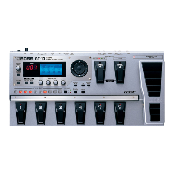
Page 4: Location Of Controls
Mar. 2008 GT-10 Location of Controls fig.panel-GT-10.eps... -
Page 5: Location Of Controls Parts List
Mar. 2008 GT-10 Location of Controls Parts List Parts Part Code Part Name Description Q’ty F3229203R0 ROTARY POTENTIOMETER RD901F-40-15F-B10K-0068 G2477526R0 R-KNOB INDEX G2527521R0 PANEL F5229817R0 8SEG LED A-553SR-A B/W G2567171R0 DISPLAY COVER F5229821R0 LCD UNIT W/WIRING KMC13264-H-00-SPF F5229820R0 LED (RED) L-7104SRT F5229818R0 LED (GREEN) -
Page 6: Exploded View
Mar. 2008 GT-10 Exploded View fig.bunkai.eps@L... - Page 7 Mar. 2008 GT-10 fig.bunkai.eps@R...
-
Page 8: Exploded View Parts List
Mar. 2008 GT-10 Exploded View Parts List Parts Part Code Part Name Description Q’ty G2027952R0 TOP COVER G2207423R0 BOTTOM COVER G2237632R0 GUARD PLATE G2207422R0 GUARD ESCT G2567171R0 DISPLAY COVER G2527521R0 PANEL G2637107R0 RUBBER SW G2147806R0 STAY (POM) G2257331R0 INSULATING SHEET G2497021R0 KEYTOP UNIT S G2497019R0... -
Page 9: Important Notes When Disassembling
Mar. 2008 GT-10 Screw Part Code Part Name Description Q’ty H5049003R0 SCREW M4X4 H5049004R0 SCREW M3X10.5 40563989 SCREW 4X8 TAPTITE S BINDING NI 40019123 SCREW 3X8 BINDING TAPTITE S BZC 40011278 SCREW 3X8 BINDING TAPTITE P FE ZC 40017934 SCREW M3X6 PAN MACHINE W/SW+PW(L) FE ZC 40342712 SCREW M3X6... -
Page 10: Wiring Diagram Parts List
Mar. 2008 GT-10 Wiring Diagram Parts List fig.block-wiring.eps@L Part Code Part Name Description Q’ty F3417194R0 WIRING EXP 3PIN F3417195R0 RIBBON CABLE ENC 3PIN F3417196R0 WIRING SW 12PIN F3417197R0 WIRING AD 7PIN F3417198R0 WIRING LED 11PIN F3417199R0 WIRING PEDAL 13PIN F3477081R0 RIBBON CABLE PEDAL 9PIN * LCD KMC13264-H-00-SPF (#F5229821R0) includes the following LCD UNIT (LCD FPC, BACKLIGHT WIRING.) - Page 11 Mar. 2008 GT-10 fig.block-wiring.eps@R...
-
Page 12: Parts List
Mar. 2008 GT-10 Parts List fig.-part1-e.eps Due to one or more of the following reasons, SAFETY PRECAUTIONS: parts with parts code ******** cannot be supplied as service parts. The parts marked have safety-related characteristics. Use only listed parts for replacement. •... - Page 13 Mar. 2008 GT-10 02453056 IC (LED DRIVER) BU2090FS-E2 IC102 on SW VR Board F5209167 IC (TTL) 74HC4052D IC101 on SW VR Board DIODE F5229818R0 LED (GREEN) L-7104SGT LED113 on SW VR Board, LED305 on Bank Board F5229819R0 LED (RED) L-7104SURC-E LED101, LED102, LED103, LED104, LED106, LED107, LED108, LED109, LED110, LED111 on SW VR Board...
- Page 14 Mar. 2008 GT-10 SCREWS H5039707R0 WASHER M6 T1NI H5069004R0 U-NUT M6 H5039520R0 G2637118R0 INSULATING WASHER 14.5X9.2 H5069003R0 BOLT HEX M6X67 H5039521R0 NUT M7 H5039510R0 NUT M9X12X2T NI H5039158R0 WASHER M9X14X0.5T NI H5019115R0 SCREW 3X8 PAN TAPPING B1 BZC H5049003R0 SCREW M4X4 H5049004R0 SCREW M3X10.5 H5039126...
-
Page 15: Verifying The Version Number
Mar. 2008 GT-10 Verifying the Version Use System ~ Temp to select the items to send. fig.bulkdmp3.eps Number Start up in the Test Mode. Hold down [OUTPUT SELECT] and [SYSTEM] and switch on the power. * Continue holding down these buttons until 1: VERSION is displayed on the screen. -
Page 16: Test Mode
• DIGITAL IN-compatible device x 1 (device that converts digital audio 10. AMP CTRL p. 19 Jack signal to analog audio signals: Roland DA-400 or the like) Testing of the USB Circuitry and 11. USB&D.OUT p. 19 DIGITAL OUT Circuitry •... - Page 17 Mar. 2008 GT-10 0. Starting the Test Mode Press [EXIT]. Press [CATEGORY/ENTER] to go back to the test-item selection screen. Hold down [OUTPUT SELECT] and [SYSTEM] and switch on the power. * Continue holding down these buttons until a screen like the one shown below 2.
- Page 18 Mar. 2008 GT-10 6. PARAM KNOB Press [ ] to display the screen shown below. fig.3lcdenc3.eps Testing of the PARAMETER Controls fig.6paramknob2.eps Verify that the LCD screen has no missing dots. Press [ ] to display the screen shown below. Turn the PARAMETER 1 control clockwise by 360 degrees or more.
- Page 19 Mar. 2008 GT-10 Apply a load of 25 to 40 kg to the expression pedal at the location in the 9. MIDI figure below. MIDI Test fig.exp-pedal-sw-e.eps fig.9midi2.eps * When no MIDI cable is connected, the message No Connection.. is displayed. Connect the MIDI IN and MIDI OUT jacks using a MIDI cable.
- Page 20 Mar. 2008 GT-10 Verify that the waveform display on the oscilloscope is like that shown in PHONES Test the figure below. Using a cable with a 1/4-inch stereo phone plug (with 33-ohm load fig.11usbdout1.eps resistor), connect the PHONES jack to channel 1 and channel 2 of the oscilloscope and to the left-channel and right-channel monitor speakers.
- Page 21 Mar. 2008 GT-10 Verify that the output waveform display on the oscilloscope is what is 13. INPUT shown in the figure below, and that no sound is played while MUTE is Testing of the INPUT Circuitry displayed on the screen. fig.12out-out2.eps fig.13input2.eps Using the two cables with 1/4-inch phone plugs, connect the OUTPUT L...
- Page 22 Mar. 2008 GT-10 14. RETURN Connect the OUTPUT R jack and the noise meter using a cable with a 1/ 4-inch stereo phone plug, and verify that the noise level is -89 dBu or less Testing of the RETURN Circuitry and the RETURN (DIN audio).
- Page 23 Mar. 2008 GT-10 EXP Pedal Operation-load Test Testing of Load at Which Movement of the Expression Pedal Starts * The power does not need to be on. Depress the heel of the expression pedal all the way. Apply a load near the tip of the expression pedal and verify that the pedal begins to move at a load within the range of 500 to 700 g.
-
Page 24: Circuit Board (Main Board)
Mar. 2008 GT-10 Circuit Board (Main Board) fig.b-main-1.eps... - Page 25 Mar. 2008 GT-10 fig.b-main-2.eps...
-
Page 26: Circuit Diagram (Main Board: 1/5)
Mar. 2008 GT-10 Circuit Diagram (Main Board: 1/5) fig.d-main-1.eps@L... - Page 27 Mar. 2008 GT-10 fig.d-main-1.eps@R...
-
Page 28: Circuit Diagram (Main Board: 2/5)
Mar. 2008 GT-10 Circuit Diagram (Main Board: 2/5) fig.d-main-2.eps@L... - Page 29 Mar. 2008 GT-10 fig.d-main-2.eps@R...
-
Page 30: Circuit Diagram (Main Board: 3/5)
Mar. 2008 GT-10 Circuit Diagram (Main Board: 3/5) fig.d-main-3-e.eps@L... - Page 31 Mar. 2008 GT-10 fig.d-main-3-e.eps@R The value of resistor R252 varies according to the production period. The respective serial numbers are indicated below. ZW78199 or earlier: 10 ohms ZW88200 or later: 47 ohms...
-
Page 32: Circuit Diagram (Main Board: 4/5)
Mar. 2008 GT-10 Circuit Diagram (Main Board: 4/5) fig.d-main-4.eps@L... - Page 33 Mar. 2008 GT-10 fig.d-main-4.eps@R...
-
Page 34: Circuit Diagram (Main Board: 5/5)
Mar. 2008 GT-10 Circuit Diagram (Main Board: 5/5) fig.d-main-5.eps@L... - Page 35 Mar. 2008 GT-10 fig.d-main-5.eps@R...
-
Page 36: Circuit Board (Sw Vr, Pedal, Bank, Enc, Exp Board)
Mar. 2008 GT-10 Circuit Board (SW VR, Pedal, Bank, ENC, EXP Board) fig.b-sw-1.eps... - Page 37 Mar. 2008 GT-10 fig.b-sw-2.eps...
-
Page 38: Circuit Diagram (Sw Vr Board)
Mar. 2008 GT-10 Circuit Diagram (SW VR Board) fig.d-sw-vr.eps@L... - Page 39 Mar. 2008 GT-10 fig.d-sw-vr.eps@R...
-
Page 40: Circuit Diagram (Pedal Board)
Mar. 2008 GT-10 Circuit Diagram (Pedal Board) fig.d-pedal.eps@L... - Page 41 Mar. 2008 GT-10 fig.d-pedal.eps@R...
-
Page 42: Circuit Diagram (Bank Board)
Mar. 2008 GT-10 Circuit Diagram (Bank Board) fig.d-bank.eps Circuit Diagram (ENC Board) fig.d-enc.eps... -
Page 43: Circuit Diagram (Exp Board)
Mar. 2008 GT-10 Circuit Diagram (EXP Board) fig.d-exp.eps Determination of Main Board Model The Main Board Assy for both the GT-10 and the GT-10B uses the same bare circuit board, but the mounted components are different. To distinguish between the two, examine the model identification field on the circuit board. fig.diff-main-GT10.eps... - Page 44 Mar. 2008 GT-10 MEMO...