Table of Contents
Advertisement
AVPEC
AIR HANDLERS
INSTALLATION & OPERATING INSTRUCTIONS
1 Important Safety Instructions ..............................................................2
2 Shipping Inspection .............................................................................3
2.1 Parts .....................................................................................................3
2.2 Handling ...............................................................................................3
3 Codes & Regulations ...........................................................................3
4 Replacement Parts ...............................................................................3
5 Pre-Installation Considerations ..........................................................3
5.1 Preparation ...........................................................................................3
5.2 System Matches ...................................................................................3
5.3 Interconnecting Tubing .........................................................................3
5.4 Clearances ...........................................................................................3
5.5 Horizontal Applications .........................................................................4
6 Installation Location .............................................................................4
6.1 Upflow Installation ................................................................................4
6.2 Horizontal Left Installation ....................................................................4
6.3 Downflow/Horizontal Right Installation .................................................4
7 Refrigerant Lines ..................................................................................7
7.1 Tubing Size ...........................................................................................7
7.2 Tubing Preparation ...............................................................................7
7.3 Tubing Connections ..............................................................................7
8 Condensate Drain Lines ......................................................................8
9 Ductwork ...............................................................................................9
9.1 Return Ductwork ...................................................................................9
10 Return Air Filters ................................................................................9
11 Electric Heat ........................................................................................9
12 Electrical and Control Wiring .......................................................... 11
12.1 Building Electrical Service Inspection ............................................... 11
12.2 Wire Sizing ....................................................................................... 11
12.3 Maximum Overcurrent Protection (MOP) ......................................... 11
12.4 Electrical Connections - Supply Voltage .........................................12
12.4.1 Air Handler Only (Non-Heat Kit Models) ........................................12
12.4.2 Air Handler - Non-Circuit Breaker Heat Kits ..................................12
12.4.3 Air Handler With Circuit Breaker Heat Kit ......................................12
13 Achieving 1.4% & 2% Low Leakage Rate .......................................12
14 Miscellaneous Start-Up Checklist ...................................................12
14.1 Circulator Blower ..............................................................................14
14.2 AVPEC Motor Orientation .................................................................14
15 Troubleshooting ...............................................................................15
15.1 Electrostatic Discharge (ESD) Precautions ....................................15
16 CoolCloud HVAC Phone Application ..............................................15
Outdoor Units ...................................................................................15
17.1 Charging ...........................................................................................16
18 Electric Heater Kit Testing ...............................................................16
19 Dehumidification ..............................................................................16
20 Auxiliary Alarm Switch .....................................................................16
21 Push Buttons ....................................................................................16
Ventilators) ........................................................................................17
23 Ramping Profiles ..............................................................................17
24 Electric Air Cleaning ........................................................................18
25 Max Airflow Table .............................................................................18
26 Air Handler Troubleshooting Matrix ...............................................19
26 Air Handler Troubleshooting Matrix (Continued) ..........................20
27 Air Handler Display ..........................................................................21
27 Air Handler Display (Continued) .....................................................22
27 Air Handler Display (Continued) .....................................................23
28 Wiring Diagram .................................................................................24
29 Dehumidification Control Options ..................................................25
is a registered trademark of Maytag Corporation or its related companies and is used under license. All rights
© 2016-2018, 2021 Goodman Manufacturing Company, L.P.
19001 Kermier Rd., Waller, TX 77484
www.goodmanmfg.com - or - www.amana-hac.com
P/N: IOA-4018F Date: FEBRUARY 2021
Only personnel that have been trained to install, adjust, service
or repair (hereinafter, "service") the equipment specified in this
manual should service the equipment. The manufacturer will
not be responsible for any injury or property damage arising
from improper service or service procedures. If you service this
unit, you assume responsibility for any injury or property dam-
age which may result. In addition, in jurisdictions that require
one or more licenses to service the equipment specified in this
manual, only licensed personnel should service the equipment.
Improper installation, adjustment, servicing or repair of the
equipment specified in this manual, or attempting to install, ad-
just, service or repair the equipment specified in this manual
without proper training may result in product damage, property
damage, personal injury or death.
This device, which was assembled by Goodman Manufacturing
Company, L.P., contains a component that is classified as an intentional
radiator. This intentional radiator has been certified by the FCC: FCC ID
QOQBGM111. And this international radiator has an Industry Canada ID:
IC 5123A-BGM111.
This device complies with Part 15 of the FCC's Rules. Operation of this
device is subject to two conditions:
(1) This device may not cause harmful interference; and
(2) This device must accept any interference received, including
interference that may cause undesirable operation.
And this device meets the applicable Industry Canada technical
specifications.
The manufacturer of the intentional radiator (model no. BGM111) is
Silicon Laboratories Finland Oy, which can be contacted by calling 617-
951-0200. (www.silabs.com)
Goodman Manufacturing Company, L.P. may be contacted by calling 713-
861-2500, or at 19001 Kermier Rd., Waller TX 77484.
(www.goodmanMFG.com)
WARNING
reserved.
Advertisement
Table of Contents
Troubleshooting

Related Manuals for Amana AVPEC Series


Summary of Contents for Amana AVPEC Series
-
Page 1: Table Of Contents
AVPEC © 2016-2018, 2021 Goodman Manufacturing Company, L.P. 19001 Kermier Rd., Waller, TX 77484 AIR HANDLERS www.goodmanmfg.com - or - www.amana-hac.com INSTALLATION & OPERATING INSTRUCTIONS P/N: IOA-4018F Date: FEBRUARY 2021 1 Important Safety Instructions ..............2 2 Shipping Inspection ................3 WARNING 2.1 Parts .....................3... -
Page 2: Important Safety Instructions
1 Important Safety Instructions WARNING The following symbols and labels are used throughout this manual to indicate immediate or potential safety hazards. It is the owner’s and installer’s responsibility to read and To avoid property damage, personal injury or death due to electri- comply with all safety information and instructions accom- cal shock, this unit MUST have an uninterrupted, unbroken electri- cal ground. -
Page 3: Shipping Inspection
2 Shipping Inspection 5 Pre-Installation Considerations Always transport the unit upright; laying the unit on its side 5.1 Preparation or top during transit may cause equipment damage. The in- staller should inspect the product upon receipt for shipping Keep this document with the unit. Carefully read all in- damage and subsequent investigation is the responsibility structions for the installation prior to installing product. -
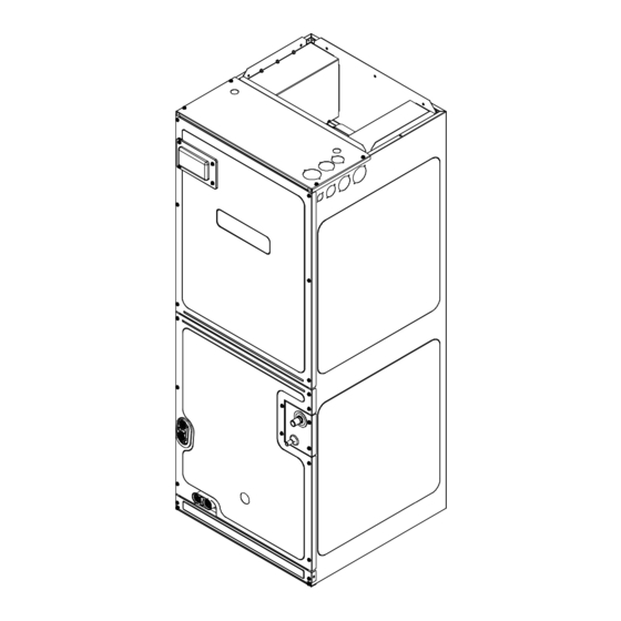
Page 4: Installation Location
6 Installation Location Extension Horizontal Drip Shield NOTE: These air handlers are designed for indoor instal- lation only. Drip Shield Bracket The AVPEC product line may be installed in one of the up- flow, downflow, horizontal left or horizontal right orientations as shown in Figures 3, 4, 5 and 6. - Page 5 1. Before flipping the air handler, remove blower access panel and coil access panel. The coil access panel and tubing panel may remain screwed together during this procedure. Remove and retain the seven (7) screws securing the coil access panel to the cabinet and the six (6) screws securing the blower access panel to the cabinet. 2.
- Page 6 HORIZONTAL LEFT FIGURE 5 HORIZONTAL RIGHT DOWNFLOW FIGURE 6 UPFLOW FIGURE 3 FIGURE 4 Upper Tie Plate Control Deck Blower Access Panel Downflow Bracket Coil Tubing Center Access Support Panel Panel Filter Bracket Filter Access Panel INTERNAL PART TERMINOLOGY Knockout FIGURE 7 EXTERNAL PART TERMINOLOGY NOTE: If removing only the coil access panel from the...
-
Page 7: Refrigerant Lines
6. Reconnect the sensor wires and replace the insulation Coil slides on securing it with wire ties on both sides as shown in Fig- the down ow bracket ure 2-2. Then, secure the wire harness to the corner post using the screw mount wire ties provided. 7. -
Page 8: Condensate Drain Lines
5. Insert liquid line set into liquid tube expansion and NOTE: Units operating in high static pressure applications slide grommet about 18” away from braze joint. may require a deeper field constructed “P” style trap than is shown in Figure 12 to allow proper drainage and prevent 6. -
Page 9: Ductwork
IMPORTANT NOTE: The evaporator coil is fabricated with to the air handler unit’s Serial and Rating plate or the HKS oils that may dissolve styrofoam and certain types of plas- specification sheets to determine the heat kits compatible tics. Therefore, a removal pump or float switch must not con- with a given air handler. -
Page 10: Electrical And Control Wiring
The heating mode temperature rise is dependent upon the HEAT KIT NOMINAL KW system airflow, the supply voltage, and the heat kit size (kW) selected. Use data provided in Tables 4, 5 and 6 to deter- mine the temperature rise (°F). 1000 For installations not indicated above the following formula is 1200... -
Page 11: Building Electrical Service Inspection
12.3 Maximum Overcurrent Protection (MOP) WARNING Every installation must include an NEC (USA) or CEC (Can- ada) approved overcurrent protection device. Also, check HIGH VOLTAGE! with local or state codes for any special regional require- To avoid property damage, personal injury or death due to elec- ments. -
Page 12: Miscellaneous Start-Up Checklist
13 Achieving 1.4% and 2.0% Airflow Low • Return air is not obtained from, nor are there any re- turn air duct joints that are unsealed in, areas where Leakage Rate there may be objectionable odors, flammable vapors or products of combustion such as carbon monoxide (CO), Ensure all the gaskets remain intact on all surfaces as which may cause serious personal injury or death. -
Page 13: Coolcloud Hvac Phone Application
2. Firmly touch a clean, unpainted, metal surface of measures: the air handler blower near the control. Any tools held in a person’s hand during grounding will be dis- • Reorient or relocate the receiving antenna. charged. • Increase the separation between the equipment and re- ceiver. -
Page 14: Quick Start Guide For Communicating Outdoor Units
17 Quick Start Guide for Communicating Out- before any other operation. See the following procedure. door Units 1. Allow the system to remain Idle for 5 minutes. EXTREMELY IMPORTANT: For all cooling calls, the sys- 2. Turn the system verification test on either by using tem only requires a single Y input from the thermostat. -
Page 15: Auxiliary Alarm Switch
NOTE: Use dehumidification chart in section 29 to properly setup dehumidification based on thermostat selected. 20 Auxiliary Alarm Switch The control is equipped with a 24VAC Aux Alarm to be used for a condensate switch install (designated by CONDEN- SATE IN/OUT on the control). By default, the connected AUX switch is normally closed and opens when the water level in the evaporator coil base pan reaches an undesir- able level. - Page 16 AUX ALARM FH1 F1U FH3 FH4 J9 J16 INDOOR UNIT THERMISTOR PRESSURE (HEAT EXCHANGER 1,2) SENSOR INTEGRATION TYPE COMMUNICATING BOARD FIGURE 19...
-
Page 17: Accessory Control (Humidifiers, Dehumidifiers, Ventilators)
22 Accessory Control (Humidifiers, Dehumid- 23 Ramping Profiles ifiers, Ventilators) The variable-speed circulator offers four different ramping profiles. These profiles may be used to enhance cooling If an external humidifier, dehumidifier or ventilator is in- performance and increase comfort level. Select the desired stalled, it may require airflow from the HVAC system to func- ramping profile using the CoolCloud phone application or tion properly. -
Page 18: Electric Air Cleaning
24 Electric Air Cleaner 25 MAX AIRFLOW TABLE The control is equipped with an Accessory Relay and a Model MAX CFM pair of ¼ inch accessory terminals which is normally open, labeled EAC-IN and EAC-OUT (see accessory contacts AVPEC25B14 graphic). The Accessory Relay is configured to close any- AVPEC29B14 time the blower is running. -
Page 19: Air Handler Troubleshooting Matrix
26 AIR HANDLER TROUBLESHOOTING MATRIX Diagnostic Symptoms of Abnormal / Status Fault Description Possible Causes Corrective Actions Operation LED Codes Improper low voltage wiring Locate and correct improper low between the indoor and voltage wiring issue Communication error outdoor unit No outdoor unit operations with outdoor unit Identify reason outdoor control... -
Page 20: Air Handler Troubleshooting Matrix (Continued)
26 AIR HANDLER TROUBLESHOOTING MATRIX (CONTINUED) Diagnostic Symptoms of Abnormal / Status Fault Description Possible Causes Corrective Actions Operation LED Codes Motor operational Blower Motor Operating in Power Power fluctuation Replace motor E parameters exceeded Blower Motor Current Trip or Excessive motor current Motor will not rotate Replace motor... -
Page 21: Air Handler Display
27 AIR HANDLER DISPLAY LED Display Menu Descrip�on View 6 most recent fault codes and Clear Fault Codes if desired (furnace) Restart communications between the indoor and outdoor unit. Control Firmware Revision Number Control Shared Data Revision Number Constant Fan Speed as percent of maximum airflow. Default = 30% Electric Heater Kit Wattage (kW) Electric Heat Off Delay (seconds) Electric Heat On Delay (seconds) -
Page 22: Air Handler Display (Continued)
27 AIR HANDLER DISPLAY (CONTINUED) LED Display Menu Descrip�on View 6 most recent fault codes and Clear Fault Codes if desired (outdoor communicating units) Menu is enabled if the menu is set to 6. Select the target time the system will attempt to satisfy the thermostat. Menu is enabled if the menu is set to 6. - Page 23 27 AIR HANDLER DISPLAY (CONTINUED) LED Display Descrip�on of System Status Idle Constant Fan Compressor Cooling, Single-Stage (non-comm. units) Compressor Cooling, Low Stage (non-comm units) Compressor Cooling, High Stage (non-comm units) Compressor Cooling, Low Stage (comm units) Compressor Cooling, High Stage (comm units) Compressor Heat, Single-Stage (non-comm.
-
Page 24: Wiring Diagram
28 WIRING DIAGRAM NOTE: THESE INSTRUCTIONS ARE SPECIFICALLY FOR AVPEC MODELS. DO NOT ATTEMPT TO APPLY THESE DIAGRAMS FOR ANY OTHER MODELS. 208/230 (SEE NOTE 4) GROUND LUG HEATER KIT (SEE NOTE 7) GRND ECM MOTOR DISCONNECT (SEE NOTE 1) (SEE NOTE 1) MOTOR 24VAC... -
Page 25: Dehumidification Control Options
29 DEHUMIDIFICATION CONTROL OPTIONS Dehumidification Control Options Dry Environment Install any 24VAC Thermostat has a Dehum or thermostat on the Configurable terminal with market - Use Y, W, G Dehum option signals Install Dehumidistat in living space or return duct If the Dehumidistat If the Dehumidistat Does your thermostat have a... - Page 26 AIR HANDLER HOMEOWNER’S ROUTINE An alternate cleaning method is to use one of the products listed in TP-109* to clean the coils. The cleaners listed are MAINTENANCE RECOMMENDATIONS the only agents deemed safe and approved for use to clean round tube aluminum coils. TP-109 is also available on the We strongly recommend a bi-annual maintenance checkup web site in Partner Link >...
- Page 27 THIS PAGE WAS LEFT BLANK INTENTIONALLY...
- Page 28 CUSTOMER FEEDBACK We are very interested in all product comments. Goodman Brand Products: ® Amana Brand Products: ® You can also scan the QR code on the right for the product brand GOODMAN BRAND ® AMANA BRAND ® you purchased to be directed to the feedback page.