Table of Contents
Advertisement
Quick Links
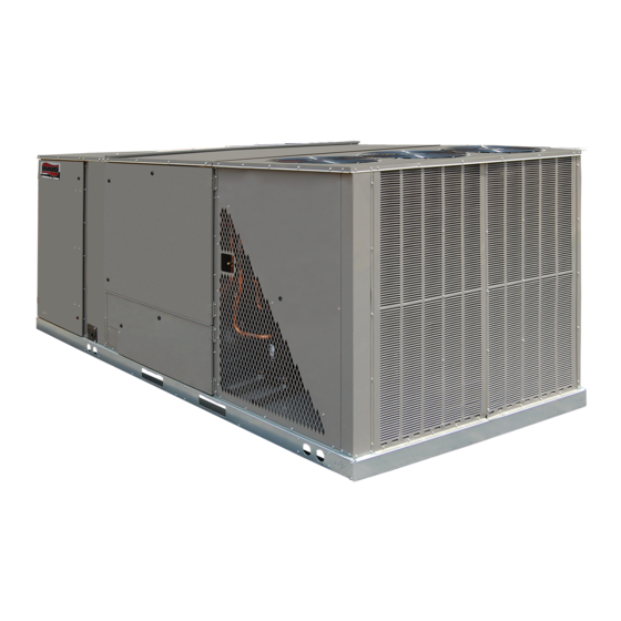
INSTALLATION INSTRUCTIONS
FOR THE RHEEM H
FEATURING eSYNC INTEGRATION TECHNOLOGY
RKHL-D SERIES 15 TON [52.8 kW]
ASHRAE 90.1 2007 COMPLIANT, WITH CLEAR CONTROL
INTEGR TION TECHNOLOGY
!
RECOGNIZE THIS SYMBOL AS AN INDICATION OF IMPORTANT SAFETY INFORMATION!
WARNING
!
THESE INSTRUCTIONS ARE INTENDED AS AN AID TO QUAL-
IFIED, LICENSED SERVICE PERSONNEL FOR PROPER
INSTALLATION, ADJUSTMENT AND OPERATION OF THIS
UNIT. READ THESE INSTRUCTIONS THOROUGHLY BEFORE
ATTEMPTING INSTALLATION OR OPERATION. FAILURE TO
FOLLOW THESE INSTRUCTIONS MAY RESULT IN IMPROPER
INSTALLATION, ADJUSTMENT, SERVICE OR MAINTENANCE
POSSIBLY RESULTING IN FIRE, ELECTRICAL SHOCK,
PROPERTY DAMAGE, PERSONAL INJURY OR DEATH.
PLEASE READ CAREFULLY AND KEEP IN A SAFE PLACE FOR FUTURE REFERENCE BY A SERVICEMAN
AC ROOFTOP UNIT
2
DO NOT DESTROY THIS MANUAL
[ ] INDICATES METRIC CONVERSIONS
92-23577-135-01
SUPERSEDES 92-23577-135-00
Advertisement
Table of Contents
Troubleshooting

Related Manuals for Rheem H2AC


Summary of Contents for Rheem H2AC
- Page 1 INSTALLATION INSTRUCTIONS FOR THE RHEEM H AC ROOFTOP UNIT FEATURING eSYNC INTEGRATION TECHNOLOGY RKHL-D SERIES 15 TON [52.8 kW] ASHRAE 90.1 2007 COMPLIANT, WITH CLEAR CONTROL INTEGR TION TECHNOLOGY RECOGNIZE THIS SYMBOL AS AN INDICATION OF IMPORTANT SAFETY INFORMATION! WARNING...
-
Page 2: Table Of Contents
TABLE OF CONTENTS I. SPECIFICATIONS ......... 3 General . -
Page 3: Specifications
Recognize this symbol as an indication of Important Safety Information! WARNING THE MANUFACTURER’S WARRANTY DOES NOT COVER ANY DAMAGE OR DEFECT TO THE AIR CONDITIONER CAUSED BY THE ATTACHMENT OR USE OF ANY COMPONENTS, ACCES- SORIES OR DEVICES (OTHER THAN THOSE AUTHORIZED BY THE MANU- FACTURER) INTO, ONTO OR IN CON- JUNCTION WITH THE AIR CONDI-... - Page 4 2. Quick Reference Guide For R-410A • R-410A refrigerant operates at approximately 60% higher pressure (1.6 times) than R- 22. Ensure that servicing equipment is designed to operate with R-410A. • R-410A refrigerant cylinders are pink. • R-410A, as with other HFC’s is only compatible with POE oils. •...
-
Page 5: Safety Information
SAFETY INFORMATION WARNING WARNING USE ONLY WITH TYPE OF GAS NEVER TEST FOR GAS LEAKS WITH AN OPEN FLAME. USE A COMMER- APPROVED FOR THIS UNIT. REFER CIALLY AVAILABLE SOAP SOLUTION MADE SPECIFICALLY FOR THE TO THE UNIT RATING PLATE. DETECTION OF LEAKS TO CHECK ALL CONNECTIONS, AS SPECIFIED IN GAS SUPPLY AND PIPING SECTION OF THESE INSTRUCTIONS. -
Page 6: Unit Dimensions
FIGURE 1 UNIT DIMENSIONS R CLEARANCES SEE PAGE 14, FIGURE 4. IMPORTANT: THIS UNIT MUST BE MOUNTED LEVEL IN BOTH DIRECTIONS TO ALLOW WATER TO DRAIN FROM THE CONDENSER SECTION AND CONDENSATE PAN. - Page 7 FIGURE 2 LEFT VIEW...
-
Page 8: General Data
Model RKHL- Series D180CL25E D180CL35E D180CM25E D180CM35E Cooling Performance GENERAL DATA - RKHL Continued -> NOM. SIZES 7.5-10 TON [26.4 & 35.2 kW] ENERGYSTAR COMPLIANT MODELS Gross Cooling Capacity Btu [kW] 182,000 [53.33] 182,000 [53.33] 182,000 [53.33] 182,000 [53.33] EER/SEER 12.4/NA 12.4/NA 12.4/NA... - Page 9 Model RKHL- Series D180DL25E D180DL35E D180DM25E D180DM35E Cooling Performance GENERAL DATA - RKHL NOM. SIZES 7.5-10 TON [26.4 & 35.2 kW] ENERGYSTAR COMPLIANT MODELS Gross Cooling Capacity Btu [kW] 182,000 [53.33] 182,000 [53.33] 182,000 [53.33] 182,000 [53.33] EER/SEER 12.4/NA 12.4/NA 12.4/NA 12.4/NA Nominal CFM/AHRI Rated CFM [L/s]...
-
Page 10: Gross Systems Performance Data
!"##$%&&'() *(##$%"!&!) +(##$%"",*) !"##$%&&'() *(##$%"!&!) +(##$%"",*) !"##$%&&'() *(##$%"!&!) +(##$%"",*) #-.* #-.. #-#! #-.* #-.. #-#! #-.* #-.. #-#! GROSS COOLING PERFORMANCE DATA – RKHL-D180 """$%,*-.) "."-!$%,"-&) "#,$%,#-+) ".#-!$%,.-!) "#.-'$%*'-") .'*-*$%*!-&) "#*-,$%,#-&) .'!$%*!-!) .'#-($%**-') .&!-!$%+#-+) ."&-($%&,-&) ..&-($%&&-&) .,"-($%+!-!) .+,-+$%+"-') .&+-,$%&'-+) .((-!$%**-&) .,'-,$%+'-!) .*,$%+*-!) Entering Indoor Air @ 80ºF [26.7ºC] dbE ! -
Page 12: Installation
II. INSTALLATION A. GENERAL 1. INSTALLATION — Install this unit in accordance with The American National Standard Z223.1-latest edition booklet entitled “National Fuel Gas Code,” and the requirements or codes of the local utility or other authority having jurisdiction. Additional helpful publications available from the “National Fire Protection Association”... -
Page 13: Exhaust & Combustion Hoods
2. In coastal areas locate the unit on the side of the building away from the waterfront. 3. Shielding by a fence or shrubs may give some protection. 4. Frequent washing of the cabinet, fan blade and coil with fresh water will remove most of the salt or other contaminants that build up on the unit. -
Page 14: Clearances
FIGURE 4 CLEARANCES Recommended Location Clearance in. [mm] 80 [2032] A - Front 18 [457] B - Condenser Coil 18 [457] C - Duct Side 18 [457]* D - Evaporator End 60 [1524] E - Above * Without Economizer 48 [1219] With Economizer ST-A1207-02 E. -
Page 15: Ducting
2. For rigging and roofcurb details, see Figures 6, 7 and 8. WARNING 3. The location of the unit on the roof should be such as to provide proper access for inspection and servicing. DO NOT, UNDER ANY CIRCUM- STANCES, CONNECT RETURN IMPORTANT: If unit will not be put into service immediately, block off supply and return DUCTWORK TO ANY OTHER air openings to prevent excessive condensation. -
Page 16: Return Air
H. RETURN AIR WARNING NEVER ALLOW PRODUCTS OF COMBUSTION OR THE FLUE PRODUCTS TO ENTER THE RETURN AIR DUCTWORK, OR THE CIRCULATING AIR SUP- PLY. ALL RETURN DUCTWORK MUST BE ADEQUATELY SEALED AND SECURED TO THE FURNACE WITH SHEET METAL SCREWS, AND JOINTS TAPED. -
Page 17: Gas Supply, Condensate Drain And Piping
III. GAS SUPPLY, CONDENSATE DRAIN AND III. PIPING A. GAS CONNECTION IMPORTANT: Connect this unit only to gas supplied by a commercial utility. 1. Install gas piping in accordance with local codes and regulations of the local utili- ty company. In the absence of local codes, the installation must conform to the specifications of the National Fuel Gas Code, ANSI Z223.1 - latest edition. -
Page 18: Lp Conversion
TO CHECK FOR GAS LEAKS, USE A SOAP AND WATER SOLUTION OR OTHER WARNING APPROVED METHOD. DO NOT USE AN OPEN FLAME. IMPORTANT: Check the rating plate to make certain the appliance is equipped to burn DO NOT USE AN OPEN FLAME TO the type of gas supplied. -
Page 19: Adjusting Or Checking Furnace Input
FIGURE 10B HONEYWELL VR8305Q4120 TWO STAGE GAS VALVE GAS INLET - 3/4“ [25.4] FNPT INLET PRESSURE TAP - 1/8 NPT ORDERING SPECIFICATION LABEL OUTLET PRESSURE TAP - 1/8 NPT 2-STAGE OPERATOR GROUND TERMINAL LOW STAGE ADJUSTMENT UNDER VENT CAP HIGH STAGE ADJUSTMENT WHEN INSTALLING THE GAS INLET PIPE, A BACKUP UNDER VENT CAP WRENCH MUST BE USED ON THE GAS VALVE TO... -
Page 20: Condensate Drain
Heating Value of Gas (BTU/Cu. Ft.) x 3600 Cu. Ft. Per Hr. Required = Time in Seconds (for 1 Cu. Ft.) of Gas Start the furnace and measure the time required to burn one cubic foot of gas. Prior to checking the furnace input, make certain that all other gas appliances are shut off, with the exception of pilot burners. - Page 21 the unit’s RATED VOLTAGE REQUIREMENT. Install a branch circuit disconnect near the rooftop, in accordance with the N.E.C., C.E.C. or local codes. 2. It is important that proper electrical power is available at the unit. Voltage should not vary more than 10% from that stamped on the unit nameplate. On three phase units, phases must be balanced within 3%.
-
Page 22: Hook-Up
Select the equivalent aluminum wire size from the tabulation below: Splice copper wire pigtails to aluminum wire with U.L. recognized connectors for copper- aluminum splices. Please exercise the following instructions very carefully to obtain a positive and lasting connection: 1. Strip insulation from aluminum conductor. 2. -
Page 23: Internal Wiring
between separate devices which are field installed and located, shall conform with the temperature limitation for Type T wire [63°F rise (35°C)] when installed in accor- dance with the manufacturer’s instructions. C. INTERNAL WIRING A diagram of the internal wiring of this unit is located on the inside of control access panel and in this manual. -
Page 24: System Pressure Test And Start Up
3. Use only solder, brazing, and pipe thread sealing materials approved for potable water systems. 4. Refer to connection diagram for typical piping, storage tank, and valve configurations. 5. It is highly recommended that the H AC rooftop unit be installed with isolation/flushing valves (see Figure 15, Webstone #40436 or similar) on the inlet and outlet water connections to facilitate required periodic lime and scale removal from the water-to-refrigerant heat exchanger. -
Page 26: Procedure For Calculating The Total Equivalent Length Of Tubing
EQUIVALENT LENGTH OF TUBING List all piping components from the storage tank to the H AC rooftop unit List all piping components from the storage tank to the hybrid unit and and back again. The equivalent length of straight tubing is the same as the back again. - Page 27 FIGURE 16 ISOLATION/FLUSHING VALVE Elbow Elbow Tee - Side Branch Tee - Straight Run PROCEDURE FOR CALCULATING THE TOTAL EQUIVALENT LENGTH OF TUBING elbow List all piping components from the storage tank to the H AC rooftop unit and back again.
- Page 28 !FG7H &@/2#"&1A(B"/2#&J$4&@/2#"&!"#$$%"#&'"()& %,"'# %&")# %("*# %*"(# %+"&# %)"$# %)"!# %'"%# %%")# %!"+# $"*# ,"&# E+K+L%L&D!E& &",# ("$# ("%# *"'# '#$+,K&D!E& +")# )"*# '"(# %"&# !"$# !"!# @/2#"&1A(B&C/2#&*D!E-&...
-
Page 29: H 2 Ac Rooftop Unit/Water Heater Sequence Of Operation
AC ROOFTOP UNIT SEQUENCE OF OPERATION FIGURE 17 ISOLATION/FLUSHING VALVE 1. On a call for cooling (“Y” from T’stat energized), unit always starts in air-cooled con- denser mode and runs for two minutes. NOTE: For this two-stage cooling and potable water heating unit, the water heating section is located on the rear (second stage) refrigerant system. -
Page 34: Furnace Section Controls And Ignition System
VI. FURNACE SECTION CONTROLS AND IGNITION SYSTEM NORMAL FURNACE OPERATING SEQUENCE This unit is equipped with a two stage integrated direct spark ignition control. NORMAL HEAT MODE A. Call For First Stage (low fire) Only: 1. Zone thermostat contacts close, a call for first stage (low fire) heat is initiated. 2. -
Page 35: Operating Instructions
E. First Stage and Second Stage Called Simultaneously: 1. Zone thermostat contacts close, a call for first stage (low fire) and second stage (high fire) heat is initiated. 2. Control runs self check. 3. Control checks the high-limit switch for normally closed contacts, each pressure switch for normally open contacts, and all flame rollout switches for continuity. -
Page 36: Burners
6. Wait five (5) minutes to clear out any gas. Then smell for gas, including near the floor. If you smell gas, STOP! Follow B in the safety information on the Operating Instructions located on the back of the controls/access panel. -
Page 37: Limit Control
LIMIT CONTROL The supply air high temperature limit cut-off is set at the factory and cannot be adjust- ed. It is calibrated to prevent the air temperature leaving the furnace from exceeding the maximum outlet air temperature. WARNING DO NOT JUMPER THIS DEVICE! DOING SO CAN CAUSE A FIRE OR EXPLO- SION RESULTING IN PROPERTY DAMAGE, PERSONAL INJURY OR DEATH. -
Page 38: Furnace Section Maintenance
3. Close doors and windows. This reduces the heating and cooling load on the sys- tem. 4. Avoid excessive use of exhaust fans. 5. Do not permit the heat generated by television, lamps or radios to influence the thermostat operation. 6. -
Page 39: Cooling Section Maintenance
LIME AND SCALE FLUSHING PROCEDURE Periodic flushing is required for the refrigerant-to-water heat exchanger contained in the Rheem H AC rooftop unit to remove lime and scale buildup and to prevent degradation of water heating performance. How often this is required depends on the... -
Page 40: Replacement Parts
• Small circulation pump • Hoses with connections suitable for the unit drain valves and pump. • 2-3 gallons of food-grade white vinegar. • The bucket, pump, and hoses can be ordered as Rheem flush kit RTG20124. FIGURE 19 Instructions: ISOLATION/FLUSHING VALVE 1. -
Page 41: Airflow Performance
X. AIRFLOW PERFORMANCE... -
Page 42: Electrical Data
ELECTRICAL DATA - RKHL- SERIES XI. ELECTRICAL DATA - RKHL D180CL D180CM D180DL D180DM Unit Operating Voltage Range 187-253 187-253 414-506 414-506 Volts 208/230 208/230 Minimum Circuit Ampacity 77/77 81/81 Minimum Overcurrent Protection Device 90/90 90/90 Size Maximum Overcurrent Protection Device 100/100 100/100 Size... -
Page 43: Troubleshooting Chart
XII. TROUBLESHOOTING FIGURE 20 COOLING TROUBLE SHOOTING CHART WARNING DISCONNECT ALL POWER TO UNIT BEFORE SERVICING. CONTACTOR MAY BREAK ONLY ONE SIDE. FAIL- URE TO SHUT OFF POWER CAN CAUSE ELECTRICAL SHOCK RESULTING IN PERSONAL INJURY OR DEATH. SYMPTOM POSSIBLE CAUSE REMEDY Unit will not run •... - Page 44 FIGURE 21 FURNACE TROUBLESHOOTING GUIDE (COMBINATION HEATING AND COOLING UNITS WITH DIRECT SPARK IGNITION) WARNING HAZARDOUS VOLTAGE DISCONNECT POWER BEFORE LINE VOLTAGE CON- SERVICING. NECTIONS SERVICE MUST BE BY A TRAINED, QUALIFIED SERVICE TECHNICIAN. START SET THERMOSTAT TO CALL FOR HEAT SET FAN SWITCH TO AUTO •...
- Page 45 NOTE: IF THE SYSTEM GOES INTO LOCKOUT, WAIT 30 SECONDS AND RESET THE SYSTEM. REPLACE SENSOR MAIN BURNER FLAME SUSTAINED • CHECK FLAME SENSOR POSITION AND CONDITION • CLEAN FLAME SENSOR WITH STEEL WOOL • CHECK FLAME SENSOR WIRES AND CONNECTIONS REPLACE IGNITION CON- TROL •...
-
Page 46: H 2 Ac Rooftop Unit Alarms And Troubleshooting
FIGURE 22 H AC ROOFTOP UNIT ALARMS AND TROUBLESHOOTING network or a er 24 hr lockout mer is reset. -
Page 47: Wiring Diagrams
XIII. WIRING DIAGRAMS FIGURE 23 RKHL SERIES... - Page 48 FIGURE 24 RKHL...
- Page 49 FIGURE 25 RKHL SERIES...
- Page 50 FIGURE 26 RKHL SERIES...
-
Page 51: Charge Charts
FIGURE 27 RKHL SYSTEM CHARGE CHARTS SYSTEM CHARGE CHART - REFRIGERANT 410A 15 TON, CIRCUITS 1 & 2 CAUTION: BOTH COMPRESSORS MUST BE OPERATING BEFORE CHECKING REFRIGERANT CHARGE. RETURN AIR TEMPERATURE MUST BE WITHIN COMFORT CONDITIONS BEFORE FINAL REFRIGERANT CHECK! MEASURE PRESSURE AT COMPRESSOR SUCTION AND DISCHARGE. - Page 52 CM 0117...