Advertisement
Quick Links
Use
C
CC1N7461en
21.08.2018
Burner Controls
The LFE1... burner control is designed for use with forced draft gas and dual-fuel
burners of any capacity, in intermittent operation.
The LFE1... and this Data Sheet are intended for use by OEMs which integrate the
burner controls in their products.
The LFE1... is designed for the fully automatic control and supervision of single-stage,
multi-stage or modulating gas or dual-fuel burners. It is suited for use with expanding
flame and interrupted pilot type gas burners. Flame supervision is ensured by means of
an ionization probe or a QRA... UV flame detector. Ignition spark proving with a UV
flame detector is also possible. When used in connection with a gas valve proving
system LDU11... (refer to Data Sheet N7696), the control sequence of the LFE1... can
be extended to include automatic gas valve proving. All types of burner controls comply
with the relevant European standards for gas and oil burners of any capacity.
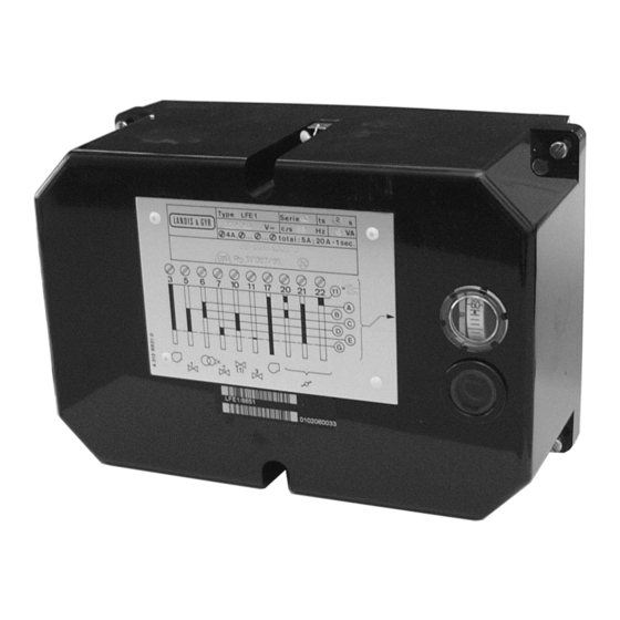
The LFE1... can control the following burner plant components:
fan motor, flue gas fan, air damper, ignition transformer, 1 to 3 fuel valves, load
controller and an external lockout warning device.
·
Applications in accordance with EN 676: Automatic forced draft burners for liquid
fuels
·
Type-tested in accordance with EN 298: 2004
Note!
Do not use for new designs.
7
LFE1...
Building Technologies
461
Advertisement

Related Manuals for Siemens LFE1 Series


Summary of Contents for Siemens LFE1 Series
- Page 1 Burner Controls LFE1... The LFE1... burner control is designed for use with forced draft gas and dual-fuel burners of any capacity, in intermittent operation. The LFE1... and this Data Sheet are intended for use by OEMs which integrate the burner controls in their products. The LFE1...
- Page 2 Use (cont´d) · Special features Prepurge time adjustable between 8 and 63 seconds · Operation optional with or without postpurging · Fully automatic control of the air damper, irrespective of the actuator running time · The air pressure check can be combined with the functional check of the air pressure switch prior to startup ·...
- Page 3 Installation notes · Always run the high ignition cables separate from the unit and other cables while observing the greatest possible distance · Install switches, fuses and earthing in compliance with local regulations · Make certain that the maximum permissible current rating of the connection terminals will not be exceeded ·...
- Page 4 ISO 14001:2015 OHSAS 18001:2007 China RoHS Hazardous substances table: http://www.siemens.com/download?A6V10883536 Lifecycle Burner controls has a designed lifetime* of 250,000 burner startup cycles which, under normal operating conditions in heating mode, correspond to 10 years of usage (starting from the production date given on the type field).
- Page 5 Mechanical design · LFE1... Plug-in design · The built-in unit fuse protects the control contacts of burner control against overloads · Impact-proof plastic housing · Able for optional mounting position at burner, on control panes or in control cabinets · Control unit driven by synchronous motor, the auxiliary relays, the electronic flame signal amplifier as soon as all the rest of switch, control and adjustable elements are build-on at stable PCBs and included in test circuit of burner control...
- Page 6 Type summary Article no. Type Mains voltage Factory settings for mains frequency BPZ:LFE1.1 / 8854 LFE1.1 / 8854 15 s BPZ:LFE1 / 8851 LFE1 / 8851 AC 220...240 V 60 s 50 Hz BPZ:LFE1 / 8853 LFE1 / 8853 BPZ:LFE1 / 8866 LFE1 / 8866 AC 100...110 V 30 s...
- Page 7 Technical data General unit data Mains frequency AC 220 V -15 %...AC 240 V +10 % LFE1... AC 100 V -15 %...AC 110 V +10 % Mains frequency 50...60 Hz ±6 % Unit fuse (built-in) T6,3H250V to DIN EN 60127, (5 x 20 mm) Primary fuse (external) Max.
- Page 8 Technical data (cont´d) There is no self-checking while measurements are made. Detector current measurement Ionization probe Flame detector QRA... LFE1... QRA... For detector currents, refer to «Technical data». Legend Electrolytic capacitor 100...470 µF; DC 10...25 V Ionization probe Microammeter Ri max. 5000 W 8/19 Building Technologies CC1N7461en...
- Page 9 Function Prerequisites for The burner can be started only when: burner startup the burner control’s sequence switch is in its start position the burner control has not locked out, e.g. caused by a defective UV tube the contacts of all control and safety devices in the control loop between terminals 8 and 9 are closed the air pressure switch does not indicate air pressure Defects in the flame supervision circuit or in the burner control itself prevent startup or...
- Page 10 Function (cont´d) Control sequence Controlled shutdown takes place as soon as one of the control or monitoring devices in following a controlled the control loop between terminals 8 and 9 opens its contacts. shutdown As a result, the fuel valves are immediately shut and the sequence switch is restarted to program postpurging, if scheduled.
-
Page 11: Basic Diagram
Basic diagram P (R) EK2* EK1* VIII VIII XIII QRA... (11) 7461a01/0207 (GV) N (Mp) When using UV flame detector QRA..., terminal 13 must be earthed. Attention! Do not press lockout reset button (EK...) for more than 10 seconds! Legend Load relay with contacts «ar...»... - Page 12 Sequence diagram of sequence switch TSA´ VIII XIII 7461a02/0901 Switching times (Factory settings: refer to «Type summary» and «ordering») LFE1... LFE1.1... 120 s 60 s Running time of sequence switch 8...63 s 4...31.5 s Prepurge time (adjustable) 0...9 s 0...4.5 s First safety time (adjustable, setting 0 s for ignition spark supervision) TSA´...
- Page 13 Setting facilities on the burner control · General notes Prior to making any settings, disconnect the burner control from the mains supply · Loosen all 6 retaining screws and remove the unit cover · The switching cam numbering starts from the motor ·...
- Page 14 Setting facilities on the burner control (cont´d) Setting the safety times The settings are made by means of the red cams of the sequence switch. Their time marks serve as adjustment guides. On completion of the settings, the securing screws of the cams should be tightened carefully to prevent inadvertent readjustments.
- Page 15 Connection examples and sequence diagrams Connection examples Actuator control by the LFE1... for expanding flame No load control. burners When using UV flame detector QRA..., terminal 13 must be connected to earth. LFE1 1 2 13 14 15 16 12 19 18 4 3 22 21 20 17 6 + LF P (R)
- Page 16 Connection examples for interrupted pilot burners On / off control with checked air damper operation. When using UV flame detector QRA..., terminal 13 must be connected to earth. LFE1 2 12 13 14 15 16 17 19 18 c1/c2 11 12 14 15 16 17 (GV) 100%...
- Page 17 Connection examples for interrupted pilot burners (cont´d) LFE... for firing on gas UV flame detectors can supervise both oil and gas flames, but gas flames can also be or oil, optional supervised with ionization probes. LFE1 (17) 1 2 12 13 15 14 16 3 19 4 8 18 9 I II III...
- Page 18 Connection examples for modulating burner control including checked air damper control Modulating burners designed for the continuous adjustment of the burner‘s output require a temperature or pressure control system, in addition to the standard burner control equipment, for example: Modulating controller RWF5 Temperature or pressure sensor with integrated setpoint adjuster Q...
- Page 19 To remove the unit cover, loosen the 2 screws B also. C: elongated holes for securing the base EK: lockout reset button SG: viewing window ã 2018 Siemens AG Building Technologies, Berliner Ring 23, D-76437 Rastatt Subject to change! 19/19 Building Technologies CC1N7461en 21.08.2018...