Advertisement
Quick Links
Use
CC1N7153en
21.09.2016
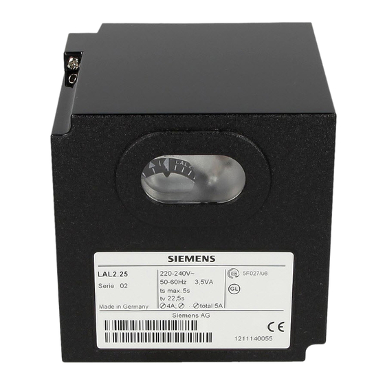
Oil Burner Controls
Oil burner controls
For oil atomizing burners of medium to large capacity
For multistage or modulating burners in intermittent operation
With or without air pressure supervision for checked air damper control
Flame supervision
– with photoresistive detector QRB
– or blue-flame detector QRC1
– or silicon photocell detector RAR9
Suitable for use with air heaters (WLE)
The LAL and this Data Sheet are intended for OEMs which integrate the oil
burner controls in their products!
For the control and supervision of oil atomization burners
For burners of medium to high capacity
For intermittent operation (at least one controlled shutdown every 24 hours)
Can be universally used with multistage or modulating burners
Suited for use with stationary air heaters (WLE)
The flame supervision is ensured via a Photoresistive detectors QRB,blue-flame
detectors QRC1 or Silicon photocell detectors RAR9.
LAL1
- Yellow- and blue-flame burners without air pressure supervision
LAL2
- Yellow-flame burners with air pressure supervision
LAL3.25
- For special applications, e.g. burners of incinerator plant
(for details, refer to «Type summary» and «Notes»)
Building Technologies Division
7
153
LAL...
Advertisement

Related Manuals for Siemens LAL Series


Summary of Contents for Siemens LAL Series
- Page 1 LAL... Oil Burner Controls Oil burner controls For oil atomizing burners of medium to large capacity For multistage or modulating burners in intermittent operation With or without air pressure supervision for checked air damper control Flame supervision –...
- Page 2 Supplementary documentation Product type Type of documentation Documentation number LOK16 (For burner controls used in Data Sheet N7785 connection with burners for continuous operation) Warning notes To avoid injury to persons, damage to property or the environment, the following warning notes must be observed! Do not open, interfere with or modify the unit! ...
- Page 3 Electrical connection of the flame detector It is important to achieve practically disturbance- and loss-free signal transmission: Never run the detector cable together with other cables – Line capacitance reduces the magnitude of the flame signal – Use a separate cable ...
- Page 4 Engineering notes (cont’d) Connect safety limit thermostats (manual reset) in the line (e.g. «SB») Remote reset When connecting lockout reset button «EK2» between terminals 21 and - terminal 3: For remote reset only - terminal 1: For remote reset and remote emergency shutdown ...
- Page 5 The electrical connections of the LAL and the AGM comply with the requirements of EN 60335-2-102. EAC Conformity mark (Eurasian Conformity mark) ISO 9001:2008 ISO 14001:2004 OHSAS 18001:2007 China RoHS Hazardous substances table: http://www.siemens.com/download?A6V10883536 Certified with plug-in base and flame detector: Type Only with QRB ● ● ● ●...
- Page 6 Life cycle Burner controls LAL has a designed lifetime* of 250,000 burner startup cycles which, under normal operating conditions in heating mode, correspond to approx. 10 years of usage (starting from the production date given on the type field). This lifetime is based on the endurance tests in the standard EN 298. A summary of the conditions has been published by the European Control Manufacturers Association (Afecor) (www.afecor.org).
- Page 7 Type summary The type references given below apply to the LAL without plug-in base and without flame detector. For ordering information for plug-in bases and other accessories, see Accessories. Switching times are given in the order of the startup sequence, valid for 50 Hz mains frequency. At 60 Hz frequency, switching times are about 17 % shorter. The type references apply to burner controls operating on AC 230 V, 50...60 Hz.
- Page 8 Accessories (to be ordered separately) Flame detectors Photoresistive detectors QRB See Data Sheet N7714 Blue-flame detectors QRC1 Frontal illumination: See Data Sheet N7716 Lateral illumination: Silicon photocell detectors RAR9 See Data Sheet N7713 Actuator SQN3 Actuators See Data Sheet N7808 Accessories for medium- Plug-in base AGM410490500 capacity burner controls...
- Page 9 Technical data General unit data LAL Mains voltage AC 230 V –15 / +10 % With LAL1 / LAL2 / LAL3 AC 100 V –15 %...AC 110 V +10 % Mains frequency 50...60 Hz ±6 % Unit fuse (built-in) T6.3H250V to DIN EN 60127 Primary fuse (external) Max.
- Page 10 Technical data (cont´d) Flame supervision LAL1 with LAL2 * / LAL3 * with QRC1 RAR9 Min. detector current required at AC 230 V 95 µA 80 µA 8 µA 6,5 µA Max. permissible detector current with no 12 µA 12 µA 0.8 µA 0.7 µA flame...
- Page 11 Function 2-stage expanding flame burner Legend BV... Fuel valve Flame signal amplifier Air damper Load controller M... Fan or burner motor t3´ Control thermostat or pressurestat Modulating fuel valve 100% Ignition transformer min. 0... Start command by «R» Operating position of burner 7153a09/0498 Burner operation Controlled shutdown...
- Page 12 Function (cont´d) Control of the burner Burner operation with or without postpurge Fan motors with a current draw of up to 4 A can be connected directly starting current max. 20 A (for max. 20 ms) Separate control outputs for –...
- Page 13 Startup sequence Start command by «R» «R» closes the start control loop between terminals 4 and 5 The sequence switch starts to run - Only prepurging, fan motor at terminal 6 receives power - Pre- and postpurging, fan motor or flue gas fan at terminal 7 receives power on completion of «t7» ...
- Page 14 Startup sequence (cont´d) Interval «BV1 – BV2» or «BV1 - LR» On completion of «t4», voltage is present at terminal 19 The voltage is required to power «BV2» connected to auxiliary switch «v» in the actuator Interval On completion of «t5», terminal 20 receives power.
- Page 15 Control sequence under fault conditions and lockout indication In case of any disturbance, the supply of fuel will immediately be interrupted. Whenever a fault occurs, the sequence switch stops and with it the lockout indicator. The symbol appearing above the reading mark indicates the type of fault: ...
- Page 16 Connection diagrams (for variants, refer to «Connection examples») LAL1 16 17 11 10 1(3) QRB... 7153a01/0814 QRC1... Note! In applications involving air heaters (WLE), or in the case of oil burners with a maximum throughput of > 30 kW/h, removing wire link B is not permitted. Caution! Do not press lockout reset button (EKx) for more than 10 seconds! 16/24...
- Page 17 Connection diagrams (for variants, refer to «Connection examples») (cont’d) LAL2 / LAL3 16 17 18 11 10 1(3) QRB... 7153a02/0814 RAR... Caution! Do not press lockout reset button (EKx) for more than 10 seconds! 17/24 Building Technologies Division CC1N7153en 21.09.2016...
- Page 18 Connection diagrams (for variants, refer to «Connection examples») LAL1 1 (3) LAL2 / LAL3 23 24 23 24 Warning! Do not press the lockout reset button «EKx» for more than 10 seconds! For the connection of the safety shutoff valve, refer to the plant diagram provided by the burner supplier.
- Page 19 Sequence diagram Control output at terminal: t3´ VIII t10* XIII 7153d01e/0404 Positions of lockout indication * These data do not apply to LAL1 19/24 Building Technologies Division CC1N7153en 21.09.2016...
- Page 20 Connection examples Connection of actuators without end «z» adjusted for low-fire air volume. switch for the «CLOSED» position 7153a11/0498 Control of actuator during operation For signal path, refer to «Connection by control signals fed to terminal 17 diagrams». 7153a12/0498 Control of «BVx» via terminal 20 Relay is not required if «BV3»...
-
Page 21: Open» And «Close
Connection examples and program sequence (cont’d) Load control with a 2-position controller. 2-stage expanding flame burner During burner off times, the air damper is closed. L... (t3´/t3n) (t3) 10 8 13 12 7153a05/1195 Control of actuator according to the single-wire control principle. - Page 22 Legend End switch for air damper’s OPEN position Remote lockout indicator (alarm) Main relay with «ar...» contacts Unit fuse Wire link (on the burner control’s base) Note! In applications involving air heaters (WLE), or in the case of oil burners with a maximum throughput of >...
- Page 23 Legend (cont’d) Lockout indication positions when there is no input signal (see Control sequence in the event of faults): ◄ No start ▲ Abortion of startup sequence ▼ Abortion of startup sequence ■ Lockout (fault in the flame supervision circuit) Lockout (no flame) Lockout (no air pressure) Time table...
- Page 24 Dimensions Dimensions in mm Plug-in base AGM410490500 / AGM13.1 7153m03/0305 27,5 27,5 2016 Siemens AG Building Technologies Division, Berliner Ring 23, D-76437 Rastatt Subject to change! 24/24 Building Technologies Division CC1N7153en 21.09.2016...