Advertisement
Table of Contents
- 1 Table of Contents
- 2 The LFL
- 3 Control Interface
- 4 Installation
- 5 Ordering Information
- 6 Wiring Base
- 7 Specifications
- 8 Specifications Continued
- 9 Description of Oper Controls
- 10 Ladder Diagram External Connections
- 11 Wiring Diagram
- 12 Sequence Dial OPERATION
- 13 Sequence Dial FAULT and LOCKOUT
- 14 Sequence Chart
- 15 Dimensions
- Download this manual
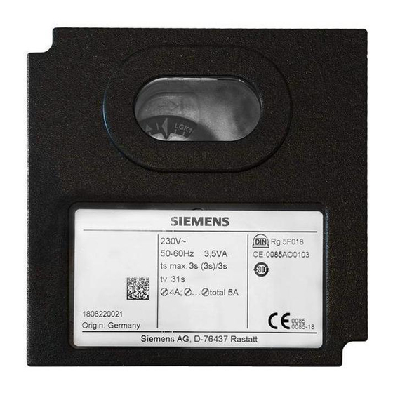
LFL
Series
Burner Flame Safeguard Control
The LFL... is a compact electro-mechanical
primary flame safeguard control designed to
provide burner sequencing, automatic igni-
tion and continuous flame monitoring for
gas, oil, and dual fuel, single burner applica-
tions.
The LFL... is applicable for on-off, multi-
designed for direct main burner ignition,
intermittent or interrupted pilot operation.
The LFL... integrates the flame amplifier,
purge timer and sequencer in a single con-
trol. Flame supervision is accomplished
using UV sensor or flame rod detection.
Features
• Primary flame safeguard control
• Visual sequence indication
• Optional combustion air blower control
• Optional postpurge
• Preignition interlock
• Continuous flame monitoring,
including extraneous light detection
• UV sensor functional test
• Proven air switch function
• Proven high fire purge interlock
• Proven low fire ignition interlock
• Direct main burner ignition,
intermittent or interrupted pilot operation
• Integrated flame amplifier
• UV sensor or flame rod detector
• Lockout alarm terminal
• Local and optional remote reset
• Burner off - economy position
(fully closed air damper interlock)
• Unit fuse and spare fuse provided
11.15.2004
Technical Instructions
Contents
Control Interface ................................................. 2
Installation........................................................... 2
Ordering information ........................................... 3
Wiring base......................................................... 3
Specifications ..................................................... 4
Specifications continued ..................................... 5
Description of oper controls ................................ 6
Ladder diagram external connections ................. 7
Sequence Dial OPERATION .............................. 8
Sequence Dial FAULT and LOCKOUT ............... 9
Sequence Chart ................................................ 10
Dimensions ....................................................... 11
Siemens Building Technologies
Document No. 7451US
LFL...
Rev. 2 November 15, 2004
HVAC Products
Advertisement
Table of Contents

Summary of Contents for Siemens LFL Series
-
Page 1: Table Of Contents
Sequence Dial FAULT and LOCKOUT ....9 • Local and optional remote reset Sequence Chart ..........10 • Burner off – economy position Dimensions ............11 (fully closed air damper interlock) • Unit fuse and spare fuse provided Siemens Building Technologies HVAC Products 11.15.2004... -
Page 2: The Lfl
Ground the LFL… wiring base. • Do not open or modify the LFL... • When UV flame supervision is used, other sources of radiation, such as halogen lamps, welding equipment, ignition sparks can produce erroneous flame signals. 2/12 Siemens Building Technologies HVAC Products 11.15.2004... -
Page 3: Ordering Information
Technical Instruction 7712 Flame rod By others Wiring Base The wiring base provides the following: • 24 Terminals ______________ • 3 Ground connections __________________-- • 3 Neutral connections, connected to terminal 2 3/12 Siemens Building Technologies CC1N7451en HVAC Products 11.15.2004... -
Page 4: Specifications
Environmental Operation temperature range -5...+140 °F < 95 % relative humidity ratings Storage temperature range -58...+140 °F < 95 % relative humidity Condensation, formation of ice and ingress of water are not permitted! 4/12 Siemens Building Technologies HVAC Products 11.15.2004... -
Page 5: Specifications Continued
• Multiple UV sensors QRA... and/or flame rods can be connected in parallel • If separate flame sensors are used for pilot and main flame supervision, an interrupted pilot must be utilized 5/12 Siemens Building Technologies CC1N7451en HVAC Products 11.15.2004... -
Page 6: Description Of Oper Controls
LFL output (20) RELEASE, enables an external load controlled and/or to indicate “Burner On“ Flame sensor input LFL inputs (22) (23) (24) FLAME can be used for a UV sensor or flame rod 6/12 Siemens Building Technologies HVAC Products 11.15.2004... -
Page 7: Ladder Diagram External Connections
Wiring Diagram 7/12 Siemens Building Technologies CC1N7451en HVAC Products 11.15.2004... -
Page 8: Sequence Dial Operation
Sequence dial – OPERATION 8/12 Siemens Building Technologies HVAC Products 11.15.2004... -
Page 9: Sequence Dial Fault And Lockout
Sequence dial – FAULT and LOCKOUT indication 9/12 Siemens Building Technologies CC1N7451en HVAC Products 11.15.2004... -
Page 10: Sequence Chart
COMBUSTION AIR BLOWER ACTUATOR FEEDBACK OPEN CLOSE (MINIMUM) ECONOMY (FULLY CLOSED) RELEASE TO MOD OPEN Modulation CLOSE (MINIMUM) ACTUATOR ECONOMY (FULLY CLOSED) MTFI POSTPURGE PTFI IDLE IGNITION PILOT MAIN (DIRECT IGNITION) MAIN (PILOTED) FLAME SIGNAL 10/12 Siemens Building Technologies HVAC Products 11.15.2004... -
Page 11: Dimensions
Dimensions Dimensions in inches Back Left Ø 5/16 (Ø 7.5 mm) Right Front Ø 3/4 3/16 x 1/4 (5.2 x 6.4 mm) 2 Places Ground Ø 3/16 Ø 4.4 mm) 11/12 Siemens Building Technologies CC1N7451en HVAC Products 11.15.2004... - Page 12 Dimensions QRA4.U Dimensions in inches 12/12 Siemens Building Technologies HVAC Products 11.15.2004...


