Table of Contents
Advertisement
ITS Solutions
5200 Northshore Dr.
North Little Rock, AR. 72118
501-687-0286
Dated 7/13/2020
University of Arkansas Animal Facility
700 Research Center Blvd.
Fayetteville, AR. 72701
Tag: AHU / CU
Liebert/Vertiv Closeout Documentation
• Liebert MiniMate User Manual (AHU)
• Liebert PFH Condenser User Manual (CU)
• Liebert Warranty
Advertisement
Table of Contents
Troubleshooting

Related Manuals for Emerson VERTIV Liebert Mini-Mate2 Series


Summary of Contents for Emerson VERTIV Liebert Mini-Mate2 Series
- Page 1 University of Arkansas Animal Facility 700 Research Center Blvd. Fayetteville, AR. 72701 Tag: AHU / CU Liebert/Vertiv Closeout Documentation • Liebert MiniMate User Manual (AHU) • Liebert PFH Condenser User Manual (CU) • Liebert Warranty ITS Solutions 5200 Northshore Dr. North Little Rock, AR.
- Page 2 Precision Cooling For Business-Critical Continuity™ Liebert Mini-Mate2 ® ™ User Manual - 1 & 1.5 Tons, 50 & 60Hz...
-
Page 4: Table Of Contents
TABLE OF CONTENTS —A ........1 ODEL UMBER OMENCLATURE... - Page 5 Outdoor Air-Cooled Condensing Unit Installation ....... . . 36 5.6.1 Location Considerations.
- Page 6 ........55 YSTEM ESTING AINTENANCE...
- Page 7 Figure 24 Piping and electrical connections ........... 37 Figure 25 Electrical field connections, 1- to 5-ton units .
-
Page 8: Model Number Nomenclature-All Systems
Model Number Nomenclature—All Systems —A ODEL UMBER OMENCLATURE YSTEMS Figure 1 Model number nomenclature—Self-contained, air-cooled units Liebert Mini-Mate2 D = Disconnect Switch 0 = No Disconnect Switch Nominal Capacity, kBtuh 12 & 18 (60Hz) — Unit Type A = Air-Cooled F = Air-Cooled with Free-Cooling Coil —... -
Page 9: Figure 2 Model Number Nomenclature-Split Evaporator Air-Cooled Units
Model Number Nomenclature—All Systems Figure 2 Model number nomenclature—Split evaporator air-cooled units Liebert Mini-Mate2 Humidification D = Disconnect Switch H = Canister Humidifier 0 = No Disconnect Switch 0 = No Humidifier Nominal Capacity, kBtuh R = Remote Humidifier Contact 12 &... -
Page 10: Figure 4 Model Number Nomenclature-Self-Contained, Water/Glycol-Cooled Units
Model Number Nomenclature—All Systems Figure 4 Model number nomenclature—Self-contained, water/glycol-cooled units Liebert Mini-Mate2 D = Disconnect Switch 0 = No Disconnect Switch Humidification Nominal Capacity, kBtuh H = Canister Humidifier 14 & 20 (60 Hz) 0 = No Humidifier R = Remote Humidifier Contact J = Canister Humidifier and Remote Unit Type Humidifier Contact... -
Page 11: Figure 5 Model Number Nomenclature-Chilled Water Units
Model Number Nomenclature—All Systems Figure 5 Model number nomenclature—Chilled water units Liebert Mini-Mate2 Humidification H = Canister Humidifier 0 = No Humidifier D = Disconnect Switch R = Remote Humidifier Contact 0 = No Disconnect Switch J = Canister Humidifier and Remote Nominal Capacity, kBtuh Humidifier Contact 23 (60Hz) -
Page 12: Important Safety Instructions
Important Safety Instructions MPORTANT AFETY NSTRUCTIONS SAVE THESE INSTRUCTIONS This manual contains important safety instructions that should be followed during the installation and maintenance of the Liebert Mini-Mate2. Read this manual thoroughly before attempting to install or operate this unit. Only qualified personnel should move, install or service this equipment. Adhere to all warnings, cautions and installation, operating and safety instructions on the unit and in this manual. - Page 13 Post a sign to alert people to report water flowing from the secondary drain pan. Emerson recommends installing monitored leak detection equipment for unit and supply lines and in the secondary drain pan.
-
Page 14: Introduction
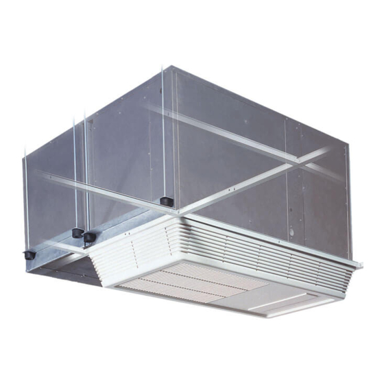
Introduction NTRODUCTION Designed to Match Computer and Electronic Equipment Needs—From Installation to Operation Installed above the ceiling, the Liebert Mini-Mate2 system controls the cooling, humidity and air distribution required by sensitive electronic equipment. A range of sizes and configurations are available to meet site needs. - Page 15 Introduction Location When determining installation locations, consider that these units contain water and that water leaks can cause damage to sensitive equipment and furniture below. NOTICE Risk of leaking water. Can cause equipment and building damage. Do not mount units over equipment or furniture that can be damaged by leaking water. Install a watertight drain pan with a drain connection beneath ducted cooling units and ceiling mounted water/glycol condenser units.
-
Page 16: Standard Features -1 & 1.5 Ton Systems
Standard Features—1 & 1.5 Ton Systems —1 & 1.5 T TANDARD EATURES YSTEMS Self-Contained Systems The self-contained system is designed for ceiling installation. The cabinet and chassis are constructed of heavy gauge galvanized steel. The unit can be serviced using only one side, increasing its versatility in mounting locations. -
Page 17: Other Standard Control Features
Standard Features—1 & 1.5 Ton Systems The wall-box is field-wired to the microprocessor control using standard four-conductor thermostat wire (field-supplied). The temperature and humidity sensors are in the wall box, which can be installed up to 300 feet (91.4m) from the evaporator unit. The unit-mounted control board also includes common alarm terminals and shutdown terminals. -
Page 18: Optional Factory -Installed Features -Self -Contained And Evaporator Units
Optional Factory-Installed Features—Self-Contained and Evaporator Units —S PTIONAL ACTORY NSTALLED EATURES ONTAINED AND VAPORATOR NITS Reheat Electric Reheat includes 304/304 stainless steel finned tubular reheat elements for added durability and corrosion resistance with a high limit safety switch. SCR Reheat provides tight temperature control by rapidly pulsing the 304/304 stainless steel reheat elements in small increments. -
Page 19: Free-Cooling
Optional Factory-Installed Features—Self-Contained and Evaporator Units Free-Cooling Free-cooling option includes separate cooling coil, three-way, slow-close valve and separate supply and return piping. Free-cooling is activated when the water temperature reaches a field-adjustable temperature, typically 45°F (7°C). The valve is rated for 300psi (2068kPa) working pressure. Air-cooled units can be specified with free-cooling coils, allowing chilled water to be the primary cooling and the air-cooled section to be the backup. -
Page 20: Ship -Loose Accessories -Field -Installed
Ship-Loose Accessories—Field-Installed —F OOSE CCESSORIES IELD NSTALLED Supply and Return Grille Kit includes supply and return grilles, 1" x 20" x 20" (25mm x 508mm x 508mm) MERV 8 rated filter to ASHRAE 52.2-2007, for installation into a 2ft. x 4ft. (610mm x 1220mm) ceiling grid. Duct Kit includes return air filter box with 1"... - Page 21 Liebert SiteScan is designed with flexibility for both small systems and large, complex systems such as those in computer rooms, telecommunications facilities or industrial process control rooms. Contact your local Emerson representative for assistance with a Liebert SiteScan system. ®...
-
Page 22: Site Preparation And Installation
Site Preparation and Installation REPARATION AND NSTALLATION NOTE Before installing unit, determine whether any building alterations are required to run piping, wiring and ductwork. Follow all unit dimensional drawings and refer to the submittal engineering dimensional drawings of individual units for proper clearances. Installation Considerations The evaporator unit is usually mounted above the suspended ceiling in the space to be conditioned. -
Page 23: Location Considerations
Site Preparation and Installation 5.1.2 Location Considerations NOTICE Risk of leaking water. Can cause equipment and building damage. Do not mount units over equipment or furniture that can be damaged by leaking water. Install a watertight drain pan with a drain connection beneath ducted cooling units and ceiling mounted water/glycol condenser units. -
Page 24: System Weights
Site Preparation and Installation Figure 9 Water/glycol-cooled systems, 1 and 1.5 tons Glycol-Cooled System, Ducted Glycol-Cooled System, Grille Water-Cooled Water-Cooled System, Grille System, Ducted Figure 10 Split system, air-cooled systems Split System, Grille Split System, Ducted System Weights Table 4 Unit weights Model # Weights, lb (kg) -
Page 25: Equipment Inspection (Upon Receipt)
If any damage is discovered when the unit is uncrated, report it to the shipper immediately. If any concealed damage is later discovered, report it to the shipper and to Emerson ® Installing Ceiling Units The evaporator unit is usually mounted above the ceiling and must be securely mounted to the roof structure. -
Page 26: Evaporator Air Distribution
Site Preparation and Installation 5.4.1 Evaporator Air Distribution Filter Box The optional filter box available for the unit attaches directly to the return air opening of the evaporator. The filter box is supplied with a filter measuring 16" x 20" x 1" (406 x 508 x 25mm). Grille Installation The airflow grilles are directional devices and MUST be installed with the louvers properly aligned for unit to operate properly. - Page 27 (2068kPa). Supply and return connection sizes are 5/8" (15.9mm) OD copper. Water/Glycol Loop Emerson recommends installing manual service shutoff valves at the supply and return line to each unit. This permits routine service and emergency isolation of the unit. Install 1/2" (13mm) diameter condensing fluid inlet and 1/2"...
- Page 28 Site Preparation and Installation Split System, Air-Cooled Model Refrigerant (R-407C) Loop All split systems require two refrigerant lines—an insulated copper suction line and a copper liquid line—between the evaporator and the outdoor condensing unit. The refrigerant lines can be piped by installing: •...
-
Page 29: Figure 11 Refrigerant Piping Diagram
Maximum recommended total equivalent pipe length is 150 ft (46m). Suction and liquid lines may require additional specialty items when vertical lines exceed 20 ft. (6m) and/or condensing unit installation is more than 15 ft. (4.6m) below the evaporator. Contact Emerson Application Engineering for assistance. ®... - Page 30 Site Preparation and Installation Table 7 Line charges—refrigerant per 100 ft. (30m) of Type L copper tube R-407C, lb/100 ft. (kg/30m) Line Size, O.D., in. Liquid Line Suction Line 3.7 (1.7) — 6.9 (3.1) — 11.0 (5.0 0.4 (0.2) 15.7 (7.1) 0.6 (0.3) 23.0 (10.4) 1.0 (0.4)
-
Page 31: Table 11 Refrigerant Charge In Liebert Pre-Charged R-407C Line Sets
Site Preparation and Installation Table 11 Refrigerant charge in Liebert pre-charged R-407C line sets Line Size, in. Length, ft. (m) Charge R-407C, oz (kg) 15 (4.5) 5 (0.14) 3/8 Liquid 30 (9) 10 (0.28) 15 (4.5) 5 (0.14) 5/8 Suction 30 (9) 10 (0.28) Refrigerant (R-407C) must be added to field refrigerant piping. -
Page 32: Figure 12 Dimensions-Air-Cooled, Self-Contained And Split Systems
Site Preparation and Installation Figure 12 Dimensions—Air-cooled, self-contained and split systems Threaded Rod Centers Left End 56"(1422mm) Threaded Rod Centers Condenser blower box location for Self-Contained, Air-Cooled Units See Figure 23 only. for dimensions. Removable Customer-supplied Access threaded rods for 3/8"... -
Page 33: Figure 13 Dimensions-Return Filter Box, All Systems
Site Preparation and Installation Figure 13 Dimensions—Return filter box, all systems 20-1/4" (514mm) 7-5/8" 8" (203mm) (194mm) 2-1/4" (57mm) 14" (357mm) 16" (406mm) 1-1/4" (32mm) 18" 3/4" (19mm) (457mm) Flange 1" Shaded area indicates a recommended (25.4mm) clearance of 30" (762mm) for component access and removal. -
Page 34: Figure 15 Unit Piping Data
Site Preparation and Installation Figure 15 Unit piping data Liquid Refrigerant Line Chilled Water Return 3/8" (9.5mm) Female Coupling Line (OUT) 5/8" (15.9mm) OD CU. Extends 3-1/2" (88.9mm) beyond panel exterior. Condenser Air Outlet for Self-Contained Air-Cooled Units. Suction Refrigerant Line 5/8"... -
Page 35: Figure 16 Unit Piping Data
Site Preparation and Installation Figure 16 Unit piping data 3-5/16" (84mm) 1-1/4" 2-5/16" (32mm) (59mm) 12-1/16" 2" 1-1/16" (306mm) (51mm) (27mm) 2" (51mm) 3-3/16" 1-3/8" (81mm) (35mm) 3-3/8" 9-7/8" (86mm) (251mm) 7-7/8" (200mm) 10" (254mm) 4-1/8" 3-3/4" (105mm) Detail "B" (95mm) 2-3/8"... -
Page 36: Condensate Pump Kit Installation
Site Preparation and Installation 5.4.3 Condensate Pump Kit Installation WARNING Risk of electric shock. Can cause injury or death. Disconnect all local and remote electric power supplies before working within the unit. Line side of factory disconnect remains energized when disconnect is Off. All Units 1. -
Page 37: Figure 18 General Arrangement Diagram - Split Systems With Air-Cooled Condensing Units
Site Preparation and Installation Figure 18 General arrangement diagram - split systems with air-cooled condensing units High Pressure Switch Compressor Condenser Coil External Filter Equalizer Drier Sensing Bulb Hot Gas Bypass Evaporator Solenoid Valve Coil Hot Gas Bypass Control Valve Expansion Valve DPN000168 Rev. -
Page 38: Figure 20 General Arrangement-Self-Contained Air-Cooled Unit With Hot Gas Reheat
Site Preparation and Installation Figure 20 General arrangement—Self-contained air-cooled unit with hot gas reheat Solenoid Valve Provided With High Optional Hot Pressure Gas Reheat Switch Check Valve Compressor Condenser Coil External Equalizer Filter Drier Sensing Coaxial condenser Bulb Hot Gas Bypass not shown Hot Gas Reheat Coil Solenoid Valve... -
Page 39: Electrical Connections
Site Preparation and Installation 5.4.4 Electrical Connections WARNING Arc flash and electric shock hazard. Open all local and remote electric power disconnect switches and wear protective equipment per NFPA 70E before working within the electric control enclosure. Failure to comply can cause injury or death. Unit contains hazardous voltage electric power. -
Page 40: Figure 22 Unit Electrical Connections
Field-supplied 24V Class 2 wiring to of a 2 wire, twisted pair, communication +5V, T-, T+ must be connected to Terminals TB1-1, TB1-2 and TB1-3. cable (available from Emerson or others) corresponding terminals on remote to optional Liebert SiteScan control wall box. -
Page 41: Centrifugal Condenser Fan Installation
Site Preparation and Installation Centrifugal Condenser Fan Installation The self-contained, air-cooled model utilizes a centrifugal blower in a housing that attaches directly to the right end of the ceiling unit. Mounting holes are pre-cut at the factory and fasteners are provided. In addition, a wiring harness is included for the power and control connections required from the ceiling unit to the blower. -
Page 42: Figure 23 Centrifugal Condenser Fan Dimensions And Installations
Site Preparation and Installation Figure 23 Centrifugal condenser fan dimensions and installations Step 2, 3 Remove These Screws First Item 2 Screw Only (Top) Item 1 Remove This Knockout Fasten Blower Harness Connection Here Item 2, 3 Do Not Remove Remove This Knockout Screw and Washer This Screw,... -
Page 43: Outdoor Air-Cooled Condensing Unit Installation
Site Preparation and Installation Outdoor Air-Cooled Condensing Unit Installation NOTE Follow all applicable national and local building, electrical and plumbing codes. 5.6.1 Location Considerations To insure a satisfactory air supply, locate air-cooled propeller fan condensing units in an environment providing clear air, away from loose dirt and foreign matter that may clog the coil. Condensing units must not be located in the vicinity of steam, hot air or fume exhausts or closer than 18 inches from a wall, obstruction or adjacent unit. -
Page 44: Figure 24 Piping And Electrical Connections
Site Preparation and Installation Figure 24 Piping and electrical connections Liquid Line Suction Line Quick Connect Quick Connect (Male Coupling) (Male Coupling) Electrical Entrance for High-Voltage Connection Electrical Entrance for Low-Voltage Connection DPN000132 Rev. 1 Table 15 Piping and electrical connections Model Numbers Electrical Connections, in. -
Page 45: Figure 25 Electrical Field Connections, 1- To 5-Ton Units
Site Preparation and Installation Figure 25 Electrical field connections, 1- to 5-ton units Field-supplied unit Field-supplied unit disconnect switch Single- or three-phase disconnect switch Single- or three-phase electric service not provided electric service not provided by Liebert by Liebert Field-supplied 24V Field-supplied 24V NEC Class 2 wiring NEC Class 2 wiring... -
Page 46: Checklist For Completed Installation
Site Preparation and Installation Checklist for Completed Installation ___ 1. Proper clearance for service access have been maintained around the equipment. ___ 2. Equipment is level and mounting fasteners are tight. ___ 3. Piping completed to refrigerant or coolant loop (if required). Refrigerant charge added (if required). -
Page 47: Microprocessor Control
Microprocessor Control ICROPROCESSOR ONTROL The Microprocessor Control for the Liebert Mini-Mate2 unit features an easy to use, menu-driven LCD. The menus, control features and circuit board details are described in this section. Detailed information concerning controls (7.0 - System Performance Microprocessor Controls) and alarms (8.0 - Alarms) are provided. -
Page 48: Setpoints
Microprocessor Control MAIN MENU <MENU> Press the MENU key to display the Main Menu. The menu selections, in order, include: • SETPOINTS • STATUS • ACTIVE ALARMS • TIME • DATE • SETBACK • SETUP OPERATION • SETPOINT PASSWORD • SETUP PASSWORD •... -
Page 49: Status
Microprocessor Control 6.1.2 Status The operator can monitor the percentage heating, cooling, dehumidifying and humidifying status of the unit by selecting the “STATUS” submenu. 6.1.3 Active Alarms The operator can monitor the alarms status by selecting “ALARMS” which will display a “No Alarm Present”... -
Page 50: Change Passwords
Microprocessor Control C/F Degrees The control may be selected to show readings and setpoints in either degrees Fahrenheit (F) or Celsius (C). To change the value, use Enter to select this function, then use the Up/Down Arrows to change the value. Press Enter to store the value. Humidity Control Method The operator may select either relative (direct) or absolute (predictive) humidity control. -
Page 51: Calibrate Sensors
Microprocessor Control 6.1.9 Calibrate Sensors The temperature and humidity sensor can be calibrated by selecting the CALIBRATE SENSORS menu item. The temperature sensor can be calibrated +5°F, while the humidity sensor can be calibrated ±10% RH. When calibrating the humidity sensor, the value shown will always be % RH, even though absolute humidity control may be selected. -
Page 52: 6.1.13 Custom Alarms
Microprocessor Control 6.1.13 Custom Alarms The custom alarm messages can be selected from a list of standard alarm messages, allowing the operator to write his/her own message. A MAXIMUM OF TWO (2) ALARM MESSAGES CAN BE CUSTOMIZED. The two custom alarm messages will initially display the previously programmed message but can be changed. -
Page 53: Run Diagnostics (Available On Rev 1.001.0)
Microprocessor Control Equipment Options Switches Equipment options are selected and enabled using DIP switches 1 through 7. These are located on the control board near TB1. These switches are factory-set and should not require any user changes. The setting and function of the switches can be individually read on the LCD.) NOTE In order to update the DIP switch settings, power must be cycled Off, then On, from the unit disconnect switch. - Page 54 Microprocessor Control Test Outputs When this feature is selected, the unit is effectively turned off. When stepping from one load to the next, the previous load is automatically turned off if it is on. The loads can also be toggled On and Off by selecting “ENTER”.
-
Page 55: Figure 27 Control Menu
Microprocessor Control Figure 27 Control menu Setup Password Setpoints / Setup Enter New PSW Temp Setpt Setup PSW = 000 Temp Sens Hum Setpt Hum Sens Calibrate Sensors Hi Temp Alm Temp Cal Lo Temp Alm Hum Cal Hi Hum Alm Temp Delay Lo Hum Alm Hum Delay... -
Page 56: Figure 28 Control Board (Inside Evaporator)
Microprocessor Control Figure 28 Control board (inside evaporator) 3 4 5 6 7 8 Table 22 Control board connections and functions Switch Function Switch Function TB2-4 Hot Gas Bypass TB1-2 Customer Alarm Connection #1 TB2-3 High Head Alarm Connection TB1-1 Customer Alarm Connection (Common) TB2-2 Heat Rejection (24VAC+) -
Page 57: Figure 29 Wall Box Board
Microprocessor Control Figure 29 Wall box board REV. TB3-1 TB3-2 TB3-3 TB3-4 Wall Box DIP Switches (1-8) ® ™ Liebert Mini-Mate2... -
Page 58: System Performance Microprocessor Controls
System Performance Microprocessor Controls YSTEM ERFORMANCE ICROPROCESSOR ONTROLS This section provides a detailed description of how the Liebert Mini-Mate2 responds to operator inputs and room conditions. Temperature Control 7.1.1 Cooling/Heating Required The temperature control program for the microprocessor is based on a calculated percentage requirement for cooling/heating. -
Page 59: Humidity Control
System Performance Microprocessor Controls Silicon Controlled Rectifier Electric Reheat (SCR) The SCR proportionally controls the stainless steel reheat feature to maintain the selected room temperature. The rapid cycling made possible by the SCR controller provides precise temperature control, while the constant element temperature improves heater life. During operation of the SCR control, THE COMPRESSOR OPERATES CONTINUOUSLY. -
Page 60: Alarms
11.0 - Troubleshooting for additional details. If you need further assistance, contact your Emerson supplier. THE CUSTOMER MUST SPECIFY ALARM(S) AT THE TIME OF ORDER. OTHER DEVICES AND WIRING MAY BE REQUIRED AT THE FACTORY FOR SOME OF THE ALARMS. -
Page 61: Humidity Level
Alarms 8.1.3 Humidity Level The humidity level alarm may be activated under the following conditions: High: The room return air humidity exceeds the pre-set high-humidity alarm setpoint. Is the unit set up for dehumidification? Check DIP switch. Low: The room return air humidity decreases to the high-humidity alarm setpoint. Is the unit setup for humidification? Check DIP switch. -
Page 62: System Testing And Maintenance
System Testing And Maintenance YSTEM ESTING AINTENANCE This section describes system testing, maintenance and replacement procedures. Use copies of the Maintenance Inspection Checklist on page 63 to record preventive maintenance inspections. WARNING Risk of electric shock. Can cause injury or death. Open all local and remote electrical power disconnect switches before working within the electrical enclosures. -
Page 63: Maintenance
System Testing And Maintenance Maintenance 9.2.1 Electric Panel The electric panel should be inspected on a semi-annual basis for any loose electrical connections. 9.2.2 Filters Experience shows that filters are usually the most neglected item in an environmental control system. In order to maintain efficient operation, they should be checked monthly and changed as required. - Page 64 System Testing And Maintenance Thermostatic Expansion Valve The thermostatic expansion valve keeps the evaporator supplied with enough refrigerant to satisfy load conditions. Proper valve operation can be determined by measuring superheat level. If too little refrigerant is being fed to the evaporator, then the superheat will be high. Conversely, if too much refrigerant is being supplied, then the superheat will be low.
-
Page 65: Figure 31 Hot Gas Bypass
System Testing And Maintenance compressor suction. The liquid quenching valve bulb senses this increased superheat and opens, allowing liquid refrigerant to mix with the discharge gas, desuperheating it. Proper mixing of the three refrigerant paths ensures stable operation and system performance. The liquid quenching valve bulb must be located down steam of all these connections to control superheat at the compressor inlet. -
Page 66: Replacement Procedures
(as required by the service contractor). If the compressor is under warranty, it must be returned to Emerson, in order to receive proper warranty credit. It should be returned in the same container it was shipped in. The possible cause(s) or condition(s) of the damage should be recorded on the provided return tag. -
Page 67: Steam Generating Humidifier-Operation Procedures
System Testing And Maintenance Replace a Failed Compressor Proper procedures to remove and replace the failed compressor are: 1. Disconnect power 2. Attach suction and discharge gauges to access fittings. 3. Recover refrigerant using standard recovery procedures and equipment. Use a filter-drier when charging the system with recovered refrigerant. - Page 68 System Testing And Maintenance 4. After a period of time, the mineral concentration in the canister becomes too high. When this occurs, the water boils too quickly. As the water quickly boils off and less of the electrode is exposed, the current flow decreases. When the current crosses the low threshold point (factory set at 85%) before the end of the time cycle, the drain valve opens, draining the mineral laden water out and replacing it with fresh water.
-
Page 69: Humidifier Circuit Board Adjustments
If adjustment is necessary and a change of three to four percent in either direction does not permit normal operation of the unit, consult your Emerson supplier. The POT1 controls the duration of the drain cycle. This adjustment is factory set at 60 seconds and should not be readjusted without consulting your Emerson supplier. -
Page 70: Maintenance Inspection Checklist
Maintenance Inspection Checklist 10.0 M AINTENANCE NSPECTION HECKLIST Make photocopies of this form for your records Date: Prepared By: Model #: Serial Number: NOTE Reheat element sheaths and fins are manufactured with stainless steel. Regular inspections are necessary to assure proper cleanliness of the reheating element. Should inspection reveal corrosion particles on the reheating element or adjoining surfaces (including ducts and plenums), appropriate cleaning should be performed. -
Page 71: Troubleshooting
Troubleshooting 11.0 T ROUBLESHOOTING WARNING Risk of electric shock. Can cause injury or death. Open all local and remote electrical power disconnect switches before working within electrical enclosures. Hazardous voltage will be present at evaporator, condenser, reheat and humidifier even with the unit turned Off at the control panel. - Page 72 Troubleshooting Table 26 Troubleshooting (continued) Symptom Possible Causes Check or Remedy DIP switch not set to enable See DIP switch settings Table 20. humidifier option “HUMIDIFY” not displayed at Increase humidity control setpoint and sensitivity to require control panel humidification. Check voltage at P3-1 and P1-9 on interface board for 24 VAC ±...
- Page 73 Power Switching & Controls Services DC Power Infrastructure Management & Monitoring Precision Cooling Surge Protection Emerson, Business-Critical Continuity, Emerson Network Power and the Emerson Network Power logo are trademarks of Emerson Electric Co. or one of its affiliated companies. ©2009 Emerson Electric Co.
- Page 74 Liebert® Prop Fan Condensing Unit™ 50 Hz and 60 Hz Installer/User Guide...
- Page 75 Technical Support Site If you encounter any installation or operational issues with your product, check the pertinent section of this manual to see if the issue can be resolved by following outlined procedures. Visit https://www.VertivCo.com/en-us/support/ for additional assistance.
- Page 76 TABLE OF CONTENTS 1 Product Description 1.1 Prop Fan Condensing Units 1.1.1 Base System 95°F (35°C) Ambient Models 1.1.2 105°F (41°C) Ambient Models 1.1.3 Liebert Quiet-Line™ Models 1.2 Optional Equipment 1.2.1 Coated Coil 1.2.2 Refrigerant Line Sweat Adapter Kit 1.2.3 277V Step-Down Transformer 2 Installation 2.1 Equipment Inspection 2.2 Location Considerations...
- Page 77 5 Troubleshooting Vertiv | Liebert PFH Installer/User Guide |...
- Page 78 1 PRODUCT DESCRIPTION Figure 1.1 Model number nomenclature 1.1 Prop Fan Condensing Units Liebert® propeller fan condensing units are available in a range of sizes and configurations to offer flexibility in designing a precision environmental control system. The appropriate propeller fan condensing unit paired with a corresponding Liebert fan coil evaporator model such as Liebert DataMate™, Liebert Mini-Mate2™...
- Page 79 1.2 Optional Equipment 1.2.1 Coated Coil This option provides a phenolic coating for the condenser coil (extended lead time is required for this option; consult factory). Pre-Charged Refrigeration Line Sets For efficient condenser/evaporator connection, factory pre-charged line sets with quick connect fittings are available in 15-ft.
- Page 80 2 INSTALLATION Read this entire installation section before starting installation. This section details dimensional, electrical and piping information and specifications that affect the placement of the PFH unit in relation the connected evaporator unit, other outside units, barriers and walls. Be particularly mindful of service and airflow clearances and maximum equivalent piping distances and in elevation differences between PFH and connected evaporator unit.
- Page 81 2.3 Dimensional Data Figure 2.1 Dimensions, horizontal air discharge Table 2.1 Cabinet and floor planning data, horizontal air discharge Net Weight Model Numbers Dimensional Data, in. (mm) lb. (kg) 60 Hz 50 Hz PFH014A-L — PFH020A-L — 40 (1016) 23-1/2 (597) 18 (457) 200 (91) PFH027A-L...
- Page 82 Figure 2.2 Dimensions, top air discharge Table 2.2 Electrical and piping connections, top air discharge Model Numbers Dimensional Data in. (mm) Module Net Weight, lb. (kg) 60Hz 50Hz PFH067A-H PFH066A-H 488 (222) PFHZ67A-L PFHZ66A-L 53 (1343) 36-1/4 (918) 38-1/2 (978) 5-1/2 (140) PFH096A-L PFH095A-L...
- Page 83 Figure 2.3 Dimensional data, 277V step-down transformer Vertiv | Liebert PFH Installer/User Guide |...
- Page 84 2.4 Piping and Electrical Connections Figure 2.4 Piping and electrical connections, horizontal discharge Table 2.3 Electrical and piping connections, horizontal air discharge Model Numbers Electrical Connections, in (mm) Piping Connections, in. (mm) 60Hz 50Hz PFH014A-L — PFH020A-L — 2-1/4 (57) 5-1/4 (133) 7-3/4 (197) 8-3/4 (222)
- Page 85 Figure 2.5 Piping and electrical connections, top air discharge Table 2.4 Piping and electrical connections, top air discharge Electrical Connections Piping Connections Model Numbers in. (mm) in. (mm) 60Hz 50Hz PFH067A- H PFH066A-H — 8-1/2 4-3/4 7-3/4 8-1/2 PFHZ67A- L PFHZ66A-L —...
- Page 86 Figure 2.6 General piping arrangement Vertiv | Liebert PFH Installer/User Guide |...
- Page 87 Figure 2.7 Electrical field connections, 1- to 5-ton units Vertiv | Liebert PFH Installer/User Guide |...
- Page 88 Figure 2.8 Electrical field connections, 8-ton units Vertiv | Liebert PFH Installer/User Guide |...
- Page 89 Figure 2.9 Single-phase, 1-3 ton model schematic, typical Vertiv | Liebert PFH Installer/User Guide |...
- Page 90 Figure 2.10 Three-phase, 3-5 ton model schematic, typical Vertiv | Liebert PFH Installer/User Guide |...
- Page 91 Figure 2.11 Three-phase, 8 ton model schematic, typical 2.5 Piping Considerations The Liebert® Mini-Mate2™, Liebert DataMate™ and the 3-ton Liebert Challenger 3000™ split system units are designed with quick-connect fittings and are factory-charged to proper refrigerant levels. This permits connecting units without brazing inside critical spaces. These split systems require two refrigerant lines—an insulated copper suction line and a copper liquid line—between the evaporator and condensing units.
- Page 92 • Using optional pre-charged line sets (for 1- to 3.5-ton R-407C model units only). • Using optional Sweat Adapter Kit(s) and hard piping between units. NOTICE Risk of improper handling of refrigerant. Can cause environmental damage and violation of environmental regulations.
- Page 93 Figure 2.12 Refrigerant piping diagram Table 2.5 Pipe length and condenser elevation relative to evaporator Nominal Max. Equiv. Maximum PFH Maximum PFH Level System Size Pipe Length Level Above Below Evaporator, ft. Tons ft. (m) Evaporator, ft. (m) 1, 1.5, 2 150 (45) 40 (12) 15 (4.6)
- Page 94 Table 2.6 Equivalent lengths for various pipe fittings, ft (m) Copper Pipe 90 Degree 90 Degree 45 Degree Gate Globe Angle OD, in. Elbow Copper Elbow Cast Elbow Valve Valve Valve 0.8 (0.24) 1.3 (0.39) 0.4 (0.12) 2.5 (0.76) 0.26 (0.07) 7.0 (2.13) 4.0 (1.21) 0.9 (0.27)
- Page 95 Prevailing good refrigeration practices should be employed for piping supports, leak testing, evacuation, dehydration and charging of the refrigeration circuits. The refrigeration piping should be isolated from the building by the use of vibration-isolating supports. Use a soft, flexible material to pack around the tubes when sealing openings in walls to prevent tube damage and to reduce vibration transmission.
- Page 96 Table 2.9 Recommended line sizes, OD Cu PFH_36A PFH_67A PFH_37A PFH_42A PFH_66A PFH_14A PFH_20A PFH_27A Equiv. 3-ton circuit PFH_41A 5-ton circuit ft. (m) of 8-ton model of 8-ton model Suction Liquid Suction Liquid Suction Liquid Suction Liquid Suction Liquid Suction Liquid 5/8"...
- Page 97 Table 2.10 Piping connection sizes and torque Line Size, OD Cu Coupling Size Torque, lb-ft. (N-m) 1/4 or 3/8 10-12 (145-175) 5/8 thru 7/8 #10 or #11 35-45 (510-655) 1-1/8 50-65 (730-950) Table 2.11 Line charges - refrigerant per 100 ft. (30m) of Type L copper tube R-407C, lb/100 ft.
- Page 98 Filter Drier Selection and Installation Recommended Install a replaceable-core filter drier approved for POE oil. The existing drier must be removed. The replaceable core drier will not fit in the same location as the existing drier. 2. Ensure there is enough clearance for replacing cores when choosing a location. 3.
- Page 99 Table 2.12 Evaporator Charge Levels Evaporator Charge R-407C Indoor Unit Models oz (kg) MMD12E 3 (0.085) MMD18E 4 (0.113) MMD24E 7 (0.198) Liebert Mini-Mate2™ MMD35/36E 7 (0.198) MMD59/60E 4 (0.113) MMD95/96E 7 (0.198) each circuit DME020E 4 (0.113) Liebert DataMate™ DME027E 5 (0.141) DME037E...
- Page 100 Table 2.13 Design refrigerant pressures 53 - 95 PSIG Suction (365 to 655 kPa) Discharge 280 psig (1930 kPa) (At Design Ambient) High-Pressure Cutout 400 psig (2760 kPa) Table 2.14 Application limits Input voltage Dry Bulb Air Temperature at Condenser Minimum Maximum Minimum...
- Page 101 2.7 Electrical Data Table 2.16 Electrical data—Standard sound and ambient models (95°F/35°C) 60Hz Nominal Input Voltage- Phase * Electrical Model # Capacity Characteristic 208/230-1 208/230-3 460-3 575-3 Tons — — — 11.0 — — — — — — 12.1 — —...
- Page 102 Table 2.17 Electrical data—High ambient models (105°F/41°C) 60Hz Nominal Input Voltage-Phase * Electrical Model # Capacity, Characteristic 208/230-1 208/230-3 460-3 575-3 Tons 15.4 — — — 18.4 — — — — — — 20.5 15.4 24.8 18.4 — 17.0 — 20.4 —...
- Page 103 Table 2.19 Electrical data—Standard sound and ambient models (95°F/35°C) 50Hz Nominal Input Voltage-Phase * Electrical Model # Capacity Characteristic 220-1 380/415-3 Tons 18.4 — — 11.7 — 18.1 * FLA = Full Load Amps Table 2.20 Electrical data—High ambient models (105°F/41°C) 50Hz Nominal Input Voltage-Phase...
- Page 104 5. All piping connections are tight. 6. Piping routed to prevent chafing and rub-through. 7. Piping has been evacuated and refrigerant charge added (if required). 8. Line voltage to power wiring matches equipment nameplate. 9. Power wiring connections completed, including earth ground. 10.
- Page 105 This page intentionally left blank. Vertiv | Liebert PFH Installer/User Guide |...
- Page 106 3 OPERATION 3.1 Compressor The scroll compressor is equipped with a band type crankcase heater to resist liquid refrigerant migration into the compressor during the Off cycle. The three-phase scroll compressor requires proper phasing to ensure correct motor rotation. The component connections have been phase synchronized at the factory. Refer to Electrical Connections on page 22 to verify proper compressor wiring.
- Page 107 A temperature-compensated heater maintains the liquid refrigerant pressure during Off cycles. A liquid pressure switch is also installed to turn the heater Off during operation, when the receiver pressure is high. The heater pressure switch has a cutout of 150psig (1034kPa) and a cut-in of 100psig (690kPa). The receiver includes a pressure relief valve set for 475psig (3275kPa).
- Page 108 7. There may be a variation of approximately 3 to 6psig (21 to 41kPa) on the evaporator due to the differential on the hot gas bypass. 8. Return temperature setpoint to the desired setting. Vertiv | Liebert PFH Installer/User Guide |...
- Page 109 This page intentionally left blank. Vertiv | Liebert PFH Installer/User Guide |...
- Page 110 4 MAINTENANCE 4.1 General Access the condensing unit by removing the unit housing panel. Clean the air cooled condenser coil of all debris that will inhibit airflow. This can be done with compressed air or with a commercial coil cleaner. Check for bent or damaged coil fins and repair as necessary.
- Page 111 NOTE: Failure to properly clean the system after a compressor motor burnout will void the compressor warranty. Follow the manufacturer’s procedure. NOTICE Risk of contact with caustic substances. Can cause personal injury. Avoid touching or contacting the gas and oils with exposed skin. Severe burns may result. Use long rubber gloves in handling contaminated parts.
- Page 112 4.4 Field Charge Verification An integral sight glass is provided with the receiver to assist in field charge verification. During charge verification set the control temperature down to keep the system running. If the system is equipped with hot gas bypass, de-energize it by removing power from the hot gas solenoid valve coil. To remove power, disconnect the solenoid leads from the unit contactor in the electric box (refer to the specific unit schematic;...
- Page 113 Table 4.1 Field verification charge Model Numbers R-407C 60Hz 50Hz oz (kg) PFH014A-_L — PFH020A-_L — 4 (0.11) PFH027A-_L — PFH027A-_H — PFHZ27A-_L — 18 (0.51) PFH037A-_L PFH036A-_L PFH042A-_L PFH041A-_L PFH037A-_H PFH036A-_H PFHZ37A-_L PFHZ36A-_L 8 (0.23) PFH042A-_H PFH041A-_H PFHZ42A-_L PFHZ41A-_L PFH067A-_L PFH066A-_L 18 (0.51)
- Page 114 5 TROUBLESHOOTING Table 5.1 Troubleshooting Problem Cause Remedy No power to unit Check voltage at input terminal block. Check for 24VAC ±2VAC at control connections 1 & 2. If no voltage, check control setting requires cooling. If there is voltage, lockout relay Compressor contactor not pulling in may be energized.
- Page 115 Table 5.1 Troubleshooting (continued) Problem Cause Remedy Low line voltage Check line voltage and determine location of voltage drop. Compressor cycles on locked Compressor motor defective Check for motor winding short or ground. rotor Single phasing Check voltage across all 3 legs at contactor. Correct source of problem. Check control panel for welded Motor burnout contactor contacts or welded overload...
- Page 117 VertivCo.com | Vertiv Headquarters, 1050 Dearborn Drive, Columbus, OH, 43085, USA © 2017 Vertiv Co. All rights reserved. Vertiv and the Vertiv logo are trademarks or registered trademarks of Vertiv Co. All other names and logos referred to are trade names, trademarks or registered trademarks of their respective owners. While every precaution has been taken to ensure accuracy and completeness herein, Vertiv Co.