Sign In
Upload
Manuals
Brands
Emerson Manuals
Air Conditioner
PFHZ41A-L
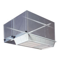
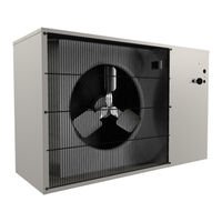
Emerson PFHZ41A-L Fan Condensing Unit Manuals
Manuals and User Guides for Emerson PFHZ41A-L Fan Condensing Unit. We have
2
Emerson PFHZ41A-L Fan Condensing Unit manuals available for free PDF download: User Manual, Installation, Operation And Maintenance Manual
Emerson PFHZ41A-L User Manual (117 pages)
Brand:
Emerson
| Category:
Air Conditioner
| Size: 6.15 MB
Table of Contents
Table of Contents
4
Model Number Nomenclature-All Systems
8
Figure 2 Model Number Nomenclature-Split Evaporator Air-Cooled Units
9
Figure 3 Model Number Nomenclature-Outdoor Air-Cooled Prop Fan Condensing Units
9
Figure 4 Model Number Nomenclature-Self-Contained, Water/Glycol-Cooled Units
10
Figure 5 Model Number Nomenclature-Chilled Water Units
11
Figure 1 Model Number Nomenclature-Self-Contained, Air-Cooled Units
8
Important Safety Instructions
12
Save These Instructions
12
1 Introduction
14
Designed to Match Computer and Electronic Equipment Needs-From Installation to Oper- Ation7
14
2 Standard Features -1 & 1.5 Ton Systems
16
Self-Contained Systems
16
Air-Cooled Unit
16
Water/Glycol-Cooled Unit
16
Chilled Water Unit
16
Evaporator Section-Split Systems
16
Condensing Unit Section-Split System
16
System Controls
16
Other Standard Control Features
17
Figure 6 Wall-Mounted Display Box
17
3 Optional Factory -Installed Features -Self -Contained and Evaporator Units
18
Reheat
18
Humidifier
18
Sensors
18
Switches
18
Free-Cooling
19
Optional Configuration-Prop Fan Condensing Units
19
Optional Configurations-Water/Glycol-Cooled Units
19
Optional Configuration-Chilled Water Units
19
Figure 7 Free Cooling Option-Example
19
4 Ship -Loose Accessories -Field -Installed
20
Remote Monitoring, Autochangeover and Leak Detection Equipment
20
5 Site Preparation and Installation
22
Installation Considerations
22
Room Preparation
22
Table 1 Table
22
Table 5 Table
22
Location Considerations
23
Figure 8 Air-Cooled Systems, 1 and 1.5 Tons
23
System Weights
24
Figure 9 Water/Glycol-Cooled Systems, 1 and 1.5 Tons
24
Figure 10 Split System, Air-Cooled Systems
24
Table 4 Unit Weights
24
Equipment Inspection (Upon Receipt)
25
Installing Ceiling Units
25
Evaporator Air Distribution
26
Piping Connections and Coolant Requirements
26
Figure 11 Refrigerant Piping Diagram
29
Table 7 Table
29
Table 9 Table
29
Table 11 Refrigerant Charge in Liebert Pre-Charged R-407C Line Sets
31
Figure 12 Dimensions-Air-Cooled, Self-Contained and Split Systems
32
Figure 13 Dimensions-Return Filter Box, All Systems
33
Figure 14 Dimensions-Supply/Return Grille Kit, All Systems
33
Figure 15 Unit Piping Data
34
Figure 16 Unit Piping Data
35
Condensate Pump Kit Installation
36
Figure 17 Condensate Pump
36
Figure 18 General Arrangement Diagram - Split Systems with Air-Cooled Condensing Units
37
Figure 19 Free-Cooling Coil Arrangement, Air-Cooled Units
37
Figure 20 General Arrangement-Self-Contained Air-Cooled Unit with Hot Gas Reheat
38
Figure 21 General Arrangement-Split Systems with Air-Cooled Condensing Units
38
Electrical Connections
39
Figure 22 Unit Electrical Connections
40
Centrifugal Condenser Fan Installation
41
Electrical, Control and Power Connections
41
Indoor Condenser Fan Ductwork
41
Figure 23 Centrifugal Condenser Fan Dimensions and Installations
42
Outdoor Air-Cooled Condensing Unit Installation
43
Location Considerations
43
Piping Connections
43
Electrical Connections
43
Table 13 Unit Dimensions
43
Table 14 Recommended Minimum Wire Size
43
Figure 24 Piping and Electrical Connections
44
Figure 25 Electrical Field Connections, 1- to 5-Ton Units
45
Checklist for Completed Installation
46
6 Microprocessor Control
47
Feature Overview
47
Figure 26 Microprocessor Control Layout
47
Setpoints
48
Table 16 View Default Setpoints and Allowable Ranges
48
Active Alarms
49
Date
49
Setback
49
Setup Operation
49
Status
49
Table 17 Logging a Setback Plan
49
Time
49
Change Passwords
50
Table 18 Setup Functions, Default Values and Allowable Ranges
50
6.1.10 Alarm Enable
51
6.1.11 Alarm Time Delay
51
6.1.12 Common Alarm Enable
51
Calibrate Sensors
51
Table 19 Alarm Default Time Delays
51
6.1.13 Custom Alarms
52
6.1.14 Custom Text
52
Run Diagnostics (Available on Rev 1.001.0)
53
Figure 27 Control Menu
55
Figure 28 Control Board (Inside Evaporator)
56
Table 22 Control Board Connections and Functions
56
Figure 29 Wall Box Board
57
7 System Performance Microprocessor Controls
58
Temperature Control
58
Cooling/Heating Required
58
Cooling Operation (Cooling, Compressorized Direct Expansion and Chilled Water)
58
Heating Operation
58
Figure 30 Ground Current Detector
58
Table 23 Cooling and Dehumidification Load Response of Hot Gas Bypass
58
Humidity Control
59
Dehumidification/Humidification Required
59
Dehumidification Operation, Compressorized Direct Expansion (DX) Systems
59
Humidification Operation
59
Load Control Features
59
Communication
59
8 Alarms
60
Alarms: Definitions and Troubleshooting
60
Custom Alarms
60
High Head Pressure
60
Humidity Level
61
Temperature
61
Humidifier Problem Alarm
61
High-Water Alarm
61
Loss of Power
61
Short Cycle
61
Optional/Custom Alarms
61
Loss of Water Flow
61
Smoke Detected
61
9 System Testing and Maintenance
62
System Testing
62
Environmental Control Functions
62
Cooling
62
Heating
62
Humidification
62
Dehumidification
62
High-Temperature Sensor-Optional
62
Smoke Sensor
62
Remote Shutdown
62
Maintenance
63
Electric Panel
63
Filters
63
Direct Drive Blower Package
63
Refrigeration System
63
Table 24 Typical Discharge Pressure
63
Figure 31 Hot Gas Bypass
65
Replacement Procedures
66
Compressor Replacement
66
Electrical Failure
66
Steam Generating Humidifier-Operation Procedures
67
Humidifier Circuit Board Adjustments
69
Table 25 DIP Switch Settings for Humidifier Control Board
69
10 Maintenance Inspection Checklist
70
11 Troubleshooting
71
Advertisement
Emerson PFHZ41A-L Installation, Operation And Maintenance Manual (36 pages)
Liebert Prop Fan Condensing Unit
Brand:
Emerson
| Category:
Air Conditioner
| Size: 0.91 MB
Table of Contents
Table of Contents
3
1 Product Description
5
Prop Fan Condensing Units
5
Base System 95°F (35°C) Ambient Models
5
105°F (41°C) Ambient Models
5
Quiet-Line Models
5
Optional Equipment
5
Coated Coil
5
Pre-Charged Refrigeration Line Sets
5
Refrigerant Line Sweat Adapter Kit
5
277V Step-Down Transformer
5
2 Installation
6
Equipment Inspection
6
Location Considerations
6
Dimensional Data
7
Figure 1 Dimensions, Horizontal Air Discharge
7
Table 1 Cabinet and Floor Planning Data, Horizontal Air Discharge
7
Figure 2 Dimensions, Top Air Discharge
8
Table 2 Electrical and Piping Connections, Top Air Discharge
8
Figure 3 Dimensional Data, 277V Step-Down Transformer
9
Piping and Electrical Connections
10
Figure 4 Piping and Electrical Connections, Horizontal Discharge
10
Table 3 Electrical and Piping Connections, Horizontal Air Discharge
10
Figure 5 Piping and Electrical Connections, Top Air Discharge
11
Table 4 Piping and Electrical Connections, Top Air Discharge
11
Figure 6 General Piping Arrangement
12
Figure 7 Electrical Field Connections, 1- to 5-Ton Units
13
Figure 8 Electrical Field Connections, 8-Ton Units
14
Figure 9 Single-Phase, 1-3 Ton Model Schematic, Typical
15
Figure 10 Three-Phase, 3-5 Ton Model Schematic, Typical
16
Figure 11 Three-Phase, 8 Ton Model Schematic, Typical
17
Piping Considerations
18
Piping for Elevation Differences between PFH and Evaporator
18
Figure 12 Refrigerant Piping Diagram
19
Table 5 Pipe Length and Condenser Elevation Relative to Evaporator
19
Table 6 Equivalent Lengths for Various Pipe Fittings, Ft (M)
19
Pre-Charged Line Sets
20
Field-Fabricated Line Sets
20
Table 7 Refrigerant Charge in Liebert Pre-Charged R-407C Line Sets
20
Table 8 Liebert PFH Unit Charge Levels and Coupling Size
21
Table 9 Recommended Line Sizes, OD Cu
21
Installation of Piping to Units
22
R-407C PFH Installed as a Replacement Condensing Unit in an R-22 System
22
Table 10 Piping Connection Sizes and Torque
22
Table 11 Line Charges - Refrigerant Per 100 Ft. (30M) of Type L Copper Tube
22
General System Charge Requirements
24
Table 12 Evaporator Charge Levels
24
Electrical Connections
25
Low-Voltage Control Wire Connections
25
Low-Voltage Control Wire Sizing
25
Table 13 Design Refrigerant Pressures
25
Table 14 Application Limits
25
Table 15 Recommended Minimum Wire Size
25
Electrical Data
26
Table 16 Electrical Data-Standard Sound and Ambient Models (95°F/35°C) 60Hz
26
Table 17 Electrical Data-High Ambient Models (105°F/41°C) 60Hz
26
Table 18 Electrical Data-Quiet-Line Models (95°F/35°C) 60Hz
27
Table 19 Electrical Data-Standard Sound and Ambient Models (95°F/35°C) 50Hz
27
Table 20 Electrical Data-High Ambient Models (105°F/41°C) 50Hz
27
Checklist for Completed Installation
28
Table 21 Electrical Data - Quiet-Line Models (95°F/35°C) 50Hz
28
3 Operation
29
Compressor
29
High Head Pressure
29
Liebert Lee-Temp Flood Back Head Pressure Control
29
Hot Gas Bypass
30
Operation
30
Adjustment
30
Figure 13 Hot Gas Bypass Diagram
31
4 Maintenance
32
General
32
Compressor Failure
32
Electrical Failure-Burnout
32
Mechanical Failure
32
Compressor Replacement
33
Field Charge Verification
34
Table 22 Field Verification Charge
34
5 Troubleshooting
35
Table 23
35
Table 23 Troubleshooting
35
Advertisement
Related Products
Emerson PFHZ27A-L
Emerson PFHZ26A-L
Emerson PFHZ37A-L
Emerson PFHZ36A-L
Emerson PFHZ42A-L
Emerson PFH013A-L
Emerson PFH020A-L
Emerson PFH019A-L
Emerson PFH027A-L
Emerson PFH036A-L
Emerson Categories
Controller
Control Unit
Transmitter
Measuring Instruments
Fan
More Emerson Manuals
Login
Sign In
OR
Sign in with Facebook
Sign in with Google
Upload manual
Upload from disk
Upload from URL