Table of Contents
Advertisement
Advertisement
Table of Contents

Related Manuals for Siemens SITRANS LU150


Summary of Contents for Siemens SITRANS LU150
- Page 1 Ultrasonic Transmitters SITRANS LU150 Operating Instructions Edition 03/2016...
- Page 2 ___________________ SITRANS LU150 Introduction ___________________ Description ___________________ Installing and mounting ___________________ Connecting Ultrasonic transmitters SITRANS LU150 ___________________ Commissioning ___________________ Operating Operating Instructions ___________________ Troubleshooting ___________________ Technical data ___________________ Appendix 03/2016 A5E34590123-AB...
- Page 3 Note the following: WARNING Siemens products may only be used for the applications described in the catalog and in the relevant technical documentation. If products and components from other manufacturers are used, these must be recommended or approved by Siemens. Proper transport, storage, installation, assembly, commissioning, operation and maintenance are required to ensure that the products operate safely and without any problems.
-
Page 4: Table Of Contents
20 mA calibration ........................27 Blanking ..........................27 Adjusting the blanking value ....................28 Speed of response ........................29 Adjusting the speed of response .................... 30 Fail-safe ..........................30 6.10 Adjusting the fail-safe setting ....................31 SITRANS LU150 Operating Instructions, 03/2016, A5E34590123-AB... - Page 5 Troubleshooting ........................33 Technical data ............................35 Power ............................. 35 Performance ........................... 35 Interface ..........................35 Outputs ........................... 36 Construction ........................... 36 Operating conditions ......................36 Approvals ..........................37 Appendix ..............................39 Measurement interval ......................39 SITRANS LU150 Operating Instructions, 03/2016, A5E34590123-AB...
-
Page 6: Introduction
Please note the following: • The user is responsible for all changes and repairs made to the device. • All new components must be provided by Siemens. • Restrict repair to faulty components only. • Do not re-use faulty components. - Page 7 Introduction SITRANS LU150 Operating Instructions, 03/2016, A5E34590123-AB...
-
Page 8: Description
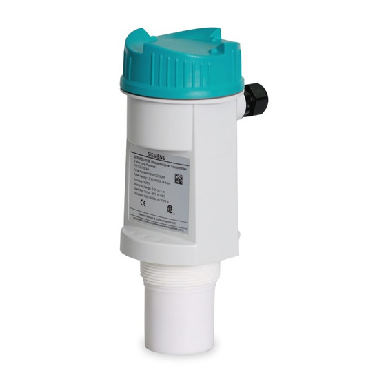
The SITRANS LU150 is an ultrasonic level monitor combining sensor and electronics in a single package. It is designed to measure liquid levels in open or closed vessels. The process part (sensor) is PVDF, allowing the SITRANS LU150 to be used in a wide variety of industries, especially food and chemical. - Page 9 Description SITRANS LU150 Operating Instructions, 03/2016, A5E34590123-AB...
-
Page 10: Installing And Mounting
① ④ Sanitary ferrule Seams ② ⑤ Pipe Fill ③ Rungs Note Mount the SITRANS LU150 so that the face of the sensor is at least 25 cm above the highest anticipated level. SITRANS LU150 Operating Instructions, 03/2016, A5E34590123-AB... -
Page 11: Threaded
Electronics ② Mounting thread ③ Sensor The SITRANS LU150 is available in three thread types: 1. 2" NPT ((Taper), ANSI/ASME B1.20.1) 2. R 2" ((BSPT), EN 10226) 3. G 2" ((BSPP), EN ISO 228-1) SITRANS LU150 Operating Instructions, 03/2016, A5E34590123-AB... - Page 12 Installing and mounting 3.3 Threaded Note Before inserting the SITRANS LU150 into its mounting hole, ensure that the threads are of the same type to avoid damaging the device. SITRANS LU150 Operating Instructions, 03/2016, A5E34590123-AB...
-
Page 13: Flange Adapter (Optional)
Installing and mounting 3.4 Flange adapter (optional) Flange adapter (optional) The SITRANS LU150 can be fitted with the optional 75 mm (3") flange adapter for mating to 3" ANSI, DIN 65PN10 and JIS 10K3B flanges. ① SITRANS LU150 ② Optional flange adapter (2" NPT - 7ML1830-1BT, 2" BSPT - 7ML1830-1BU) -
Page 14: 4" Sanitary
Mounting flange ③ Sensor Mounting the sanitary version 1. Mount the SITRANS LU150 onto the top of the tank’s sanitary ferrule. 2. Secure mating by surrounding the joint with the clamp. 3. Tighten adjusting wing nut. SITRANS LU150 Operating Instructions, 03/2016, A5E34590123-AB... - Page 15 Installing and mounting 3.5 4" Sanitary ① ④ SITRANS LU150 Ferrule ② ⑤ Clamp Tank ③ Adjusting wing nut SITRANS LU150 Operating Instructions, 03/2016, A5E34590123-AB...
- Page 16 Installing and mounting 3.5 4" Sanitary 4" Sanitary ferrule Note The inside of sanitary ferrule must be smooth, and free of burrs, seams or ridges. SITRANS LU150 Operating Instructions, 03/2016, A5E34590123-AB...
-
Page 17: Lu150 With Fms200 Mounting Bracket
Installing and mounting 3.6 LU150 with FMS200 mounting bracket LU150 with FMS200 mounting bracket ① LU150 ② FMS200 mounting bracket (7ML1830-1BK) with 7ML1830-1DT (Locknut, 2" NPT) or 7ML1830-1DQ (Locknut, 2" BSPT). SITRANS LU150 Operating Instructions, 03/2016, A5E34590123-AB... -
Page 18: Connecting
1. Loosen lid and remove it. 2. Install cable gland or conduit. 3. Insert wires through gland or conduit and up through cable guide. 4. Connect wiring. 5. Replace lid and tighten it. * Lid removed for clarity SITRANS LU150 Operating Instructions, 03/2016, A5E34590123-AB... -
Page 19: System Diagram
• Ensure the cable gland is screwed in to the enclosure tightly and the cable is within the specified clamping range (6.5 to 12 mm). • User supplied cable glands must meet IP68/NEMA 6 ratings and be installed according to the manufacturer's instructions. System diagram ① SITRANS LU150 ② Loop instrumentation SITRANS LU150 Operating Instructions, 03/2016, A5E34590123-AB... -
Page 20: Wiring Connection
Connecting 4.3 Wiring connection Wiring connection ① ④ SITRANS LU150 V supply ② Loop instrumentation ③ R max Note Power supply is reverse polarity protected. SITRANS LU150 Operating Instructions, 03/2016, A5E34590123-AB... - Page 21 Connecting 4.3 Wiring connection SITRANS LU150 Operating Instructions, 03/2016, A5E34590123-AB...
-
Page 22: Commissioning
Commissioning Start up 1. With the SITRANS LU150 correctly installed (or aimed at a wall 0.25 to 5 m away), apply power. The device starts up, displaying the following: ① ⑤ '4' key Units ② ⑥ '20' key LOE/fault ③... -
Page 23: Calibration
3. Press the key a second time to set the new distance reference. 4. After viewing or calibrating, the unit operation automatically reverts to the Run mode (6 sec). The calibration value is referenced from the face of SITRANS LU150 sensor, in the units displayed. -
Page 24: Ma Calibration
4 mA calibration retry 20 mA calibration Press "20" Press "20" again 20 mA calibration calibration invalid if new 20 mA calibration retry Note Calibration bypasses the measurement response rate. SITRANS LU150 Operating Instructions, 03/2016, A5E34590123-AB... -
Page 25: Operation Status
5.6 Operation status Operation status The graphic portion of the display gives the user a visual indication of the SITRANS LU150 operating status. During commissioning, viewing the graphic can assist the user in properly locating and installing the unit to achieve optimum performance. -
Page 26: Operating
Operating Adjustments There are several operating adjustments that can be made to the SITRANS LU150. To access the operating adjustments, simultaneously press the "4" and "20" keys until the desired adjustment is obtained. A viewing sequence of the stored value is automatically initiated. -
Page 27: Calibration, Scrolling Method
For faster scrolling, hold the key, and release it when the appropriate value is shown. 4 mA calibration 4 mA calibration initiated view stored 4 mA calibration value (i.e. 4.50 m) press ”20” to increase to new calibration value (i.e. 4.60 m) new calibration value SITRANS LU150 Operating Instructions, 03/2016, A5E34590123-AB... -
Page 28: 20 Ma Calibration
It is measured outward from the sensor face. The minimum recommended blanking value is 0.25 m (0.82 ft) but can be increased in order to extend the blanking. ① SITRANS LU150 ② Blanking SITRANS LU150... -
Page 29: Adjusting The Blanking Value
The stored blanking value is shown (for example 0.25 m) Press “20” to increase blanking value (i.e. 0.36 m) Press “4” to decrease the blanking value (i.e. 0.35 m) The new blanking value is shown. seconds SITRANS LU150 Operating Instructions, 03/2016, A5E34590123-AB... -
Page 30: Speed Of Response
The speed of response adjustment allows the user to collectively set a number of operating parameters. measurement response: is the limit to which the SITRANS LU150 will be able to keep up with rates of change. If the unit's measurement cannot keep up with the rate of level change, set the adjustment from '1' to '2'. -
Page 31: Adjusting The Speed Of Response
(Page 29), or Fail-safe timer (Page 31)), the '?' icon appears and one of the following fail-safe defaults is immediately effected. default reading full hold empty hold hold hold hold hold p = proportional span i = inversely proportional span * = factory setting SITRANS LU150 Operating Instructions, 03/2016, A5E34590123-AB... -
Page 32: Adjusting The Fail-Safe Setting
1. Press the "20" key to increase the 'waiting' period, and press the "4" key to decrease it. 2. Once you have reached the appropriate value, stop pressing the key. The display automatically returns to the Run mode (6 secs). SITRANS LU150 Operating Instructions, 03/2016, A5E34590123-AB... -
Page 33: Units
Run mode (6 secs). Indicates that the device is now in units mode. seconds The current option is shown (i.e. m) Press “20” for option 2 (i.e. ft) Option 2 has now been selected. seconds SITRANS LU150 Operating Instructions, 03/2016, A5E34590123-AB... -
Page 34: Troubleshooting
• Level inside the blanking zone The 'Waiting' period has expired. Investigate the probable caus- es listed above. Refer to Speed of response (Page 29) or Fail-safe timer (Page 31) for duration of 'Waiting' periods. SITRANS LU150 Operating Instructions, 03/2016, A5E34590123-AB... - Page 35 Troubleshooting 7.1 Troubleshooting SITRANS LU150 Operating Instructions, 03/2016, A5E34590123-AB...
-
Page 36: Technical Data
Technical data Note Siemens makes every attempt to ensure the accuracy of these specifications but reserves the right to change them at any time. Power 12 to 30 V DC (at terminal blocks), 0.1 A surge loop current 4 to 20 mA max... -
Page 37: Outputs
Ambient temperature continuous -30 to +60 °C (-22 to +140 °F) -20 °C (-5 °F) if metal mounting Relative humidity suitable for outdoor (Type 6/NEMA 6/IP68 (2 meters for 24 hours)) Installation category Pollution degree SITRANS LU150 Operating Instructions, 03/2016, A5E34590123-AB... -
Page 38: Approvals
Technical data 8.7 Approvals Approvals Approvals CE, cCSAus SITRANS LU150 Operating Instructions, 03/2016, A5E34590123-AB... - Page 39 Technical data 8.7 Approvals SITRANS LU150 Operating Instructions, 03/2016, A5E34590123-AB...
-
Page 40: Appendix
Appendix Measurement interval ① Interval (in seconds) ② mA loop current SITRANS LU150 Operating Instructions, 03/2016, A5E34590123-AB... - Page 41 Appendix A.1 Measurement interval SITRANS LU150 Operating Instructions, 03/2016, A5E34590123-AB...
- Page 42 For more information www.siemens.com/level www.siemens.com/weighing Siemens Canada Limited 1954 Technology Drive Printed in Canada P.O. Box 4225 Subject to change without prior notice Peterborough, ON A5E34590123 Rev. AB Canada K9J 7B1 © Siemens AG 2016 www.siemens.com/processautomation...