
Related Manuals for Mitsubishi MELFA SQ Series


Summary of Contents for Mitsubishi MELFA SQ Series
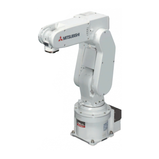
- Page 1 Mitsubishi Industrial Robot Series RV-2SQ/2SQB Standard Specifications Manual (CR1QA-700 series Controller) BFP-A8777-R...
-
Page 3: Safety Precautions
Safety Precautions Always read the following precautions and the separate "Safety Manual" before starting use of the robot to learn the required measures to be taken. CAUTION CAUTION WARNING CAUTION WARNING CAUTION CAUTION CAUTION... - Page 4 CAUTION CAUTION CAUTION CAUTION CAUTION CAUTION WARNING WARNING CAUTION WARNING CAUTION CAUTION CAUTION CAUTION WARNING...
- Page 5 CAUTION CAUTION CAUTION CAUTION コントローラ 漏電遮断器 (NV) 端子カバー 電源端子台 端子カバー アース接続ネジ 保護アース端子 (PE)
- Page 6 コントローラ 漏電遮断器 (NV) Note) Please prepare by KEY11 KEY12 KEY21 the customer in the KEY22 端子カバー DU1A-772 drive unit. Note) The figure is 電源端子台 DU1A-772 Drive unit. 端子カバー アース接続ネジ 保護アース端子 (PE)
- Page 7 Date of print Specifications No. Details of revisions 2010-02-04 BFP-A8777 ・ First print. 2010-02-12 BFP-A8777-A ・ Power capacity was corrected.(old value: 0.2kVA) 2010-03-30 BFP-A8777-B ・ CE specification of the CR1QA controller was added. ・ Specification of RV-2SQB (all the axis have brakes) was added. 2010-06-17 BFP-A8777-C ・...
- Page 8 About KC mark specifications...
- Page 9 Contents Page...
- Page 10 Contents Page...
- Page 11 Contents Page...
- Page 12 1General configuration 1 General configuration 1.1 Structural equipment 1.1.1 Standard structural equipment 1.1.2 Special specifications 1.1.3 Options 1.1.4 Maintenance parts Structural equipment...
-
Page 13: Indirect Export
1General configuration 1.2 Model type name of robot 1.2.1 How to identify the robot model RV-2SQ B -Sxx ( a ) ( b ) (c ) (a). (b). (c). 1.2.2 Combination of the robot arm and the controller Note1) Protection specification Robot arm Axial constitution Controller... -
Page 14: Contents Of The Structural Equipment
1General configuration 1.6 Contents of the structural equipment 1.6.1 Robot arm Machine cable extension <Standard specification/CE marking S16 specification> ・ 1S- □□ CBL-11 ・ 1S- □□ LCBL-11 <CE marking S15 specification> ・ 1S- □□ CBL-03 ・ 1S- □□ LCBL-03 Note1) □□ refer the length. Refer to Page 5, "Table 1-3"... -
Page 15: General Configuration
General configuration 1.6.2 Controller ・ CR1QA-700 series *2) Cable ・ 2Q-TUCBL 10m (TU Cable for robot) ・ 2Q-DISPCBL10m (DISP Cable for robot ) The base board, the power supply ・ 2Q-EMICBL 10m (EMI Cable for robot) unit, and sequencer CPU are required for installation of the ・... -
Page 16: Contents Of The Option Equipment And Special Specification
General configuration 1.7 Contents of the Option equipment and special specification Classification Item Type Specifications Description Note1) J1 axis Stopper for changing the 1S-DH-11J1 + side: +210、 +150、 +90 deg. operating range - side: -210、 -150、 -90 deg. ○ One place selection is possible each for + side / - side. - Page 17 Supplier KU-AMB530 SANWA SUPPLY INC. (USB A type-USB mini B type) USB-M53 ELECOM CO., LTD. GT09-C30USB-5P MITSUBISHI ELECTRIC SYSTEM & SERVICE CO., LTD. MR-J3USBCBL3M MITSUBISHI ELECTRIC CO., LTD. USB adapter AD-USBBFTM5M ELECOM CO., LTD. (USB B type-USB mini B type)
-
Page 18: 2Robot Arm
2Robot arm 2 Robot arm 2.1 Standard specifications Item Unit Specifications Note1) Type RV-2SQ/2SQB Degree of freedom 6 Installation posture On floor, hanging Note2) (against wall Structure Vertical, multiple-joint type Drive system AC servo motor (RV-2S : J2, J3, J5 axes have the brake) (RV-2S B: All axes have the brake) Position detection method... -
Page 19: Definition Of Specifications
2 Robot arm 2.2 Definition of specifications 2.2.1 Pose repeatability Definition of specifications... - Page 20 2 Robot arm 2.2.2 Rated load (mass capacity) Unit : mm 単位 : mm 1.0kg J5 axis rotation center J5軸回転中心 2.0kg J6 axis rotation center J6軸回転中心...
-
Page 21: Robot Arm
2 Robot arm 2.2.3 Protection specifications (1) Types of protection specifications Protection Type specifications Classification Applicable field Remarks (IEC Standards value) General environ - RV-2SQ/2SQB Robot arm:IP30 General assembly ment specifications (all axes) Slightly dusty environment... - Page 22 2 Robot arm 2.3 Names of each part of the robot フォアアーム + リスト J4軸 ツイスト - J5軸 + + J3軸 - - - + - エルボ J6軸 ロール メカニカルインタフェース (ハンド取付フランジ面) + アッパーアーム J2軸 - ショルダ ウエスト - + J1軸 ベース...
-
Page 23: Outside Dimensions ・ Operating Range Diagram
2 Robot arm 2.4 Outside dimensions ・ Operating range diagram (1) RV-2SQ (standard specification/CE marking S16 specification) screw depth 6 screw screw screw depth 6 depth 6 depth 6 View C screw screw depth 6 (Grounding) Minimum depth 8 depth 8 installation hole (Installation) Rz 25... - Page 24 2 Robot arm (2) RV-2SQB-S15 (CE marking S15 specification) screw depth 6 screw 2-M3 screw screw depth 6 depth 6 depth 6 View C screw screw depth 6 (Grounding) Minimum depth 8 screw depth 8 View A installation hole (Installation) Detail of mechanical interface View B Detail of installation dimension...
- Page 25 2 Robot arm (3) Operating range (Common to the standard/CE Marking) P-point path Flange downward limit line P-point path Control point (R-point) Flange upward limit line Flange downward Note) The posture of side view The case where the angle of each axis is the following is shown singular point limit J1=0 degree, J2=0 degree, J3=90 degree, J4=0 degree, J5=0 degree., J6=0 degree.
- Page 26 2 Robot arm 2.5 Tooling 2.5.1 Wiring and piping for hand (1) RV-2SQ (Standard specification/CE marking S16 specification) (1)Hand input signal connectors Hand input signal cables Solenoid valve set (optional) Opposite side of figure AWG24 (0.2mm ) x 2 core: Four installation section Secondary piping hoses (φ4*4)
- Page 27 2 Robot arm (2) RV-2SQB (CE marking S15 specification) (1)Hand input signal connectors Hand input signal cables (CON1H) Solenoid valve set(optional) Note) Opposite side of figure AWG24 (0.2mm ) x 2 core: Four installation section Secondary piping (3)1 to 4 : Secondary piping hoses (φ4*4) couplings (φ4) Secondary piping...
- Page 28 2 Robot arm 2.5.2 Internal air piping 2.5.3 Internal wiring for the pneumatic hand output cable 2.5.4 Internal wiring for the hand check input cable Tooling...
- Page 29 2 Robot arm 2.5.5 Wiring and piping system diagram for hand General-purpose General-purpose input No. input No. <ハンドチェック 1> 汎用入力900 <ハンドチェック 2> 汎用入力901 <ハンドチェック 3> 汎用入力902 <ハンドチェック 4> 汎用入力903 ロボット コントローラ Reserve 予約 <+24V> <0V(COM)> Reserve 予約 1 +24V 2 1 2 +24V 1 +24V 2...
- Page 30 2 Robot arm General-purpose General-purpose input No. input No. <ハンドチェック 1> 汎用入力900 <ハンドチェック 2> 汎用入力901 <ハンドチェック 3> 汎用入力902 <ハンドチェック 4> 汎用入力903 ロボット コントローラ Reserve 予約 <+24V> <24GND> Reserve 予約 1 24GND 2 1 2 24GND 1 24GND 2 1 2 24GND Solenoid valve 電磁弁の φ4 quick coupling bridge(1 to 4) φ4 quick coupling bridge(1 to 4) φ4クイック継手渡し(1~4)...
- Page 31 2 Robot arm 2.5.6 Electrical specifications of hand input/output Item Specifications Internal circuit Type DC input No. of input points Insulation method Photo-coupler insulation Rated input voltage 12VDC/24VDC Rated input current Approx. 3mA/approx. 7mA HCn * Working voltage range DC10.2 to 26.4V(ripple rate within 5%) 3.3K ON voltage/ON current 8VDC or more/2mA or more...
- Page 32 2 Robot arm 2.5.7 Air supply circuit example for the hand Pressure switch To the solenoid valve primary air supply port (0.5MPa) Pneumatic source Filter Regurater 0.7MPa or less...
- Page 33 2 Robot arm 2.6 Options Options...
-
Page 34: Machine Cable Extension
2 Robot arm (1) Machine cable extension Qty. Mass(kg) Note1) Part name Remarks Type Note2) Fixed Flexed Standard specification/CE marking S16 specification Fixed Set of signal and power cables 1S- □□ CBL-11 1 set 7.6(10m) 10m, or 15m each 10.9(15m) (standard specification/CE Motor signal cable 1S- □□... - Page 35 2 Robot arm Item Specifications Minimum flexed radius 100R or more Cableveyor, etc., occupation rate 50% or less Maximum movement speed 2000mm/s or less Guidance of life count 7.5 million times Environmental proof Oil-proof specification sheath (for silicon grease, cable sliding lubricant type) Cable configuration Motor signal cable Standard specification/CE marking S16 specification: φ6 x 6...
- Page 36 2 Robot arm Motor power モータパワー Drive unit (CN1) DU1A-772/DU1A-771-S16 Robot arm ロボット本体 (Opposite side of figure) (ベース部背面) Connection ring 接続リング部 (fixing) (固定) Motor signal モータ信号 (CN2) Motor signal cable Connection latch ラッチ Connection latch モータ信号ケーブル ラッチ (固定用 左右) (For fixing. Right and left ) Connection ring 接続リング部...
- Page 37 2 Robot arm Motor power モータパワー Drive unit (CN1) Robot arm DU1A-771-S15 Connection latch ラッチ ロボット本体 (Opposite side of figure) (ベース部背面) Motor signal モータ信号 (CN2) Nylon clamp ナイロンクランプ NK-14N ラッチ Motor signal cable モータ信号ケーブル Connection latch ラッチ Connection latch ラッチ Connection latch Motor power cable モータパワーケーブル...
-
Page 38: Changing The Operating Range
2 Robot arm (2) Changing the operating range Part name Type Qty. Mass(kg) Remarks Stopper for changing the operat - 1S-DH-11J1 2 pcs. Stopper block Moving side : One Set ing range Fixing side : Two blocks Installation bolt (M5 x 20) : Six bolts 1S-DH-11J2 2 pcs. -
Page 39: Solenoid Valve Set
2 Robot arm (3) Solenoid valve set ■ Outline Q'ty Part name Type Remark sets Solenoid valve set (1 set) 1E-VD01/1E-VD01E 1 pc. - M3 x 25 two screws (installation screws). Solenoid valve set (2 sets) 1E-VD02/1E-VD02E - 1 pc. Item Specifications Number of positions... - Page 40 2 Robot arm (1)(4) 35.6 SOL2A SOL1A (12) 2-φ 3.3 SOL1B SOL2B 28.4 (45) or less (45) 以下 36.4 (20) 以下 (20) or less (10)(11) <Sink type> Connector name Part Black General purposes Part name 1 sets 2 sets Specifications ...
- Page 41 2 Robot arm (4) Hand input cable Note1) Part name Type Qty. Remarks Mass(kg) Hand input cable 1S-HC30C-11 1 cable Item Specifications Remarks Size x cable core One-sided connector, one-sided cable bridging AWG#24 (0.2mm )×12 Total length 370mm (Including the curl section) 1-1827864-6 200±10 CON1H...
-
Page 42: Hand Output Cable
2 Robot arm (5) Hand output cable Note1) Mass(kg) Part name Type Qty. Remarks Hand output cable 1E-GR35S 1 cable Item Specifications Remarks Size x Cable core AWG#22(0.3mm )×8 cores One side connector and one side cable connection Total length 350mm (1)(2) *... -
Page 43: Hand Curl Tube
2 Robot arm (6) Hand curl tube Note1) Part name Type Qty. Remarks Mass(kg) Hans curl tube (One set: 2 pcs.) 1E-ST0402C 1 pc. Φ4 tube, 2pcs. Hans curl tube (Two set: 4 pcs.) 1E-ST0404C 1 pc. Φ4 tube, 4pcs. Item Specifications Material... -
Page 44: About Overhaul
Periodic inspection haul If overhaul is performed Servo-on time 2.8 Maintenance parts Note1) Part name Usage place Qty. Supplier Type Grease SK-1A Reduction gears of each axis As needed Mitsubishi Electric Lithium battery In the battery cover 4 pcs. About Overhaul... - Page 45 Controller 3 Controller 3.1 Standard specifications 3.1.1 Standard specifications Item Unit Specification Remarks DU1A-771 is the CE marking specifica - Type CR2QA-772/CR1QA-772 tion. Number of control axis Simultaneously 6(Maximum) 6 4 bit R I S C / D S P Memory Programmed positions and No.
- Page 46 Controller Item Specification Remarks Unit DU1A-771 is the CE marking specifi - Type DU1A-771/DU1A-772 cation. External input and output point Input 0 point/Output 0 point Multi-CPU share device input Input 8192/Output 8192 (Max.) Dedicated input/ Assign to the multi-CPU share device. and out - output Special stop input...
-
Page 47: Protection Specifications And Operating Supply
Controller Item Unit Specification Remarks Type Q172DRCPU Interface Addition axis synchronization port 1 Power source Power capacity (DC5V) 1 . 2 5 Outline dimensions 2 7 . 4 (W) x 9 8 (D) x 1 1 9 . 3 (H) Mass 0... -
Page 48: Standard Specification
Controller 3.2 Names of each part 3.2.1 Names of each part of the drive unit <DU1A-772> Standard specification... - Page 49 Controller <DU1A-771-S15/S16> CE marking specification ⑬ ⑧ ② ⑥ ④ ⑤ ⑩ ⑫ ⑭ Power cable clamp ⑪ ⑦ ⑨ ③ * 1) POWER switch........This turns the control power ON/OFF. (With earth leakage breaker function) START button........This executes the program and operates the robot. The program is run continuously. STOP button ........This stops the robot immediately.
- Page 50 Controller (1) Padlock specification Dimension (mm) 4mm or less...
- Page 51 Controller DU1A-772 Standard specification ⑦ ① ⑧ Connect with the robot CPU unit. ⑨ ② ⑩ ⑥ ⑪ ③ ④ ⑤...
- Page 52 Controller DU1A-771-S15/S16 ⑦ ① ① ⑧ ⑨ ⑩ ② ② ⑥ ⑪ A) Connect with robot CPU unit ⑤ ③ ④...
- Page 53 Controller 3.2.2 Names of each part of the robot CPU ⑨ ① ⑩ ③ Q172DRCPU ⑫ ② ④ ⑬ STOP ⑤ CAUTION ⑥ ⑭ ⑦ FRONT ACFAIL ⑪ Front Back ⑧ Side 背面 側面 正面...
- Page 54 3 Controller 3.3 Outside dimensions/Installation dimensions 3.3.1 Outside dimensions (1) Drive unit outside dimension <DU1A-772> Standard specification Outside dimensions/Installation dimensions...
- Page 55 3 Controller <DU1A-771-S15> CE marking specification Outside dimensions/Installation dimensions...
- Page 56 3 Controller <DU1A-771-S16> CE marking specification Outside dimensions/Installation dimensions...
- Page 57 3 Controller (2) Outside dimensions of robot CPU unit Outside dimensions/Installation dimensions...
- Page 58 3 Controller (3) Battery unit outside dimension 2-Φ5.5 hole Outside dimensions/Installation dimensions...
- Page 59 3 Controller 3.3.2 Installation dimensions (1) Installation dimensions of drive unit <DU1A-772> 50mm 20mm Standard specification Intake vent 吸気口 170 mm or more 170mm以上 <DU1A-771-S15/S16> 50mm 20mm CE marking specification Intake vent 吸気口 170mm or more 170mm以上 Outside dimensions/Installation dimensions...
- Page 60 3 Controller (2) Robot CPU Unit installation dimensions <Q172DRCPU> The position of the ceiling of the board, and the wiring duct section 盤の天井、配線ダクト部分の位置 Base unit ベースユニット Robot CPU Unit ロボットCPUユニット Robot CPU Unit Within 40mm ロボットCPUユニット 40mm以上 Q 172D RCPU QX40 QX40 Q172DEX...
- Page 61 3 Controller 3.3.3 Cable lead-in and dimension <DU1A-700 series> Input power supply lead-in (15x22) Outside dimensions/Installation dimensions...
-
Page 62: External Input/Output
3 Controller 3.4 External input/output 3.4.1 Types External input/output... -
Page 63: Dedicated Input/Output
3 Controller 3.5 Dedicated input/output Input Output Parameter Note1) name Name Function Level Name Function Teaching mode out - TEACHMD None Outputs that the teaching mode is put signal entered. Automatic mode out - ATTOPMD None Outputs that the automatic mode is put signal entered. - Page 64 3 Controller Input Output Parameter Note1) name Name Function Level Name Function PRGSEL Program selection Designates the setting value for input signal the program No. with numeric value E None input signals. OVRDSEL Override selection Designates the setting value for input signal the override with the numeric value E...
- Page 65 3 Controller 3.6 Emergency stop input and output etc. Item Name Function Input Emergency stop Applies the emergency stop. Dual emergency line Input Special stop input Applies the stop. (Refer to Page 57, "3.6.2 Special stop input(SKIP)") Input Door switch Servo-off.
- Page 66 3 Controller CAUTION <DU1A-700 series> EMGINコネクタ 300mm以内 Ferrite core フェライトコア(付属品) (attachments) 2回通し Pass twice Emergency stop input and output etc.
- Page 67 3 Controller Internal circuit structure (Customer) (Controller) (Customer) EMG. stop EMG. stop EMGOUT1 EMGIN1 +24V Short Robot error output External emergency input Mode output Relay (prepare by customer) Add. axis contacts Short control output (AXMC1) 24GND +24V Door switch input Relay (prepare by customer) +24V...
- Page 68 3 Controller CAUTION CAUTION 3.6.2 Special stop input(SKIP) Item Specifications Internal circuit Type DC input No. of input point Insulation method Phto-coupler insulation Rated inpit voltage DC24V Rated input current approx. 11mA +24V(COM) Working voltage range DC 21.6 ~ 26.4V (Ripple rate within 5...
- Page 69 3 Controller 300mm or less Ferrite core フェライトコア(付属品) (attachments) 2回通し SKIP Pass twice 専用停止入力コネクタ(SKIP) 電線差込口(AWG#24-18) マイナスドライバ差込口 Emergency stop input and output etc.
- Page 70 3 Controller 3.6.3 Door switch function Safeguard STOP!! MODE TEACH MANUAL AUTOMATIC AUTO AUTO (Op.) (Ext.) Robot arm Open (Example) Turns OFF the servo Safeguard MODE TEACH MANUAL AUTO AUTOMATIC AUTO (Op.) (Ext.) Teaching pendant Robot arm Open (Example) The servo can be turned ON/Off by turning the enable switch ON/OFF.
- Page 71 3 Controller (3) Automatic Operation/Jog Operation/Brake Release and Necessary Switch Settings Note1) Note2) Related switch settings Mode of Enabling Door switch Operation Description controller enable/ enable switch device input input terminal disable terminal If the enabling device input is set to Jog operation Manual Enable...
- Page 72 3 Controller 3.7 Additional Axis Function 3.7.1 Wiring of the Additional Axis Interface Name Connector name Details Note1) Connector for additional axes The connector for connecting robot CPU with general-purpose servo amplifier. Magnet contactor control connector EMGOUT This contact output is used to turn ON/OFF the motor power by for additional axes connecting to general-purpose servo amplifiers.
- Page 73 3 Controller <DU1A-700 series> EMGOUT Robot CPU ロボットCPU Servo amplifier Servo amplifier サーボアンプ サーボアンプ (Q172DRCPU) (Q172DRCPU) Q172DRCPU STOP SSCNET Ⅲ cable SSCNET Ⅲ cable CAUTION SSCNETⅢケーブル SSCNETⅢケーブル Ferrite core CN1A connector フェライトコア CN1A connector CN1Aコネクタへ CN1Aコネクタへ (Only for the CE (CE仕様のみ)...
- Page 74 3 Controller 3.8 Magnet contactor control connector output (AXMC) for addition axes 1) Get the power supply for the controller from the secondary erminal of short circuit breaker (NV) built in the addition axis amplifier box. Amplifier 2) Get the power supply for the MC synchronization from the secondary terminal of short circuit breaker (NV) built in the controller.
- Page 75 3 Controller <DU1A-700 series> <Reference> The connection method of the electric wire is EMGOUT EMGOUTコネクタ the same as connection of the emergency stop. Please refer to Page 54, "3.6.1 Connection of the external emergency stop" EMGOUTコネクタ配列図 内部回路構成 Electric wire plug area 電線差込み口...
- Page 76 3 Controller 3.9 Key switch interface (Only for the DU1A-772 drive unit) MODE MANUAL AUTOMATIC (1) Specification of the key switch interface Note1) Name and Function Change mode Name Function MANUAL AUTOMATIC KEY11 KEY11 1st line KEY input Open Close KEY12 KEY12 Power supply +24V of KEY11...
- Page 77 3 Controller (2) Connection of the key switch interface Terminal opening-and-closing lever Terminal Push the lever by the minus driver Connect the electric wire. (recommendation size: 2.0-3.0mm) etc., Peel sheathing about 10mm. and insert the electric wire in the terminal. KEY11 KEY12 KEY21...
- Page 78 3 Controller 3.10 Options...
-
Page 79: Teaching Pendant (T/B)
3 Controller (1) Teaching pendant (T/B) Note1) Part name Type Qty. Remarks Mass(kg) Teaching pendant R32TB Cable length is 7m. Hand strap is attached. Either one pc. R32TB-15 Cable length is 15m. Hand strap is attached. Items Specifications Remarks Outline dimensions 195(W) x 292(H) x 106(D) (refer to outline drawing) Body color Dark gray... - Page 80 3 Controller 195.2 105.5 Enable/Disable switch Emergency stop Operetion key Body Enable switch Cable (with connector) <Back> <Front> <side> <Bottom> Teaching pendant (T/B)
- Page 81 3 Controller ② ④ ① ③ ⑤ ⑤ ⑥ ⑥ ⑧ ⑦ ⑨ ⑩ ⑪ ⑰ ⑫ ⑱ ⑬ ⑭ ⑲ ⑮ ⑯ ⑳ Teaching pendant (T/B)
-
Page 82: Pneumatic Hand Interface
3 Controller (2) Pneumatic hand interface Note1) Part name Type Qty. Remarks Mass(kg) Pneumatic hand interface 2A-RZ365(Sink type) Either Output 8 points expansion. one pc. 2A-RZ375(Source type) Item Specification Internal circuit Type Transistor output No. of output points Insulation method Photo coupler insulation (Internal power supply)... - Page 83 3 Controller Pneumatic hand interface エアハンドインタフェース (2A-RZ365/RZ375) (2A-RZ365/2A-RZ375) Hand interface relay card ハンドインタフェース中継カード (2D-TZ315) View A 矢視A CNHND CNHND M4ネジ(2箇所) CNHNDOUT CNHNDOUT Pneumatic hand interface エアハンドインタフェース Pneumatic hand interface...
- Page 84 3 Controller (3) Key switch extension cable (Only for the DU1A-772 drive unit) Part name Type Qty. Remarks Key switch extension cable 2D-KEY-CBL05M/ Either one pc. The key switch, with the connecting cable 2D-KEY-CBL10M/ Key switch maker: IDEC 2D-KEY-CBL15M Type: HAIK-2C2A-2-TK2469 Indication seal BU764D213H01...
- Page 85 3 Controller Grounding cable Notes) Connect the grounding cable to the unpainted portion on the operation panel which prepared by customer. Key switch Operation panel which prepared by customer キースイッチインタフェース Terminal opening-and-closing lever Push the lever by the minus driver (recommendation size: 2.0-3.0mm) etc., and insert the electric wire in the terminal.
- Page 86 3 Controller (4) TB extension cable Part name Type Qty. Remarks TB extension cable 2D-EXTB-CBL05M/ Either one pc. 2D-EXTB-CBL10M/ 2D-EXTB-CBL15M Indication seal BU764D213H02 One sheet The indication of TB TB extension cable installation manual BFP-A8770 One c opy TB extension cable Operation panel etc which prepared by customer TB extension cable...
- Page 87 3 Controller Indication seal (accessories) Square hole Indication seal Installation hole Turn the triangle mark to upward. TB extension cable socket Operation panel surface Notes) The board thickness which can Case be installed is 0.5mm to 2.3mm. 4-M3 x 8 screw Installation of TB extension cable Fix the scalpel side connector to the operation panel etc of customer preparation.
- Page 88 3 Controller (5) RT ToolBox2/RT ToolBox2 mini RT ToolBox2 RT ToolBox2 mini Note1) Part name Type Medium Remarks Mass(kg) RT ToolBox2 3D-11C-WINE CD-ROM RT ToolBox2 mini 3D-12C-WINE CD-ROM RT ToolBox2/RT ToolBox2 mini...
- Page 89 3 Controller Note1) Function Details Functional existence Compatible model ○ ○ Personal computer running Microsoft Windows2000/XP/Vista. Program editing Editing functions ・ MELFA BASIC V language compatible functions ・ Multiple editing screen simultaneously display ・ Command input, comment writing ・ Position data editing ・...
- Page 90 3 Controller (6) Instruction Manual(bound edition) Note1) Specifications Name Type Mass(kg) Instruction Manual 5S-QJ00-PE01 The instructions manual set of "RV-2SD". Safety Manual BFP-A8006 Items relating to safety in handling the robot Standard Specifications BFP-A8777 Specification of the robot arm and controller Installation method of the robot arm, jog operation, Robot Arm Setup &...
- Page 91 3 Controller 3.11 Maintenance parts Note1) Name Qty. Usage place Supplier Type CR1QA-700 series controller Lithium battery Q6BAT Robot CPU unit Mitsubishi Electric Sys - tem Service;Co.,Ltd Filter Front of the controller Maintenance parts...
-
Page 92: List Of Commands
4Software 4 Software 4.1 List of commands Type Class Function Input format (example) Joint interpolation Moves to the designated position with joint interpolation. Mov P1 Linear interpolation Moves to the designated position with linear interpolation. Mvs P1 Circular interpolation Moves along a designated arc (start point → passing point → start point Mvc P1,P2,P1 (end point)) with 3-dimensional circular interpolation (360 degrees). - Page 93 4Software Type Class Function Input format (example) Branching Branches unconditionally to the designated place. GoTo 120 Branches according to the designated conditions. If M1=1 Then GoTo *L100 Else GoTo 20 End If Repeats until the designated end conditions are satisfied. For M1=1 TO 10 Next M1 Repeats while the designated conditions are satisfied.
- Page 94 4Software Type Class Function Input format (example) Definition Defines the integer type or real number type variable. Def Inte KAISUU Defines the character string variable. Def Char MESSAGE efines the layout variable. (Up to 3-dimensional possible) Dim PDATA(2,3) Defines the joint variable. Def Jnt TAIHI Defines the position variable.
- Page 95 4Software 4.2 List of parameters Parameter Details Standard tool coordinates. MEXTL Set the default value for the tool data. Unit: mm or deg. Standard base coordinates MEXBS Set the relation of the world coordinate system and robot coordinate system. Unit: mm or deg. XYZ operation range MEPAR Designate the overrun limit value for the world coordinate system.
-
Page 96: List Of Parameters
4Software Parameter Details Hand type HANDTYPE Set the hand type of the single/double solenoid, and the signal No. (Single/double = S/D) Set the signal No. after the hand type. Example) D900 Stop input B contact desig - Change the dedicated input (stop) between the A contact and B contact. nation User-designated origin USERORG... - Page 97 5Instruction Manual 5 Instruction Manual 5.1 The details of each instruction manuals Troubleshooting Additional axis function Tracking Func - tion Manual The details of each instruction manuals...
- Page 98 5Instruction Manual Extended Func - tion Instruc - tion Manual The details of each instruction manuals...
-
Page 99: Self-Diagnosis Stop Functions
6Safety 6 Safety 6.1 Safety 6.1.1 Self-diagnosis stop functions Function Details Remarks Overload protection func - Activates when the total servo current time exceeds The drive circuit is shut off. The robot stops, and tion the specified value. an alarm displays. Overcurrent diagnosis Activates when an overcurrent flows to the motor The drive circuit is shut off. - Page 100 6Safety 6.1.2 External input/output signals that can be used for safety protection measures Connection Signal Parameter Functions Usage method point External emer - Terminal This servo power is shut off, and the robot Externally installed emergency stop switch. gency stop (EMG IN) stops immediately.
- Page 101 6Safety 6.1.4 Safety measures for automatic operation 6.1.5 Safety measures for teaching 6.1.6 Safety measures for maintenance and inspections, etc. Safety...
- Page 102 6Safety 6.1.7 Examples of safety measures <Wiring example 1>: Connect the emergency stop switch of peripheral equipment to the robot controller. The power supply for emergency stop input uses the power supply in the robot controller. <Operation of the emergency stop> If the emergency stop switch of peripheral equipment is pushed, the robot will also be in the emergency stop state.
- Page 103 6Safety <Wiring example 2>: Connect the emergency stop switch of peripheral equipment to the robot controller. The power supply for emergency stop input uses the power supply of peripheral equipment. <Operation of the emergency stop> If the emergency stop switch of peripheral equipment is pushed, the robot will also be in the emergency stop state.
- Page 104 6Safety <Wiring example 3>: Connect the emergency stop switch, door switch, and enabling device of peripheral equipment to the robot controller. The power supply for emergency stop input uses the power supply of peripheral equipment. Monitor the emergency stop state by the peripheral equipment side. <Operation of the emergency stop>...
- Page 105 6Safety <Wiring example 4>: Connect the emergency stop switch of peripheral equipment, and the door switch to two robot controllers, and it interlocks. Connect the enabling device to the robot controller.The power supply for emergency stop input uses the power supply of peripheral equipment. Monitor the emergency stop state by the peripheral equipment side.
- Page 106 6Safety (1) External emergency stop connection [supplementary explanation] Emergency stop switch Robot controller (2-contact type) EMGIN1/2 Peripheral Power supply in the equipment robot controller OP Emergency 24V 1A/1B Power stop button Not connected supply 24V 2A/2B 3A/3B 4A/4B TB Emergency 5A/5B stop button 6A/6B...
- Page 107 6Safety 6.2 Working environment CAUTION 6.3 Precautions for handling Working environment...
- Page 108 6Safety Precautions for handling...
- Page 109 7Appendix 7 Appendix Appendix 1 : Specifications discussion material Company name Name Address Telephone Note1) Specification Type Standard specification □ RV-2SQ □ RV-2SQB Note2) CE Marking specification □ Not provided □ "-S15"specification(CR1QA-700-S15) □ "-S16"specification(CR1QA-700-S16) Item Standard specifications Special shipping specifications Robot arm Machine cable □...
- Page 138 HEAD OFFICE: TOKYO BUILDING, 2-7-3, MARUNOUCHI, CHIYODA-KU, TOKYO 100-8310, JAPAN NAGOYA WORKS: 5-1-14, YADA-MINAMI, HIGASHI-KU, NAGOYA 461-8670, JAPAN Jul., 2012 MEE Printed in Japan on recycled paper. Specifications are subject to change without notice.