Table of Contents
Advertisement
Quick Links
PW
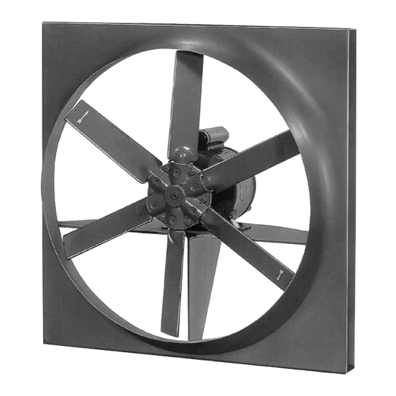
Wall Mounted Prop Fans
OPERATION & MAINTENANCE
Revised: AUGUST 2016
IMPORTANT!
READ BEFORE PROCEEDING!
The information contained herein is, to the best of our knowledge, accurate and applicable for proper operation and installation of
the specified equipment at the time this document entered service. Before proceeding, it is recommended that you check for a more
current version of this Installation Operation Manual (IOM) on our website at www.johnsoncontrols.com.
Read carefully before attempting to assemble, install, operate or maintain the product described. Protect yourself and others by
observing all safety information. Failure to comply with instructions could result in personal injury and/or property damage! Retain
instructions for future reference.
Advertisement
Table of Contents

Related Manuals for York PW Series


Summary of Contents for York PW Series
- Page 1 Wall Mounted Prop Fans OPERATION & MAINTENANCE Revised: AUGUST 2016 IMPORTANT! READ BEFORE PROCEEDING! The information contained herein is, to the best of our knowledge, accurate and applicable for proper operation and installation of the specified equipment at the time this document entered service. Before proceeding, it is recommended that you check for a more current version of this Installation Operation Manual (IOM) on our website at www.johnsoncontrols.com.
-
Page 2: Surface Protection
INTRODUCTION YORK® by Johnson Controls fans consist of a fan housing, LONG TERM STORAGE (OVER 1 MONTH) impeller, shaft, bearings, and motor mounting plate (where Long-term storage is defined as storage for period exceeding required). All impellers are statically and dynamically balanced. -
Page 3: Installation
. . . be sure it is not running and cannot be operated before HEAT FAN PACKAGE doing any inspection or maintenance. All YORK® by Johnson Controls heat fan packages are designed DO NOT operate fan with guards removed. based on a maximum temperature rise of 15°F/min. - Page 4 Important Note: Motors are warranted by the motor variation in voltage, a 5% variation in frequency or a combination manufacturer. YORK® by Johnson Controls will assist in voltage-frequency variation of 10%. For motors rated 208-220 locating a local vendor approved repair shop, if required.
-
Page 5: Motor Lubrication
START-UP MOTOR LUBRICATION START-UP Regrease or lubricate motor bearings according to manufacturer’s Before Start-Up: recommendations. DO NOT OVER LUBRICATE. Motor manufacturer’s lubrication recommendations are printed on tags Fastenings - It is recommended that all foundation bolts, attached to motor. Should these tags be missing the following impeller hub set screws and bearing set screws be checked for will apply: tightness before start up. -
Page 6: Maintenance
START-UP (CONTINUED) AND MAINTENANCE Dampers and Variable Inlet Vanes (VIVs) - They should Fans should be inspected for wear and dirt periodically. Any operate freely with blades closed tightly. All dampers and VIVs dirt accumulated in housing should be removed. The impeller should be partially closed during starting periods to reduce power may have to be cleaned. - Page 7 MAINTENANCE (CONTINUED) Adjustable Motor Base When grease is added, use caution to prevent any dirt from Belt drives can be aligned and adjusted by loosening clamping entering the bearing. The pipe plug or grease relief fitting should bolts and sliding motor axially and retightening. Belt tension can be open when greasing to allow excess grease to flow out.
- Page 8 MAINTENANCE (CONTINUED) Base your particular interval on condition of grease after a 2. Move motor on base so belts can be placed in grooves of specific service period.The chart below is intended as a guideline both sheaves without forcing. Do not roll belts or use tool for your consideration.
- Page 9 When ordering replacement parts it is necessary to provide be locked “off” for personal safety. The position of mating parts YORK® by Johnson Controls with the serial number of the unit such as bearing, drive, etc., should be marked in their relative and/or the original shop order number on which the fan was position for simplifying assembly.
- Page 10 GUIDELINES GUIDELINES FOR INTERPRETING THE CLASSIFICATIONS ON THE SEVERITY CHART Smooth: Alignment, balance and the integrity of the support structure must be near perfect and the vibration from sources other than the fan equipment must be low. Good: Requires reasonable care on installation, proper foundation, good balance on the rotating components and good alignment of the running gear.
-
Page 11: Troubleshooting Checklist
TROUBLESHOOTING CHECKLIST Symptom Possible Cause(s) Corrective Action Total resistance of system higher than anticipated. System problems. Speed too low. Adjust drive. Capacity or Dampers or variable inlet varies improperly adjusted. Adjust. Pressure Poor fan inlet or outlet conditions. Elbows at or too close to fan. Below Rating Air leaks in system. - Page 12 Exchange, repair or replacement will be provided on a no charge basis if the motor is defective within the warranty period. The YORK® by Johnson Controls representative in your area will provide a name and address of an authorized service station if requested.