
Related Manuals for Juniper NSM4000


Summary of Contents for Juniper NSM4000
- Page 1 NSM4000 Appliance Hardware Guide Modified: 2016-11-23 Copyright © 2016, Juniper Networks, Inc.
- Page 2 END USER LICENSE AGREEMENT The Juniper Networks product that is the subject of this technical documentation consists of (or is intended for use with) Juniper Networks software. Use of such software is subject to the terms and conditions of the End User License Agreement (“EULA”) posted at http://www.juniper.net/support/eula.html.
-
Page 3: Table Of Contents
Front Panel of an NSM4000 Appliance ........ - Page 4 Unpacking the NSM4000 Appliance ........29...
- Page 5 Managing Users ..........81 Creating New NSM4000 Appliance Users ......81 Deleting a User .
- Page 6 Maintaining the Hardware ......... 109 Maintaining an NSM4000 Appliance ........109 Chapter 12 Replacing Hardware Components .
- Page 7 NSM4000 Appliances ........
- Page 8 Compliance Information ......... . . 173 Agency Approvals for the NSM4000 Appliance ......173 Compliance Statements for EMC Requirements for the NSM4000 Appliance .
-
Page 9: About The Documentation
® To obtain the most current version of all Juniper Networks technical documentation, see the product documentation page on the Juniper Networks website at http://www.juniper.net/techpubs/ If the information in the latest release notes differs from the information in the documentation, follow the product Release Notes. - Page 10 RFC 1997, BGP Communities Attribute Italic text like this Represents variables (options for which Configure the machine’s domain name: you substitute a value) in commands or [edit] configuration statements. root@# set system domain-name domain-name Copyright © 2016, Juniper Networks, Inc.
-
Page 11: Documentation Feedback
We encourage you to provide feedback, comments, and suggestions so that we can improve the documentation. You can provide feedback by using either of the following methods: Online feedback rating system—On any page of the Juniper Networks TechLibrary site , simply click the stars to rate the content, http://www.juniper.net/techpubs/index.html and use the pop-up form to provide us with information about your experience. -
Page 12: Requesting Technical Support
7 days a week, 365 days a year. Self-Help Online Tools and Resources For quick and easy problem resolution, Juniper Networks has designed an online self-service portal called the Customer Support Center (CSC) that provides you with the following features: Find CSC offerings: http://www.juniper.net/customers/support/... - Page 13 About the Documentation For international or direct-dial options in countries without toll-free numbers, see http://www.juniper.net/support/requesting-support.html Copyright © 2016, Juniper Networks, Inc. xiii...
- Page 14 NSM4000 Appliance Hardware Guide Copyright © 2016, Juniper Networks, Inc.
-
Page 15: Nsm4000 Appliance Overview And Specifications
PART 1 NSM4000 Appliance Overview and Specifications NSM4000 Appliance Overview on page 3 Copyright © 2016, Juniper Networks, Inc. - Page 16 NSM4000 Appliance Hardware Guide Copyright © 2016, Juniper Networks, Inc.
-
Page 17: Nsm4000 Appliance Overview
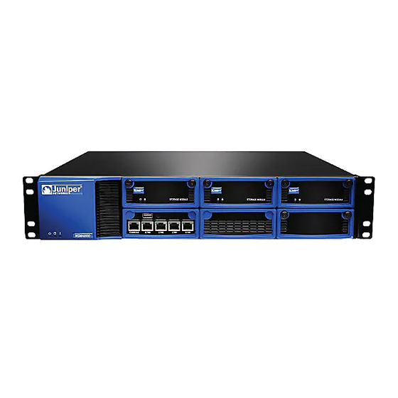
The NSM4000 appliance has a 2-U, rack-mountable chassis with dimensions of 17.81 in. x 17.31 in. x 3.5 in. (45.2 cm x 44 cm x 8.89 cm). The NSM4000 appliance ships with a single AC power supply module; an additional power supply module can be installed in the power supply slot in the rear panel of the appliance. -
Page 18: Chassis Physical Specifications For The Nsm4000 Appliance
Rear Panel of an NSM4000 Appliance on page 6 NSM4000 Ethernet Interfaces Overview on page 7 Chassis Physical Specifications for the NSM4000 Appliance The NSM4000 appliance chassis is a rigid sheet-metal structure that houses the appliance hardware components. Table 3 on page 4 summarizes the physical specifications of the NSM4000 appliance chassis. - Page 19 Table 4: NSM4000 Appliance Front Panel Components Component Description Hard drives The NSM4000 appliance has six hot-swappable 1-TB hard disk drives in a RAID 10 configuration. The hard drives are numbered (0 through 5) as follows: Slot 3 (top left) and Slot 0 (bottom left)
-
Page 20: Rear Panel Of An Nsm4000 Appliance
Hard Disk Activity LED (green), which indicates disk activity Hard Disk Failure LED (red), which indicates disk failure (On) or disk rebuilding (Blinking) Related Rear Panel of an NSM4000 Appliance on page 6 Documentation NSM4000 Ethernet Interfaces Overview on page 7 NSM4000 Appliance Overview on page 3... -
Page 21: Nsm4000 Ethernet Interfaces Overview
Platform GUI. You can access the GUI by using the VIP address of the fabric. eth1—Use the eth1 interface as an administrative interface for an NSM4000 node. Use SSH to access an NSM4000 node through this interface. The eth0 interface and the eth1 interface can be on different subnets. - Page 22 Configure only the eth0 interface. When only Ethernet interface0 (eth0) is used, the NSM4000 nodes in the fabric, the virtual IP (VIP) address of the fabric, and the devices being managed by NSM4000 are on the same subnet. Configure the eth0 and eth3 interfaces.
-
Page 23: Synchronizing Ntp Time Sources To Ensure Consistent Behavior Among
When you configure each NSM4000 appliance with an NTP server, you ensure that, if the first node (which is used to synchronize time for all nodes in the fabric) goes down, all other nodes in the fabric remain synchronized. - Page 24 NSM4000 Appliance Hardware Guide The default system clock for an NSM4000 appliance might not be precise enough for some networks. To ensure time synchronization across all nodes in the fabric, we strongly recommend that you use the following guidelines: Add an NTP server to the first virtual appliance during initial setup.
-
Page 25: Planning For Appliance Installation
PART 2 Planning for Appliance Installation Component Descriptions and Specifications on page 13 Site Preparation on page 21 Mounting Requirements on page 25 Copyright © 2016, Juniper Networks, Inc. - Page 26 NSM4000 Appliance Hardware Guide Copyright © 2016, Juniper Networks, Inc.
-
Page 27: Component Descriptions And Specifications
Specifications Field-Replaceable Units on the NSM4000 Appliance on page 13 AC Power Cord Specifications for the NSM4000 Appliance on page 14 AC Power Supply in the NSM4000 Appliance on page 15 DC Power Supply in the NSM4000 Appliance on page 17... -
Page 28: Ac Power Cord Specifications For The Nsm4000 Appliance
AC Power Cord Specifications for the NSM4000 Appliance The NSM4000 appliance is shipped with an AC power supply module already installed. A power cord suitable for your region is shipped along with the NSM4000 appliance. The coupler is type C13 as described by International Electrotechnical Commission (IEC) standard 60320. -
Page 29: Ac Power Supply In The Nsm4000 Appliance
Documentation AC Power Supply in the NSM4000 Appliance on page 15 Replacing the AC Power Supply Cord on an NSM4000 Appliance on page 112 AC Power Supply in the NSM4000 Appliance An NSM4000 appliance ships with a single AC power supply module, shown in Figure 4 on page 16. - Page 30 NSM4000 Appliance Hardware Guide NOTE: While it is possible to provide redundancy in the NSM4000 appliance using a combination of AC and DC power supply modules, we recommend that you do not provide redundancy in this manner. Instead, use two AC power supply modules or two DC power supply modules if you want to provide redundancy.
-
Page 31: Dc Power Supply In The Nsm4000 Appliance
Replacing the AC Power Supply Module on an NSM4000 Appliance on page 113 DC Power Supply in the NSM4000 Appliance An NSM4000 appliance ships with a single AC power supply module. However, you can use a DC power supply, shown in Figure 5 on page 17, to power the appliance. -
Page 32: Chassis Console Port Pinouts
Documentation Connecting DC Power to the NSM4000 Appliance on page 37 Replacing the DC Power Supply Cable on an NSM4000 Appliance on page 115 Replacing the DC Power Supply Module on an NSM4000 Appliance on page 117 Chassis Console Port Pinouts... - Page 33 Data Set Ready CTS Input Clear to Send Related Connecting an NSM4000 Appliance to a Management Console on page 39 Documentation Connecting an NSM4000 Appliance to the Network on page 40 Front Panel of an NSM4000 Appliance on page 4...
- Page 34 NSM4000 Appliance Hardware Guide Copyright © 2016, Juniper Networks, Inc.
-
Page 35: Site Preparation
CHAPTER 3 Site Preparation General Site Guidelines for the NSM4000 Appliance on page 21 Site Electrical Wiring Guidelines on page 22 Environmental Requirements and Specifications for the NSM4000 Appliance on page 23 General Site Guidelines for the NSM4000 Appliance The following precautions can help you plan an acceptable operating environment for... -
Page 36: Site Electrical Wiring Guidelines
Environmental Requirements and Specifications for the NSM4000 Appliance on Documentation page 23 General Electrical Safety Guidelines and Warnings on page 157 General Safety Guidelines and Warnings on page 135 General Site Guidelines for the NSM4000 Appliance on page 21 Copyright © 2016, Juniper Networks, Inc. -
Page 37: Environmental Requirements And Specifications For The Nsm4000 Appliance
The appliance can be stored safely in the temperature range of –40° F to 158° F (-40° C to 70° C). Related General Safety Guidelines and Warnings on page 135 Documentation General Site Guidelines for the NSM4000 Appliance on page 21 Copyright © 2016, Juniper Networks, Inc. - Page 38 NSM4000 Appliance Hardware Guide Copyright © 2016, Juniper Networks, Inc.
-
Page 39: Mounting Requirements
Tools and Parts Required to Install the NSM4000 Appliance on page 26 NSM4000 Appliance Rack Requirements The NSM4000 appliance can be installed in a rack. Many types of racks are acceptable, including front-mount racks and two-post (telco) racks. Table 15 on page 25 provides the details of requirements for rack size, clearance, airflow, spacing of mounting brackets and flange holes, and connecting to the building structure. -
Page 40: Tools And Parts Required To Install The Nsm4000 Appliance
Mounting the NSM4000 Appliance on page 30 Documentation Rack-Mounting Warnings on page 147 Tools and Parts Required to Install the NSM4000 Appliance on page 26 Tools and Parts Required to Install the NSM4000 Appliance Table 16 on page 26 lists the tools and equipment required for installing and maintaining the NSM4000 appliance. - Page 41 PART 3 Installing and Connecting the NSM4000 Appliance and Appliance Components Installing the Appliance on page 29 Connecting the Appliance on page 35 Performing Initial Configuration on page 41 Configuring NSM from the CLI on page 55 Configuring NSM from the Web Interface on page 63...
- Page 42 NSM4000 Appliance Hardware Guide Copyright © 2016, Juniper Networks, Inc.
-
Page 43: Installing The Appliance
Front-and-Rear-Mounting the NSM4000 Appliance Recessed in a Rack on page 31 Mid-Mounting the NSM4000 Appliance in a Two-Post Rack on page 32 Unpacking the NSM4000 Appliance The NSM4000 appliance is shipped in a cardboard carton along with the items listed in Table 17 on page CAUTION: The NSM4000 appliance is maximally protected inside the shipping carton. -
Page 44: Mounting The Nsm4000 Appliance
NSM4000 Appliance Rack Requirements on page 25 Documentation Mounting the NSM4000 Appliance on page 30 Tools and Parts Required to Install the NSM4000 Appliance on page 26 Mounting the NSM4000 Appliance You can mount the NSM4000 appliance in one of the following ways: Front and rear flush to a rack—Refer... -
Page 45: Front-And-Rear-Mounting The Nsm4000 Appliance Recessed In A Rack
Chapter 5: Installing the Appliance To mount the NSM4000 appliance front and rear flush to a rack: Insert four rack-mount screws on each side of the appliance to secure the front of the chassis to the equipment rack. Slide the rear-mount rail brackets into the backs of the front rails on either side of the... -
Page 46: Mid-Mounting The Nsm4000 Appliance In A Two-Post Rack
NSM4000 Appliance Rack Requirements on page 25 Mid-Mounting the NSM4000 Appliance in a Two-Post Rack on page 32 Tools and Parts Required to Install the NSM4000 Appliance on page 26 Mid-Mounting the NSM4000 Appliance in a Two-Post Rack This option is suitable for a two-post equipment rack. It allows the appliance to be mounted so that there is even clearance on the front and rear of the rack. - Page 47 Front-and-Rear-Mounting the NSM4000 Appliance Flush to a Rack on page 30 Documentation Front-and-Rear-Mounting the NSM4000 Appliance Recessed in a Rack on page 31 NSM4000 Appliance Rack Requirements on page 25 Tools and Parts Required to Install the NSM4000 Appliance on page 26 Copyright © 2016, Juniper Networks, Inc.
- Page 48 NSM4000 Appliance Hardware Guide Copyright © 2016, Juniper Networks, Inc.
-
Page 49: Connecting The Appliance
Connecting AC Power to the NSM4000 Appliance on page 35 Connecting DC Power to the NSM4000 Appliance on page 37 Connecting an NSM4000 Appliance to a Management Console on page 39 Connecting an NSM4000 Appliance to the Network on page 40... - Page 50 If the AC power source outlet has a power switch, set it to the ON position. The NSM4000 appliance starts powering on when you supply power to the power supply module. If the power supply module is correctly installed and functioning normally, the...
-
Page 51: Connecting Dc Power To The Nsm4000 Appliance
Chapter 6: Connecting the Appliance Replacing the AC Power Supply Module on an NSM4000 Appliance on page 113 Connecting DC Power to the NSM4000 Appliance Before connecting the NSM4000 appliance to a DC power source: Ensure that you have read the guidelines in “DC Power Electrical Safety Guidelines”... - Page 52 The grounding terminal is located to the right and above the terminals, as shown in Figure 11 on page Figure 11: DC Power Supply Grounding Connect the grounding lug to the earthing terminal using the screw, as shown in Figure 11 on page Copyright © 2016, Juniper Networks, Inc.
-
Page 53: Connecting An Nsm4000 Appliance To A Management Console
Attach the plastic safety cover. Close the input circuit breaker. The NSM4000 appliance starts powering on when you supply power to the power supply module. If the power supply module is correctly installed and functioning normally, the LED on the power supply module displays green when the power supply module is powering the appliance, and amber when the power supply module is in standby mode (not powering the appliance). -
Page 54: Connecting An Nsm4000 Appliance To The Network
Chassis Console Port Pinouts on page 18 Connecting an NSM4000 Appliance to the Network Although the NSM4000 appliance has four Ethernet interfaces, only two can be used; the other two Ethernet interfaces are reserved for future use. On the NSM4000 appliance, the Ethernet interfaces that can be used are labeled . -
Page 55: Performing Initial Configuration
NSM4000 Appliance Ports on page 52 Booting the NSM4000 Appliance When you first turn on an unconfigured NSM4000 appliance, you need to enter basic network and machine information through the serial console to make your NSM4000 appliance accessible to the network. After entering these settings, you can continue configuring the appliance using the CLI. -
Page 56: Setting Up Your Nsm4000 Appliance
Configuring a Regional Server on page 45 NSM4000 Appliance Ports on page 52 Setting Up Your NSM4000 Appliance This section provides the minimum information necessary to make your NSM4000 appliance active on the network. To log in and set up your NSM4000 appliance:... - Page 57 Chapter 7: Performing Initial Configuration Figure 14: NSM4000 Serial Console Copyright © 2016, Juniper Networks, Inc.
- Page 58 # prompt. Enter the admin password. Enter at the command prompt to configure the NSMXpress settings. nsm_setup Related Booting the NSM4000 Appliance on page 41 Documentation Configuring a Regional Server on page 45 Copyright © 2016, Juniper Networks, Inc.
-
Page 59: Configuring A Regional Server
Chapter 7: Performing Initial Configuration NSM4000 Appliance Ports on page 52 Configuring a Regional Server This section describes the options that are available for reconfiguring the regional server. After you enter at the command prompt, the serial console displays the... -
Page 60: Configuring Settings
Base Install the built-in limited device license for as many as 25 devices. This option is the default. Otherwise, enter the filename of the license file you purchased from Juniper Networks that permits you to manage more than 25 devices. -
Page 61: Configuring High Availability
Menu: Shared Disk—Enter to open a menu to help you configure a shared disk. NSM4000 appliances support shared disks with NFS only. Because of the data-intensive nature of NSM, we recommend gigabit speed links (1000 Mbps) for shared disk usage. -
Page 62: Configuring Advanced Options
The valid range is 00-23. Remote Backup IP—Enter to specify the IP address of the remote backup machine. Backup information is copied to the directory on the remote /var/netscreen/dbbackup Copyright © 2016, Juniper Networks, Inc. -
Page 63: Powering Off The Nsm4000 Appliance
Powering Off Using the WebUI on page 50 Powering Off Using the Appliance Power Switch on page 50 Powering Off Using the Management Console You can power off the NSM4000 appliance from the NSM CLI by using the management console. Copyright © 2016, Juniper Networks, Inc. -
Page 64: Powering Off Using The Webui
Power Supply Module LED turns amber. Powering Off Using the WebUI For information on how to power off the NSM4000 appliance using the WebUI, see “Rebooting or Shutting Down the NSM4000 Appliance” in “Managing System Administration”... - Page 65 Power Supply Module LED turns amber. Related General Electrical Safety Guidelines and Warnings on page 157 Documentation General Safety Guidelines and Warnings on page 135 Installing and Removing NSM4000 Appliance Hardware Components on page 111 Copyright © 2016, Juniper Networks, Inc.
-
Page 66: Nsm4000 Appliance Ports
NSM4000 Appliance Hardware Guide NSM4000 Appliance Ports Table 18 on page 52 provides required port information for the NSM4000 appliance. Table 18: Required Ports on NSM4000 Depends on Direction Port Description Internet Configuration SSH command-line management Web interface for administrator... - Page 67 For more information on ports, refer to the Network and Security Manager Installation Guide. Related Installing an NSM4000 ISO Image on the NSM4000 Appliance Using a USB Drive on Documentation page 97 Setting Up Your NSM4000 Appliance on page 42 Configuring a Regional Server on page 45 Copyright ©...
- Page 68 NSM4000 Appliance Hardware Guide Copyright © 2016, Juniper Networks, Inc.
-
Page 69: Configuring Nsm From The Cli
Navigating the Menus on page 55 Configuring Standard Configuration Options on page 56 Installing the Patch for the NSM4000 License Key File on page 61 Navigating the Menus As you configure NSM on your NSM4000 appliance, the following standard navigational menu options are available to you. -
Page 70: Configuring Standard Configuration Options
(with the exception of any password changes) will not take effect until you apply the changes. Run nsm_setup to access these options on the NSM4000 appliance settings menu: Changing the Password on page 57 Setting Interface Options on page 57... -
Page 71: Changing The Password
Type the new password and press Enter Retype the new password and press Enter Your password is changed and the setup program returns you to the NSM4000 appliance settings menu. Setting Interface Options The NSM4000 appliance has four ethernet ports labeled , and . -
Page 72: Setting Routing Options
2 for 100 Mbps and go to the next step 3 for 1000 Mbps and go to the next step Enter 1 for full duplex or 2 for half duplex, and then return to the NSM4000 appliance Settings menu. Setting Routing Options To set or modify routing options: On the NSM4000 appliance Settings menu, enter 3 at the prompt. -
Page 73: Setting The System Time
To change time options: On the NSM4000 appliance Settings menu, enter 6 at the prompt. Enter 1 to change the time zone. Follow the prompts to find the time zone you want based on the options listed earlier. -
Page 74: Updating System Security
Before you configure the regional server, the NSM4000 appliance opens the Apply Change submenu. If you quit out of a menu after making changes, he NSM4000 appliance also opens this screen and prompts you to save your changes. Updates are enabled by default. -
Page 75: Installing The Patch For The Nsm4000 License Key File
This section describes the procedure for installing the patch for the NSM4000 license key file. The serial number of the NSM4000 appliance has a new format. In the 2012.2R7, 2012.2R8 and 2012.2R9 releases, you need to install a patch that enables NSM to identify the new format of the NSM4000 appliance serial number. - Page 76 GUI server. For additional details about NSM licensing, see the Network and Security Manager Installation Guide. Related Navigating the Menus on page 55 Documentation Configuring Standard Configuration Options on page 56 Copyright © 2016, Juniper Networks, Inc.
-
Page 77: Configuring Nsm From The Web Interface
Changing the NSM Management IP on page 67 Scheduling Security Updates on page 67 Changing the Super User Password To change the super user password, select > NSM Administration NSM Super User . See Figure 15 on page Password Copyright © 2016, Juniper Networks, Inc. -
Page 78: Downloading Nsm Mibs (Regional Server Only)
IP address, if it is not the local host. Exporting Device Logs (Regional Server Only) To export device logs, select > . See NSM Administration Export Device Logs Figure 18 on page Copyright © 2016, Juniper Networks, Inc. -
Page 79: Generating Reports (Regional Server Only)
Generate Reports Figure 19 on page Figure 19: Generate Reports NOTE: The user is an NSM administrator and not an NSM4000 appliance user. Enter a username as domain/user, such as global/super. Modifying NSM Configuration Files To manually edit the files, select GuiSrv.cfg... -
Page 80: Backing Up The Nsm Database
NSM4000 Appliance Hardware Guide Figure 20: NSM Configuration Files NOTE: If you subsequently change the NSM4000 appliance configuration by using the nsm-setup utility, all manual changes to the configuration files are lost. Backing Up the NSM Database To configure backups of the NSM database, select >... -
Page 81: Changing The Nsm Management Ip
To schedule security updates, select > NSM Administration Schedule Security Updates Figure 23 on page Figure 23: Schedule Security Updates Related Setting Up Your NSM4000 Appliance on page 42 Documentation Managing System Administration on page 68 Copyright © 2016, Juniper Networks, Inc. -
Page 82: Managing System Administration
Use the options on the System Administration menu to perform the tasks described in the following sections: Rebooting or Shutting Down the NSM4000 Appliance on page 68 Changing the User Password on page 68 Configuring the Network on page 69... -
Page 83: Configuring The Network
Use this option to manage the network interfaces. See Figure 27 on page Figure 27: Network Interfaces Routing and Gateways Use this option to configure and manage routes and gateways. See Figure 28 on page Copyright © 2016, Juniper Networks, Inc. -
Page 84: Hostnames And Dns Clients
Use this option to manage host addresses. See Figure 30 on page Figure 30: Host Address Managing RADIUS Servers The NSM4000 appliance WebUI supports authentication of users defined in the RADIUS servers, in addition to authentication of locally defined admin users. Copyright © 2016, Juniper Networks, Inc. -
Page 85: Adding A Radius Server
Chapter 9: Configuring NSM from the Web Interface When a user logs in to the NSM4000 appliance using the WebUI, the software first checks the UNIX user database and then the WebUI user database to authenticate the user. If the user is not a locally defined admin user, the software contacts the RADIUS servers added to the RADIUS server list in the Web UI to authenticate the user. -
Page 86: Changing The Priority Of Radius Servers
Name: The name of the user to be authenticated by the RADIUS server Server address: The IP address or the hostname of the RADIUS server. Shared secret: The shared secret the NSM4000 appliance and the RADIUS server use for secure authentication. -
Page 87: Deleting A Radius Server
NSM4000 appliance. You configure SNMP on the NSM4000 appliances with access credentials for either SNMP v2c or SNMP v3. NSM4000 appliances support read-only access to the System Descriptor (sysDescr) and Host Resource MIB. Copyright © 2016, Juniper Networks, Inc. -
Page 88: Snmp Configuration
If you selected SNMP v3, enter a username and password. The password must be at least 8 characters long. The NSM4000 appliances implement a single username and password, which is effective only for SNMP communication and is not related to any other username and password used on the NSM4000 appliance. -
Page 89: Snmp System Information
SNMP Monitoring Select the SNMP Traps tab, which is shown in Figure 36 on page Figure 36: Configuring SNMP Traps In the Manager IP field, enter the IP address of the SNMP management server. Copyright © 2016, Juniper Networks, Inc. -
Page 90: Forwarding Syslog Messages
Adding and Configuring Syslog Receivers on page 78 Editing Syslog Receiver Configurations on page 80 Deleting Syslog Receivers on page 80 Viewing Syslog Receivers To view the syslog receivers configured on your NSM4000 appliance, follow these steps: Select System Administration >... - Page 91 The device server logs configured to be sent to this receiver. GUI Server The GUI server logs configured to be sent to this receiver. HA Server The HA server logs configured to be sent to this receiver. Copyright © 2016, Juniper Networks, Inc.
-
Page 92: Adding And Configuring Syslog Receivers
HA server log. The syslog facility is a field included in the syslog message to help identify the data source. Click Save Click Add new Receiver The Syslog Receiver configuration window appears, as shown in Figure 38 on page Copyright © 2016, Juniper Networks, Inc. - Page 93 NSM. In the IP field, enter the IP address of the syslog receiver. In the Transport field, select the type of syslog receiver: Select for basic syslog implementations. Select for rsyslog or syslog-NG implementations. Copyright © 2016, Juniper Networks, Inc.
-
Page 94: Editing Syslog Receiver Configurations
In the Syslog Receivers window, check the box next to each syslog receiver you want to delete. Click Delete selected receivers The NSM4000 appliance deletes the selected syslog receivers and any secure tunnels configured for their use. Changing the System Time To set the system time, select >... -
Page 95: Managing Users
WebUI. You can create a user in the WebUI and associate the user to a predefined user profile. You can also map a user created in the NSM4000 appliance OS to a predefined user profile in the WebUI. However, this user profile is only applicable to the local OS user in the WebUI. -
Page 96: Deleting A User
From the User Profile drop-down list box, select the user profile you want to associate with the local user in the WebUI. Click . The NSM4000 Users dialog box appears with the new NSM4000 Submit appliance user listed. To create a WebUI user: Select >... -
Page 97: Editing User Attributes
System Administration User Management appears, with all the NSM4000 appliance users listed. Click on the name of the user whose attributes you want to edit. The Edit NSM4000 Users dialog box appears. Edit the parameters you want to change and click . - Page 98 NSM4000 Appliance Hardware Guide Table 20: NSM4000 Appliance WebUI User Profiles and Permissions (continued) NSM4000 Appliance System Network Guest Modules Administrator Administrator Operator User System Time System Update User Management WebUI Configuration NSM Administration Change NSM Super User Password Download NSM MIBs...
-
Page 99: Configuring The Web Interface
Chapter 9: Configuring NSM from the Web Interface Configuring the Web Interface To specify which NSM client computers can access the NSM4000 appliance through the Web interface, select System Administration > WebUI Configuration . The Allowed IP Addresses window appears as shown in... -
Page 100: Cpu
Select Tile all graphs to display all the statistical graphs for the system in one window. Related Setting Up Your NSM4000 Appliance on page 42 Documentation Managing NSM Administration on page 63 Managing System Administration on page 68 Viewing System Information on page 87... -
Page 101: Viewing System Information
CPU load and memory use, as shown in Figure 43 on page Figure 43: System Information Related Managing NSM Administration on page 63 Documentation Managing System Administration on page 68 Viewing System Statistics on page 85 Copyright © 2016, Juniper Networks, Inc. - Page 102 NSM4000 Appliance Hardware Guide Copyright © 2016, Juniper Networks, Inc.
-
Page 103: Hardware Troubleshooting
PART 4 Hardware Troubleshooting Troubleshooting the NSM4000 Appliance on page 91 Copyright © 2016, Juniper Networks, Inc. - Page 104 NSM4000 Appliance Hardware Guide Copyright © 2016, Juniper Networks, Inc.
-
Page 105: Troubleshooting The Nsm4000 Appliance
Installing an NSM4000 ISO Image on the NSM4000 Appliance Using a USB Drive on page 97 Troubleshooting NSM4000 Ethernet Interface eth0 Connectivity Purpose If you have connectivity issues with the NSM4000 Ethernet interface eth0, you can use this procedure to troubleshoot the connectivity issues. Action Before you begin: Connect a management device (PC or laptop) to the appliance using the management console and power on both the appliance and the management device. -
Page 106: Auditing User Operations
Auditing User Operations on page 92 Reviewing Error Logs on page 93 Checking Network Routes, Addresses, and Connections Using TCP/IP Network Utilities on page 94 Installing an NSM4000 ISO Image on the NSM4000 Appliance Using a USB Drive on page 97 Auditing User Operations Purpose You can audit all user operations performed in an NSM4000 appliance. -
Page 107: Reviewing Error Logs
Documentation Reviewing Error Logs on page 93 Checking Network Routes, Addresses, and Connections Using TCP/IP Network Utilities on page 94 Installing an NSM4000 ISO Image on the NSM4000 Appliance Using a USB Drive on page 97 Reviewing Error Logs Purpose To review error logs, select >... -
Page 108: Checking Network Routes, Addresses, And Connections Using Tcp/Ip Network
Auditing User Operations on page 92 Checking Network Routes, Addresses, and Connections Using TCP/IP Network Utilities on page 94 Installing an NSM4000 ISO Image on the NSM4000 Appliance Using a USB Drive on page 97 Checking Network Routes, Addresses, and Connections Using TCP/IP Network Utilities To access basic network utilities for TCP/IP Networking, select >... -
Page 109: Ping
Lookup on page 96 IP Subnet Calculator on page 97 Ping Ping is a tool for checking network connectivity. The NSM4000 appliance prompts you with questions so you can focus your search. Figure 49 on page 95 shows an example. -
Page 110: Traceroute
97). The query type drop-down list contains several types of records found in the DNS database. Enter a name server or select the default. If you choose the default, nslookup uses the server on which the NSM4000 appliance is installed. -
Page 111: Ip Subnet Calculator
Auditing User Operations on page 92 Reviewing Error Logs on page 93 Installing an NSM4000 ISO Image on the NSM4000 Appliance Using a USB Drive on page 97 Installing an NSM4000 ISO Image on the NSM4000 Appliance Using a USB Drive You can install an NSM4000 ISO image on the NSM4000 appliance using a standard USB 2.0 and USB 3.0 drive. -
Page 112: Downloading The Nsm4000 Iso Image From The Juniper Networks Support
In some cases, the Delete key on a PC keyboard does not send a DEL or Control-? character. You must ensure that the terminal utility that you are using to connect to the NSM4000 appliance maps a key to the DEL or Control-? character. Typically, this is accomplished by configuring the terminal utility to send a DEL or Control-? character when the Backspace key on the keyboard is pressed. -
Page 113: Creating A Bootable Usb Drive
Chapter 10: Troubleshooting the NSM4000 Appliance Downloading the NSM4000 ISO Image from the Juniper Networks Support Site This section provides the information necessary to download the NSM4000 ISO image from the Juniper Networks support site. To download the NSM4000 ISO image: Plug the USB drive to the USB port of a laptop or PC that is connected to the Internet. - Page 114 On that same line, to the right of the drop-down menu, click the CD-ROM ISO Image icon. Select the NSM4000 ISO image file that you want to copy to the USB drive. Click Start Click in the Warning dialog box to format the USB drive and copy the NSM4000 ISO image.
- Page 115 Chapter 10: Troubleshooting the NSM4000 Appliance Figure 54: Rufus Warning Dialog Box A progress bar in the Rufus window displays the status; if the start operation is successful, a message is displayed. Click Close to exit the Rufus window. Figure 55 on page 102 displays the Rufus window as it appears after you have successfully created a bootable USB drive.
-
Page 116: Ensuring That The Nsm4000 Appliance's Bios Boots From The Usb
USB drive that contains a copy of the NSM4000 ISO image file. To boot the NSM4000 appliance from the USB drive: Plug the USB drive into the USB port of the NSM4000 appliance on which you want to install the software image. -
Page 117: Installing The Nsm4000 Iso Image On The Nsm4000 Appliance
If you are successful in accessing the BIOS setup, the boot menu appears after about one minute. Ensure that the USB boot is at the top of the NSM4000 appliance boot priority order. If the USB label is not at the top of the list: Use the down arrow to select the USB label and use the + key to move the entry to the top of the list. - Page 118 NOTE: Because the NSM4000 appliance boot order was changed earlier in this procedure, the NSM4000 appliance will try to boot from the USB drive before choosing the next option. You can revert to boot from the local disk using the method explained in “Ensuring that the NSM4000...
- Page 119 Juniper NSMXpress Appliance NSM 2012.2R7 NSM4000.juniper.net login: For information on how to configure the basic settings for the NSM4000 appliance before you can use it to manage devices, see “Setting Up Your NSM4000 Appliance” on page 42 “Configuring a Regional Server” on page...
- Page 120 NSM4000 Appliance Hardware Guide Copyright © 2016, Juniper Networks, Inc.
-
Page 121: Hardware Maintenance And Replacement
PART 5 Hardware Maintenance and Replacement Maintaining the Hardware on page 109 Replacing Hardware Components on page 111 Copyright © 2016, Juniper Networks, Inc. - Page 122 NSM4000 Appliance Hardware Guide Copyright © 2016, Juniper Networks, Inc.
-
Page 123: Maintaining The Hardware
Inspect the site to ensure that the grounding and power cables connected to the NSM4000 appliance are securely in place and that there is no moisture accumulating near the appliance. Ensure that the power and grounding cables are arranged so that they do not obstruct access to other components. - Page 124 NSM4000 Appliance Hardware Guide Copyright © 2016, Juniper Networks, Inc.
-
Page 125: Replacing Hardware Components
Replacing Hardware Components Installing and Removing NSM4000 Appliance Hardware Components on page 111 Replacing the AC Power Supply Cord on an NSM4000 Appliance on page 112 Replacing the AC Power Supply Module on an NSM4000 Appliance on page 113 Replacing the DC Power Supply Cable on an NSM4000 Appliance on page 115... -
Page 126: Replacing The Ac Power Supply Cord On An Nsm4000 Appliance
Field-Replaceable Units on the NSM4000 Appliance on page 13 Replacing the AC Power Supply Cord on an NSM4000 Appliance NOTE: If only one power supply module is installed in your NSM4000 appliance, you must power off the appliance before replacing the power supply cord. -
Page 127: Replacing The Ac Power Supply Module On An Nsm4000 Appliance
Verify that the power cord does not block the air exhaust and access to device components, or drape where people could trip on it. The NSM4000 appliance starts powering on when you supply power to the power supply module. If the power supply cord is correctly installed, the LED on the power supply module displays green when the power supply module is powering the appliance, and amber when the power supply module is in standby mode (not powering the appliance). -
Page 128: Removing The Ac Power Supply Module
NSM4000 Appliance Hardware Guide NOTE: If only one power supply module is installed in your NSM4000 appliance, you must power off the appliance before removing the power supply module. This topic contains the following sections: Removing the AC Power Supply Module on page 114... -
Page 129: Installing The Ac Power Supply Module
If the appliance is not powered on, power on the appliance by pressing the switch on the rear panel, next to the power supply module. The NSM4000 appliance starts powering on when you supply power to the power supply module. If the power supply module is correctly installed and functioning... -
Page 130: Removing The Dc Power Supply Cable
Phillips (+) screwdriver, number 2 An antistatic bag or an antistatic mat NOTE: If only one power supply module is installed in your NSM4000 appliance, you must power off the appliance before removing the power supply cable. This topic contains the following sections:... -
Page 131: Connecting The Dc Power Supply Cable
Switch on the external circuit breakers, if they are present, for all the cables attached to the power supply. The NSM4000 appliance starts powering on when you supply power to the power supply module. If the power supply module is correctly installed and functioning normally, the... -
Page 132: Removing The Dc Power Supply Module
Installing a DC Power Supply Module on page 119 Removing the DC Power Supply Module To remove the DC power supply module from an NSM4000 appliance: Switch off the dedicated facility circuit breaker for the power supply module being removed. -
Page 133: Installing A Dc Power Supply Module
Documentation Field-Replaceable Units on the NSM4000 Appliance on page 13 Replacing the DC Power Supply Cable on an NSM4000 Appliance on page 115 Replacing the Fan on an NSM4000 Appliance The NSM4000 appliance ships with two field-replaceable fans that are hot-swappable. -
Page 134: Removing The Fan
2—Hard Disk Activity LED CAUTION: The NSM4000 appliance should not run on one fan for an extended period of time. Failed fans should be replaced as soon as possible. Ensure that you have the following parts and tools available to remove the fan from the... -
Page 135: Installing The Fan
Installing and Removing NSM4000 Appliance Hardware Components on page 111 Replacing the Hard Disk on an NSM4000 Appliance The NSM4000 appliance ships with six hard disk drives in a RAID 10 array configuration. The hot-swappable drives are externally accessible in field-replaceable trays. You can remove and replace a hard disk without powering off the appliance or disrupting any functions performed by the appliance. -
Page 136: Removing The Hard Disk
Installing the Hard Disk on page 123 Removing the Hard Disk To remove a hard disk from the NSM4000 appliance: Place the antistatic bag or antistatic mat on a flat, stable surface. (Optional) Attach an ESD grounding strap to your bare wrist, and connect the strap to an external ESD point. -
Page 137: Installing The Hard Disk
Chapter 12: Replacing Hardware Components Figure 66: Removing a Hard Disk Installing the Hard Disk To install a hard disk in the NSM4000 appliance: (Optional) Attach an ESD grounding strap to your bare wrist, and connect the strap to an external ESD point. - Page 138 NSM4000 Appliance Hardware Guide Related Field-Replaceable Units on the NSM4000 Appliance on page 13 Documentation Installing and Removing NSM4000 Appliance Hardware Components on page 111 Copyright © 2016, Juniper Networks, Inc.
-
Page 139: Returning Hardware
PART 6 Returning Hardware Returning the Appliance or Appliance Components on page 127 Copyright © 2016, Juniper Networks, Inc. - Page 140 NSM4000 Appliance Hardware Guide Copyright © 2016, Juniper Networks, Inc.
-
Page 141: Returning The Appliance Or Appliance Components
Returning the Appliance or Appliance Components Returning an NSM4000 Appliance or Component for Repair or Replacement on page 127 Locating the Serial Number on an NSM4000 Appliance or Component on page 128 Contacting Customer Support to Obtain Return Materials Authorization for NSM4000... -
Page 142: Locating The Serial Number On An Nsm4000 Appliance Or Component
If you do not have access to dmidecode --type 1 the NSM4000 CLI, you can find the serial number on the ID label present on the physical appliance or component. NOTE: To find the serial number on the physical appliance component, you need to remove the component from the appliance chassis, for which you must have the required parts and tools available. -
Page 143: Appliance
Locating the Chassis Serial Number ID Label on an NSM4000 Appliance The serial number of an NSM4000 appliance is displayed on the appliance chassis. To locate the serial number of the NSM4000 appliance, see the label at the rear panel of the chassis, as shown in Figure 68 on page 129. -
Page 144: Packing An Nsm4000 Appliance Or Component For Shipping
Packing an NSM4000 Appliance or Component for Shipping If you are returning an NSM4000 appliance or component (field-replaceable unit [FRU]) to Juniper Networks for repair or replacement, pack the item as described in this topic. Before you begin packing the appliance or component: Obtain a Return Materials Authorization (RMA) number for the appliance or the component. -
Page 145: Packing An Nsm4000 Appliance For Shipping
Packing Components of the NSM4000 Appliance for Shipping on page 131 Packing an NSM4000 Appliance for Shipping If you need to transport the NSM4000 appliance to another location or return the appliance to Juniper Networks, you need to pack the appliance securely in its original packaging to prevent damage during transportation. - Page 146 Write the RMA number on the exterior of the box to ensure proper tracking. Related Contacting Customer Support to Obtain Return Materials Authorization for NSM4000 Documentation Appliances on page 129 Locating the Serial Number on an NSM4000 Appliance or Component on page 128 Copyright © 2016, Juniper Networks, Inc.
-
Page 147: Safety Information
PART 7 Safety Information General Safety Information on page 135 Radiation and Laser Warnings on page 141 Installation and Maintenance Safety Information on page 145 Power and Electrical Safety Information on page 157 Copyright © 2016, Juniper Networks, Inc. - Page 148 NSM4000 Appliance Hardware Guide Copyright © 2016, Juniper Networks, Inc.
-
Page 149: General Safety Information
Never attempt to lift an object that is too heavy for one person to handle. Never install or manipulate wiring during electrical storms. Never install electrical jacks in wet locations unless the jacks are specifically designed for wet environments. Operate the appliance only when it is properly grounded. Copyright © 2016, Juniper Networks, Inc. -
Page 150: Definitions Of Safety Warning Levels
This symbol alerts you to the risk of personal injury from a laser. WARNING: This symbol means danger. You are in a situation that could cause bodily injury. Before you work on any equipment, be aware of the hazards Copyright © 2016, Juniper Networks, Inc. - Page 151 Varning! Denna varningssymbol signalerar fara. Du befinner dig i en situation som kan leda till personskada. Innan du utför arbete på någon utrustning Copyright © 2016, Juniper Networks, Inc.
-
Page 152: Fire Safety Requirements
Grounded Equipment Warning on page 151 Installation Instructions Warning on page 145 Laser and LED Safety Guidelines and Warnings for the NSM4000 Appliance on page 141 Maintenance and Operational Safety Guidelines and Warnings on page 151 Warning Statement for Norway and Sweden on page 140... -
Page 153: Qualified Personnel Warning
NOTE: To keep warranties effective, do not use a dry chemical fire extinguisher to control a fire at or near an NSM4000 appliance or other network device provided by Juniper Networks. If a dry chemical fire extinguisher is used, the unit is no longer eligible for coverage under a service agreement. -
Page 154: Warning Statement For Norway And Sweden
Advarsel Apparatet skal kobles til en jordet stikkontakt. Varning! Apparaten skall anslutas till jordat nätuttag. Related General Safety Guidelines and Warnings on page 135 Documentation Definitions of Safety Warning Levels on page 136 Copyright © 2016, Juniper Networks, Inc. -
Page 155: Radiation And Laser Warnings
CHAPTER 15 Radiation and Laser Warnings Laser and LED Safety Guidelines and Warnings for the NSM4000 Appliance on page 141 Radiation from Open Port Apertures Warning on page 144 Laser and LED Safety Guidelines and Warnings for the NSM4000 Appliance... -
Page 156: Class 1 Led Product Warning
Aviso Produto de classe 1 com LED. ¡Atención! Aviso sobre producto LED de Clase 1. Varning! Lysdiodprodukt av klass 1. Laser Beam Warning WARNING: Do not stare into the laser beam or view it directly with optical instruments. Copyright © 2016, Juniper Networks, Inc. - Page 157 Related General Safety Guidelines and Warnings on page 135 Documentation Grounded Equipment Warning on page 151 Installation Instructions Warning on page 145 Radiation from Open Port Apertures Warning on page 144 Copyright © 2016, Juniper Networks, Inc.
-
Page 158: Radiation From Open Port Apertures Warning
General Safety Guidelines and Warnings on page 135 Documentation Grounded Equipment Warning on page 151 Installation Instructions Warning on page 145 Laser and LED Safety Guidelines and Warnings for the NSM4000 Appliance on page 141 Copyright © 2016, Juniper Networks, Inc. -
Page 159: Installation And Maintenance Safety Information
CHAPTER 16 Installation and Maintenance Safety Information Installation Instructions Warning on page 145 Chassis Lifting Guidelines for the NSM4000 Appliance on page 146 Ramp Warning on page 146 Rack-Mounting Warnings on page 147 Grounded Equipment Warning on page 151 Maintenance and Operational Safety Guidelines and Warnings on page 151... -
Page 160: Chassis Lifting Guidelines For The Nsm4000 Appliance
Related General Safety Guidelines and Warnings on page 135 Documentation Laser and LED Safety Guidelines and Warnings for the NSM4000 Appliance on page 141 Grounded Equipment Warning on page 151 Connecting AC Power to the NSM4000 Appliance on page 35... -
Page 161: Rack-Mounting Warnings
De onderstaande richtlijnen worden verstrekt om uw veiligheid te verzekeren: De Juniper Networks device moet in een stellage worden geïnstalleerd die aan een bouwsel is verankerd. Dit toestel dient onderaan in het rek gemonteerd te worden als het toestel het enige in het rek is. - Page 162 Les directives ci-dessous sont destinées à assurer la protection du personnel: Le rack sur lequel est monté le Juniper Networks device doit être fixé à la structure du bâtiment. Si cette unité constitue la seule unité montée en casier, elle doit être placée dans le bas.
- Page 163 Le seguenti direttive vengono fornite per garantire la sicurezza personale: Il Juniper Networks device deve essere installato in un telaio, il quale deve essere fissato alla struttura dell'edificio. Questa unità deve venire montata sul fondo del supporto, se si tratta dell'unica unità...
- Page 164 Para garantizar su seguridad, proceda según las siguientes instrucciones: El Juniper Networks device debe instalarse en un bastidor fijado a la estructura del edificio. Colocar el equipo en la parte inferior del bastidor, cuando sea la única unidad en el mismo.
-
Page 165: Grounded Equipment Warning
Chapter 16: Installation and Maintenance Safety Information Mounting the NSM4000 Appliance on page 30 Grounded Equipment Warning WARNING: The device is intended to be grounded. During normal use, ensure that you have connected earth ground to the chassis. Waarschuwing Deze apparatuur hoort geaard te worden Zorg dat de host-computer tijdens normaal gebruik met aarde is verbonden. -
Page 166: Battery Handling Warning
Desechar las baterías gastadas según las instrucciones del fabricante. Varning! Explosionsfara vid felaktigt batteribyte. Ersätt endast batteriet med samma batterityp som rekommenderas av tillverkaren eller motsvarande. Följ tillverkarens anvisningar vid kassering av använda batterier. Copyright © 2016, Juniper Networks, Inc. -
Page 167: Jewelry Removal Warning
à terra, podendo causar queimaduras graves ou ficarem soldados aos terminais. ¡Atención! Antes de operar sobre equipos conectados a líneas de alimentación, quitarse las joyas (incluidos anillos, collares y relojes). Los Copyright © 2016, Juniper Networks, Inc. -
Page 168: Lightning Activity Warning
To prevent the device from overheating, do not operate it in an area that exceeds the maximum recommended ambient temperature of 104° F (40° C) for network devices of Juniper Networks. To prevent airflow Copyright © 2016, Juniper Networks, Inc. - Page 169 6 in. (15.2 cm) of clearance around the ventilation openings. Waarschuwing Om te voorkomen dat welke device van de Juniper Networks router dan ook oververhit raakt, dient u deze niet te bedienen op een plaats waar de maximale aanbevolen omgevingstemperatuur van 40° C wordt overschreden.
-
Page 170: Product Disposal Warning
General Safety Guidelines and Warnings on page 135 Grounded Equipment Warning on page 151 Installation Instructions Warning on page 145 Laser and LED Safety Guidelines and Warnings for the NSM4000 Appliance on page 141 Copyright © 2016, Juniper Networks, Inc. -
Page 171: Power And Electrical Safety Information
(ESD) grounding strap to an ESD point and place the other end of the strap around your bare wrist. Failure to use an ESD grounding strap could result in damage to the device. Copyright © 2016, Juniper Networks, Inc. -
Page 172: Preventing Electrostatic Discharge Damage
Observe the following guidelines to minimize the potential for electrostatic discharge (ESD) damage, which can cause intermittent or complete component failures: Copyright © 2016, Juniper Networks, Inc. - Page 173 Related General Electrical Safety Guidelines and Warnings on page 157 Documentation General Safety Guidelines and Warnings on page 135 Copyright © 2016, Juniper Networks, Inc.
-
Page 174: Ac Power Electrical Safety Guidelines
General Electrical Safety Guidelines and Warnings on page 157 Documentation General Safety Guidelines and Warnings on page 135 Multiple Power Supplies Disconnection Warning on page 168 Connecting AC Power to the NSM4000 Appliance on page 35 Copyright © 2016, Juniper Networks, Inc. -
Page 175: Ac Power Disconnection Warning
Related AC Power Electrical Safety Guidelines on page 160 Documentation General Electrical Safety Guidelines and Warnings on page 157 General Safety Guidelines and Warnings on page 135 Copyright © 2016, Juniper Networks, Inc. -
Page 176: Dc Power Electrical Safety Guidelines
DC Power Grounding Requirements and Warning on page 164 DC Power Wiring Sequence Warning on page 165 DC Power Wiring Terminations Warning on page 167 General Electrical Safety Guidelines and Warnings on page 157 General Safety Guidelines and Warnings on page 135 Copyright © 2016, Juniper Networks, Inc. -
Page 177: Dc Power Disconnection Warning
Chapter 17: Power and Electrical Safety Information Multiple Power Supplies Disconnection Warning on page 168 Connecting DC Power to the NSM4000 Appliance on page 37 DC Power Disconnection Warning WARNING: Before performing any of the DC power procedures, ensure that power is removed from the DC circuit. -
Page 178: Dc Power Grounding Requirements And Warning
Waarschuwing Bij de installatie van het toestel moet de aardverbinding altijd het eerste worden gemaakt en het laatste worden losgemaakt. Varoitus Laitetta asennettaessa on maahan yhdistäminen aina tehtävä ensiksi ja maadoituksen irti kytkeminen viimeiseksi. Copyright © 2016, Juniper Networks, Inc. -
Page 179: Dc Power Wiring Sequence Warning
–45 naar –60 V, +RTN naar +RTN, aarde naar aarde. Varoitus Oikea yhdistettava kytkentajarjestys on maajohto maajohtoon, +RTN varten +RTN, –45 V varten –60 V. Oikea irrotettava kytkentajarjestys on –45 V varten –60 V, +RTN varten +RTN, maajohto maajohtoon. Copyright © 2016, Juniper Networks, Inc. - Page 180 Varning! Korrekt kopplingssekvens ar jord till jord, +RTN till +RTN, –45 V till –60 V. Korrekt kopplas kopplingssekvens ar –45 V till –60 V, +RTN till +RTN, jord till jord. Related DC Power Electrical Safety Guidelines on page 162 Documentation Copyright © 2016, Juniper Networks, Inc.
-
Page 181: Dc Power Wiring Terminations Warning
Advarsel Hvis det er nødvendig med flertrådede ledninger, brukes godkjente ledningsavslutninger, som for eksempel lukket sløyfe eller spadetype med oppoverbøyde kabelsko. Disse avslutningene skal ha riktig størrelse i forhold til ledningene, og skal klemme sammen både isolasjonen og lederen. Copyright © 2016, Juniper Networks, Inc. -
Page 182: Multiple Power Supplies Disconnection Warning
AC Power Electrical Safety Guidelines on page 160 Documentation DC Power Electrical Safety Guidelines on page 162 General Electrical Safety Guidelines and Warnings on page 157 General Safety Guidelines and Warnings on page 135 Copyright © 2016, Juniper Networks, Inc. -
Page 183: Tn Power Warning
If possible, send another person to get medical aid. Otherwise, assess the condition of the victim, then call for help. Related AC Power Electrical Safety Guidelines on page 160 Documentation DC Power Electrical Safety Guidelines on page 162 Copyright © 2016, Juniper Networks, Inc. - Page 184 NSM4000 Appliance Hardware Guide General Electrical Safety Guidelines and Warnings on page 157 General Safety Guidelines and Warnings on page 135 Copyright © 2016, Juniper Networks, Inc.
-
Page 185: Compliance Information
PART 8 Compliance Information Compliance Information on page 173 Copyright © 2016, Juniper Networks, Inc. - Page 186 NSM4000 Appliance Hardware Guide Copyright © 2016, Juniper Networks, Inc.
-
Page 187: Compliance Information
Compliance Information Agency Approvals for the NSM4000 Appliance on page 173 Compliance Statements for EMC Requirements for the NSM4000 Appliance on page 174 Compliance Statements for Acoustic Noise for the NSM4000 Appliance on page 176 Agency Approvals for the NSM4000 Appliance... -
Page 188: Compliance Statements For Emc Requirements For The Nsm4000 Appliance
EN 61000-4-6 Low Frequency Common Immunity EN 61000-4-11 Voltage Dips and Sags Related Compliance Statements for EMC Requirements for the NSM4000 Appliance on page 174 Documentation Compliance Statements for Acoustic Noise for the NSM4000 Appliance on page 176 Compliance Statements for EMC Requirements for the NSM4000 Appliance... -
Page 189: European Community
This equipment generates, uses, and can radiate radio frequency energy and, if not installed and used in accordance with the instruction manual, Copyright © 2016, Juniper Networks, Inc. -
Page 190: Fcc Part 15 Statement
Related Agency Approvals for the NSM4000 Appliance on page 173 Documentation Compliance Statements for Acoustic Noise for the NSM4000 Appliance on page 176 Compliance Statements for Acoustic Noise for the NSM4000 Appliance This topic applies to the NSM4000 appliance. Maschinenlärminformations-Verordnung - 3. GPSGV, der höchste Schalldruckpegel beträgt 70 dB(A) oder weniger gemäss EN ISO 7779... -
Page 191: Index
PART 9 Index Index on page 179 Copyright © 2016, Juniper Networks, Inc. - Page 192 NSM4000 Appliance Hardware Guide Copyright © 2016, Juniper Networks, Inc.
-
Page 193: Index
DC power connecting.................37 battery specifications..............17 handling................152 DC power supply braces, in configuration statements........xi connecting.................37 brackets angle, in syntax descriptions........xi square, in configuration statements......xi Copyright © 2016, Juniper Networks, Inc. - Page 194 Class 1 product warning..........141 removing................120 safety guidelines............141 replacing................119 LEDs fault monitoring and performance monitoring appliance................4 node....................7 chassis..................4 field-replaceable units............13 Class 1 product warning..........142 See also FRUs Ethernet................4 font conventions................x hard drive................4 front panel...................4 LAN..................4 Copyright © 2016, Juniper Networks, Inc.
- Page 195 DC power disconnection...........163 serial number..............129 DC power wiring sequence........165 unpacking.................29 DC power wiring terminations.........167 NSM4000 appliance serial number, finding electrical................157 using NSM4000 CLI............128 electrical safety............160 using shell...............128 electrostatic discharge damage......158 NSM4000 components fire safety.................138 returning..............127, general................135...
- Page 196 DC power wiring terminations.........167 earthed mains socket (Norway and Sweden only)................140 electrical................157 electrical safey..............160 fire safety.................138 general................135 grounded equipment...........151 installation instructions..........145 jewelry removal.............153 laser and LED..............141 lightning activity............154 maintenance and operational........151 multiple power supplies disconnection....168 Copyright © 2016, Juniper Networks, Inc.