
Related Manuals for Siemens FDCW241


Summary of Contents for Siemens FDCW241
- Page 1 FDCW241 Radio gateway Technical Manual Building Technologies A6V10227639_k_en_-- 2016-11-28 Control Products and Systems...
- Page 2 Issued by: Siemens Switzerland Ltd. Building Technologies Division International Headquarters Gubelstrasse 22 CH-6301 Zug Tel. +41 41 724-2424 www.siemens.com/buildingtechnologies Edition: 2016-11-28 Document ID: A6V10227639_k_en_-- © Siemens Switzerland Ltd, 2011 2 | 62 Building Technologies A6V10227639_k_en_-- Fire Safety 2016-11-28...
-
Page 3: Table Of Contents
Table of contents About this document ................5 Applicable documents ................. 7 Download center ..................7 Technical terms and abbreviations .............. 7 Revision history ..................8 Safety ....................10 Safety instructions ..................10 Safety regulations for the method of operation ...........12 Standards and directives complied with............14 Release Notes ...................14 Structure and function ................. - Page 4 Connecting the radio cell to the detector line ....... 48 Replacing the radio gateway and transferring data ........49 7.5.1 Replacing the radio gateway FDCW241 ........49 Firmware update..................51 Basic principles for replacing the battery pack ..........51 Replacing the batter pack on the radio gateway ......... 52 Messages and consequences ..............
-
Page 5: About This Document
Intended use The radio gateway FDCW241 must only be used on a FDnet/C-NET detector line in a fire detection system FS20/FS720. Specialist electrical engineering knowledge is required for installation. - Page 6 About this document Applicable documents Source language and reference document The source/original language of this document is German (de). The reference version of this document is the international version in English. The international version is not localized. Document identification The document ID is structured as follows: ID code Examples ID_ModificationIndex_Language_COUNTRY...
-
Page 7: Applicable Documents
Planning Radio fire detection system SWING A6V10227643 User Guide SWING-Tool FXS2061 A6V10229261 List of compatibility (for 'Cerberus™ PRO' product line) A6V10271323 Data sheet SWING Neural radio fire detector FDCW241, FDOOT271, FDM273, FDM275, FDM275(F) A6V10347735 Installation MCL-USB adapter (radio) FDUZ227 A6V10367669 Open-Source Software (OSS) Licenses SWING 1.2 Download center... -
Page 8: Revision History
2016-09-30 Editorial adaptations throughout the document. 2016-04-25 Changes/additions in the following chapters: 'Replacing the radio gateway and transferring data' 'Replacing the radio gateway FDCW241' 'Firmware update' Additional editorial changes throughout the document. 2015-10-15 Changes/additions in the following chapters: Radio cell... - Page 9 About this document Revision history Modification index Edition date Brief description 2013-01-15 New chapters 'Replacing the radio gateway' and 'Firmware update' 2012-10-19 Maximum current connection factor and quiescent current connection factor changed. 2012-06-22 Editing 2011-11-01 First edition The language versions and country variants produced by a local company have the same modification index as the corresponding reference document.
-
Page 10: Safety
Safety Safety instructions 2 Safety 2.1 Safety instructions The safety notices must be observed in order to protect people and property. The safety notices in this document contain the following elements: Symbol for danger Signal word Nature and origin of the danger Consequences if the danger occurs Measures or prohibitions for danger avoidance Symbol for danger... - Page 11 Safety Safety instructions How risk of injury is presented Information about the risk of injury is shown as follows: WARNING Nature and origin of the danger Consequences if the danger occurs Measures / prohibitions for danger avoidance How possible damage to property is presented Information about possible damage to property is shown as follows: NOTICE Nature and origin of the danger...
-
Page 12: Safety Regulations For The Method Of Operation
2.2 Safety regulations for the method of operation National standards, regulations and legislation Siemens products are developed and produced in compliance with the relevant European and international safety standards. Should additional national or local safety standards or legislation concerning the planning, mounting, installation,... - Page 13 Disregard of the safety regulations Before they are delivered, Siemens products are tested to ensure they function correctly when used properly. Siemens disclaims all liability for damage or injuries caused by the incorrect application of the instructions or the disregard of danger warnings contained in the documentation.
-
Page 14: Standards And Directives Complied With
Safety Standards and directives complied with 2.3 Standards and directives complied with A list of the standards and directives complied with is available from your Siemens contact. 2.4 Release Notes Limitations to the configuration or use of devices in a fire detection installation with a particular firmware version are possible. -
Page 15: Structure And Function
Observe the country-specific regulations relating to the permitted number of devices. The radio gateway always occupies two addresses. You will find the performance characteristics in documents A6V10227631 and A6V10271323 The radio gateway FDCW241 can communicate with the following devices: Radio fire detector FDOOT271 Radio manual call point FDM273... -
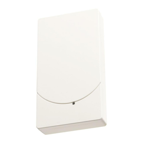
Page 16: External View
Setup The following diagram shows possible ways of integrating the radio gateway into the fire detection system on a FDnet/C-NET detector line. Figure 1: Radio gateway FDCW241 on detector line Radio cell 4 Radio gateway FDCW241 Radio fire detector FDOOT271... -
Page 17: Internal View
Structure and function Setup 3.1.3 Internal view Figure 3: Internal view of radio gateway FDCW241 1 Fastening tabs for strain relief 11 Cable entries 2 Socket strip, 2 poles H1 Red / green LED for detector line 3 Detector line socket strip... -
Page 18: Scope Of Delivery
Structure and function Function 3.1.4 Scope of delivery 1x radio gateway FDCW241 1x screw for cover 2x cable ties (2.4 x 102 mm) for cable strain relief Batteries are not included in the scope of delivery. A battery pack is always needed to commission and operate the radio gateway. -
Page 19: Behavior In Degraded Mode
External indicator, red and green (H1) Six indicators in the housing (H2, H3, H4, H5, H6, H7). You can see these if you open the housing cover. Figure 4: Radio gateway FDCW241 Red / green LED for detector line Yellow LED for maintenance mode... - Page 20 Structure and function Function Radio gateway status The table below describes the flashing behavior of the LEDs H1...H7 for gateway FDCW241. Indication Meaning Graphic H1, H2, H3, When a power supply is present, the radio gateway H4, H5, H6, operates without any problems.
-
Page 21: Power Supply
Structure and function Power supply Indication Meaning Graphic flashes 'Battery low' yellow The battery pack needs to be replaced. every seconds flashes 'Battery empty' yellow The battery pack is missing or not connected. twice every second flashes The connection to software tool FXS2061 has been green established. -
Page 22: Accessories
Batteries with battery cable Connector system with protection against polarity reversal Inscription field for commissioning date Compatible with: – Radio gateway FDCW241 – Radio manual call point FDM273 – Radio manual call point FDM275 – Radio manual call point FDM275(F) –... -
Page 23: Housing Base Fdch271
Interface converter for USB on MC link Compatible with: – Floor repeater terminal FT2010 – Floor repeater display FT2011 – Radio gateway FDCW221 and FDCW241 – Detector exchanger and tester FDUD292 – Intelligent detector tester FDUD293 – Line tester FDUL221 –... -
Page 24: Planning
Planning Compatibility FDnet/C-NET 4 Planning The radio connection means that there is no need to wire the radio devices, such as the radio fire detector, radio manual call point, etc., in the usual way. Together with the radio gateway, the radio devices form a radio cell. The control panel treats this radio cell as a loop or a stub. - Page 25 FDM275(F) You will find detailed information in the 'List of compatibility'. Limitations Maximum 16 FDCW241 radio gateways per line Reduced if length of line is over 2,200 m as per Sinteso Quantities tool (A6V10094878) or Cerberus PRO Quantities tool (A6V10211118)
-
Page 26: Mounting / Installation
Mounting / Installation Mounting 5 Mounting / Installation 5.1 Mounting Figure 5: Installing the radio gateway 1 Housing cover 2 Screw 3 Lock 4 Strain relief fastenings 5 Cable entries You have the radio gateway, battery pack, fixing screws, and cable tie to hand. You have the device location plan to hand. - Page 27 Mounting / Installation Mounting 6. Mount the back box, without the battery pack, on a flat surface using two screws (Ø max. 4.3 mm) at the mounting points (see 'Master gauge for recesses [ 59]' chapter). One screw at the mounting point is sufficient for fixing in housing FDCH221.
-
Page 28: Mounting In Housing Fdch221
Mounting / Installation Mounting in housing FDCH221 5.2 Mounting in housing FDCH221 The radio gateway can be installed in a separate housing FDCH221. The housing protects the radio gateway from dirt and dust. Ø max. 4.8 mm Figure 6: Installing housing FDCH221 1 Cable entry 4 Screws for securing the housing 2 Cables... -
Page 29: Connecting The Radio Gateway
FDCW241 FC72x SWING FC20xx FDCW241 FC72x Figure 7: Connecting the radio cell to the detector line 1 1 1 1 Figure 8: Connections on radio gateway FDCW241 detector line terminal strip 29 | 62 A6V10227639_k_en_-- Building Technologies Fire Safety 2016-11-28... - Page 30 Mounting / Installation Connecting the radio gateway The radio gateway 'FDCW241' automatically assigns the additional, virtual address 'FDCL221v' as a line separator. When you assign the connections, you determine the order in which the devices are read in at the control panel.
- Page 31 Mounting / Installation Connecting the radio gateway Radio cell as sub-stub on loop Figure 11: Sub-stub on loop connection Wiring connections NOTICE Failure of the electrical connection Damage to the screw terminals or contact problems may lead to faults in the electrical connection.
-
Page 32: Commissioning
Commissioning Basic rules for commissioning 6 Commissioning The procedure for commissioning via the control panel is no different to the one used for commissioning wired devices. The relevant fire detection system documents also apply to the SWING radio fire detection system. There are two operating conditions for radio cells. - Page 33 Commissioning Basic rules for commissioning Sequence for commissioning radio devices Working outwards from the radio gateway, commission the individual radio devices one after the other. The graphic below serves as an example of the correct sequence for commissioning radio devices. Figure 12: Example: Correct sequence for commissioning radio devices Radio gateway Radio device...
-
Page 34: Commissioning The Radio Cell
Start with the radio gateway. Activate the radio gateway, starting with the other radio devices. Figure 13: Radio gateway FDCW241 Yellow LED for maintenance S1 Button for maintenance mode mode... - Page 35 – Use line tester FDUL221. Make sure that the radio gateway is displayed with two addresses, as FDCL221v and as FDCW241. The radio cell is complete and the radio devices are logged on. 11. To switch the radio cell to normal operation, press and hold button (S1) for at least 2 seconds.
- Page 36 Commissioning Commissioning the radio cell 13. Connect the radio gateway and the detector line. – Switch the detector line off. – Insert the 'detector line socket strip'. The radio gateway is now connected to the detector line. 14. Close the radio gateway housing. 15.
-
Page 37: Maintenance / Troubleshooting
For control panels FC20xx: Document 009052 For control panels FC72x: Document A6V10210416 7.1 Establishing factory settings All settings are deleted and reset to the factory settings. Figure 14: Radio gateway FDCW241 Battery connector Reset button Yellow LED for reset 37 | 62... - Page 38 Maintenance / troubleshooting Establishing factory settings Proceed as follows to restore the radio gateway to the factory settings: The radio gateway must not be connected to the detector line. 1. Release the battery connector (1) to interrupt the power supply. 2.
-
Page 39: Putting The Radio Cell Into Maintenance Mode
Maintenance / troubleshooting Putting the radio cell into maintenance mode 7.2 Putting the radio cell into maintenance mode Figure 15: Radio gateway FDCW241 Yellow LED for maintenance mode Button for maintenance mode The housing for the radio gateway is open. -
Page 40: Putting The Radio Cell Into Normal Operation
Maintenance / troubleshooting Putting the radio cell into normal operation 7.3 Putting the radio cell into normal operation Figure 16: Radio gateway FDCW241 Yellow LED for maintenance mode Button for maintenance mode The housing for the radio gateway is open. -
Page 41: Adding Or Removing Radio Devices
Wait until one radio device has been successfully logged on before attempting to add the next radio device. The internal alarm indicator for the radio device is off. Figure 17: Radio gateway FDCW241 S1 Button for maintenance mode Yellow LED for maintenance... - Page 42 Maintenance / troubleshooting Adding or removing radio devices You have the new radio device and its battery pack to hand. You have a device location plan showing the locations of the radio devices in the radio cell. It is possible to access the station. 1.
-
Page 43: Removing Radio Devices Temporarily
Maintenance / troubleshooting Adding or removing radio devices 11. Close the radio gateway housing. 12. Switch the detector line on at the station and read in the new radio device in accordance with the documents for the fire control panel. Note the information in chapter 'Changing and expanding the FDnet/C-NET detector line' in the fire detection system documentation. -
Page 44: Removing Radio Devices Permanently
When radio devices are removed permanently, the radio cell changes. The SWING planning specifications must be adhered to. If you are removing multiple radio devices, you must finish removing one before you start removing the next one. Figure 18: Radio gateway FDCW241 Yellow LED for S1 Button for maintenance mode... - Page 45 Maintenance / troubleshooting Adding or removing radio devices 5. Remove the radio device from the base or housing. The internal alarm indicator flashes briefly at 2-second intervals. 6. Remove the base or housing. 7. Remove the battery pack from the radio device. 8.
-
Page 46: Replacing A Radio Device With Another Of The Same Type
If you want to replace multiple radio devices, you must finish replacing one device before you start replacing the next one. This will ensure that the site configuration does not change. Figure 19: Radio gateway FDCW241 Yellow LED for maintenance S1 Button for maintenance mode... - Page 47 Maintenance / troubleshooting Adding or removing radio devices 4. Remove the old radio device from the base or housing. The internal alarm indicator flashes briefly at 2-second intervals. 5. Remove the battery pack from the radio device. 6. Store, transport, and dispose of the battery pack in accordance with local regulations and laws.
-
Page 48: Connecting The Radio Cell To The Detector Line
Maintenance / troubleshooting Adding or removing radio devices 7.4.5 Connecting the radio cell to the detector line The detector line is switched off. The detector line terminal strip is connected according to chapter: Connecting the radio gateway [ 29]. All radio devices are logged on to the radio gateway. The radio gateway is set to normal operation. -
Page 49: Replacing The Radio Gateway And Transferring Data
2. Switch the detector line off. 3. Remove the cable connection to the detector line on the radio gateway. 4. Select the relevant radio gateway in the task card 'Network'. 5. Select the 'Update' command from the 'Exchange FDCW241' menu bar. 49 | 62 A6V10227639_k_en_--... - Page 50 Maintenance / troubleshooting Replacing the radio gateway and transferring data 6. Enter your password. The initial password is '1234'. 7. Follow the instructions exactly as they are shown in the window. 8. If you have carried out all the steps, then confirm this with 'OK'. The data is loaded from the old gateway.
-
Page 51: Firmware Update
Maintenance / troubleshooting Firmware update 7.6 Firmware update The firmware update is carried out using the software 'FXS2061 SWING Tool'. You will find a detailed description on how to perform the firmware update in document A6V10227643. We recommend inserting a new battery into the radio gateway before the firmware update. -
Page 52: Replacing The Batter Pack On The Radio Gateway
Maintenance / troubleshooting Replacing the batter pack on the radio gateway 7.8 Replacing the batter pack on the radio gateway Indications that the battery pack needs to be replaced: The control panel signals a battery fault for the radio gateway. LED (H1) flashes and LED (H5) flashes at 2-second intervals. -
Page 53: Messages And Consequences
Maintenance / troubleshooting Messages and consequences 9. Connect the battery connector (3). 10. Close the housing cover. The battery pack has now been replaced. The radio gateway is ready for operation immediately. There will be a delay before the fault message is cleared from the control panel. 7.9 Messages and consequences The following table shows all messages that can be displayed on the fire control panel and their meanings:... -
Page 54: Specifications
Specifications Technical data 8 Specifications Unless otherwise mentioned, the following data applies: Temperature = 25 °C Air pressure = 1000 hPa (750 Torr) You will find information on approvals on the data sheet for the device. 8.1 Technical data You will find information on approvals, CE marking, and the relevant EU directives for this device (these devices) in the following document(s);... - Page 55 Specifications Technical data Radio Number of radio devices per radio Max. 30 gateway as loop Max. 30 Number of radio devices per radio gateway as stub Sending/receiving aerials Dual band aerial Radio transmission: Frequency range 433.05…434.79 MHz in band 44b and 45b ¹...
- Page 56 Specifications Technical data Top band Bottom band Channel Frequency [MHz] Channel Frequency [MHz] 868.325 433.425 868.375 433.475 868.425 433.525 868.475 433.575 868.525 433.625 868.575 433.675 868.675 433.725 868.775 433.775 868.825 433.825 868.875 433.875 868.925 433.925 868.975 433.975 869.025 434.025 869.075 434.075 869.125 434.125...
- Page 57 Specifications Technical data Connections Detector line: Design Screw terminals on plug Cable cross section 0.2…1.5 mm² MC link: Design 3.5 mm jack socket Ambient conditions Operating temperature -10…+55 °C Storage temperature -30…+75 °C Air humidity 95 % rel. Protection category (IEC 60529): IP40 In housing FDCH221: IP65...
-
Page 58: Dimensions
Specifications Dimensions 8.2 Dimensions Radio gateway FDCW241 58 | 62 Building Technologies A6V10227639_k_en_-- Fire Safety 2016-11-28... -
Page 59: Master Gauge For Recesses
Specifications Master gauge for recesses 8.3 Master gauge for recesses 44.5 44.5 39.5 39.5 8.4 Environmental compatibility and disposal This equipment is manufactured using materials and procedures which comply with current environmental protection standards as best as possible. More specifically, the following measures have been undertaken: Use of reusable materials Use of halogen-free plastics... -
Page 60: Glossary
Glossary Glossary Radio cell Unit comprising all radio devices connected to the radio gateway Radio device Any device that the radio gateway monitors Radio network Within a radio cell, bidirectional radio connections are established between the radio devices. Together with the radio gateway connections, these create a radio network. -
Page 61: Index
Degraded mode operation Power supply ..........21 Collective behavior.......... 19 Fire control panel failure ........19 Radio gateway FDCW241 Diagnosis levels Replacing the radio gateway FDCW241 ..49 Overview ............18 Recycling ............59 Disposal ............59 Download center URL ..............7 Source language .......... - Page 62 Issued by © Siemens Switzerland Ltd, 2011 Siemens Switzerland Ltd Technical specifications and availability subject to change without notice. Building Technologies Division International Headquarters Gubelstrasse 22 CH-6301 Zug +41 41-724 24 24 www.siemens.com/buildingtechnologies Document ID: A6V10227639_k_en_-- Manual FD20/FD720 Edition: 2016-11-28...