
Related Manuals for Siemens NK8237 MP4.40


Summary of Contents for Siemens NK8237 MP4.40
- Page 1 NK8237 MP4.40 Modbus Gateway for Sinteso™ and Cerberus® PRO Fire Detection Systems Installation Function & Configuration Commissioning Safety Regulations Building Technologies Fire Safety & Security Products...
- Page 2 Data and design subject to change without notice. / Supply subject to availability. © 2011 Copyright by Siemens Switzerland Ltd We reserve all rights in this document and in the subject thereof. By acceptance of the document the recipient acknowledges these rights and undertakes not to publish the document nor the subject thereof in full or in part, nor to make them available to any third party without our prior express written authorization, nor to use it for any purpose other than for which it was delivered to him.
-
Page 3: Table Of Contents
About this document....................5 Safety regulations ...................7 Country-specific standards ...............7 Assembly and installation .................7 Commissioning and testing...............7 Disposal and recycling ................8 Modifications to the system design and the products .......8 Data Privacy and Protection ..............8 Introduction .....................9 NK8237 system overview .................9 Connectivity Examples................9 What has been changed in MP4.40............10 2.3.1... - Page 4 Configuration checklist ................30 Configuring IP settings via NW8202 ............32 Creating a new NK8237 Composer project ..........34 Creating the Modbus system ..............36 7.4.1 Modbus system creation procedure .........36 Creating the NK8237 gateway ..............37 7.5.1 NK8237 creation procedure............37 7.5.2 TCP/IP Modbus configuration procedure .........37 7.5.3 Serial Modbus configuration procedure........38 Configuring the fire network ..............40...
-
Page 5: About This Document
Training program information including the Siemens intranet link A complete list of all available DMS8000 documents Instructions for how to obtain a document via the Siemens intranet using the Siemens Asset Portal A map of relevant documents for each target audience group ... - Page 6 Safety regulations 3. In the resulting area on the right, select the document type (e.g. Contacts, Data Sheet, etc). For more information such as Siemens news and announcements, visit the STEP Web portal at: https://workspace.sbt.siemens.com/content/00001123/default.aspx Operational and safety regulations Before beginning work on the system you must have read and understood the Safety regulations section in this manual.
-
Page 7: Safety Regulations
Country-specific standards Siemens Building Technologies products are developed and produced in compli- ance with the relevant international and European safety standards. This document provides warnings and recommendations specific to NK8000 products. Any addi-... -
Page 8: Disposal And Recycling
Modifications to the system design and the products Modifications to a system or to individual products may cause faults or malfunc- tioning. Please request written approval from Siemens Building Technologies and from any relevant authorities concerning intended system modifications and system exten- sions. -
Page 9: Introduction
Introduction Introduction This section provides a general description of the NK8237 gateway. NK8237 system overview The NK8237 acts as gateway between Sinteso FS20/Cerberus PRO FS720 fire detection systems and Modbus head-end/automation systems connected via LAN or over a serial line. It provides for bi-directional Modbus RTU and TCP/IP connec- tivity for FS20/FS720 BACnet/IP fire detection systems. -
Page 10: What Has Been Changed In Mp4.40
Introduction What has been changed in MP4.40 Here is the list of modifications included in this version for new functions and im- provements. Section, Page Modifications New STEP portal 4, p.12 New mainboard NKM8001-A2 Fig. 5, p.14 6.1.1, p.23 New installation kit 6.1.3, p.25 New MP4.40 software setup 7.8, p.49... -
Page 11: System Limits
System limits System limits The following describes the system limits for the NK8237 units. Fire control units The following control units are supported: FC2020 FC2030 FC2040 FC2060 FT2040 FC722 FC724 FC726 FT744 Fire system topologies and max.connectivity ... -
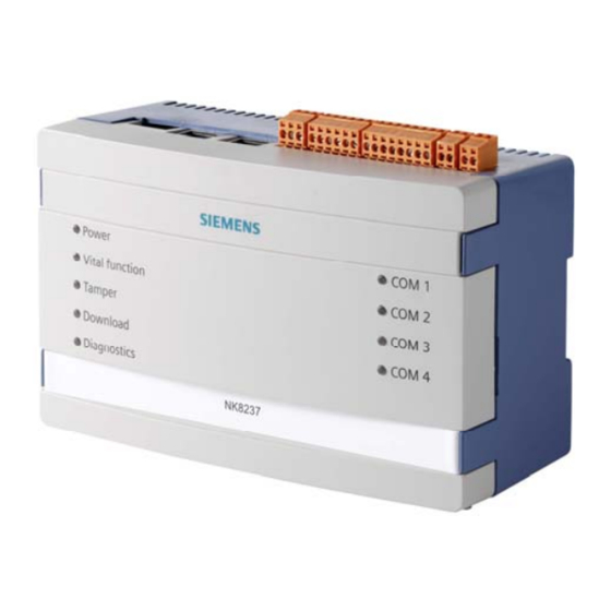
Page 12: Structure And Functions
Structure and functions Structure and functions The NK8237 is composed of an electronic board installed in a compact and robust plastic box. Note that NK8237 units with build state up to 01 are equipped with the NKM8001- A1 mainboard and NK8237 units with build state 10 or higher are equipped with the NKM8001-A2 mainboard. -
Page 13: Internal Dip Switches
Structure and functions The four LED's on the right side are, from top to bottom: Front panel LED (right Functions Com1 Status Com1 Com2 Red: Status Com2 Green: Com3 (not used) Status Com3 Com4 (not used) Status Com4 Tab.2.LED functions on the front panel, right side 4.1.2 Internal DIP switches The internal DIP switches (S101) enable a download session via FTP using a de-... -
Page 14: Serial Interfaces
Structure and functions S1: Reset button S2: Tamper switch S101: DIP-Switches X102 X103 X104 X101 X105 X111 Fig. 5 NK823x internal DIP switch and jumpers (NKM8001-A2 mainboard) 4.1.4 Serial interfaces The NK8237 is equipped with two serial lines available on the NK823x main board. The serial port can be configured as an RS232 interface using connector COM1 and COM2, or as an RS485 interface using connectors X104 and X105. -
Page 15: I 2 C Interface: Df8090 Power Supply Supervision
Structure and functions X102 onboard inputs Signal Circuit 1 Circuit 2 (internal power supply) (external power supply) Input 1 (Mains failure) Input 2 (Battery fault) Input 3 (Power supply fault) Common + Val - Val 4.1.6 C interface: DF8090 power supply supervision The I C interface (X11) allows for a direct support of: ... -
Page 16: Ethernet Interfaces
Structure and functions 4.1.7 Ethernet interfaces The NK823x main board is equipped with two Ethernet interfaces. The two RJ-45 connectors also include 2 LEDs (yellow and green) reporting the LAN status as fol- lows: Yellow LED: if on, a 100 Mbps link is active. ... -
Page 17: Hardware Installation
Hardware Installation Hardware Installation There are various possible NK8237 installation scenarios. Namely: 1. Installation of NK8237 in existing cabinets a. DIN-rail mounting (typical) in plastic housing. b. Mounting of the NK8237 board in the control unit housing using card holders (NKA8011-A1 required). 2. - Page 18 Hardware Installation 27Ah 12V Vin = Voltage In Vout = Voltage Out Batt = Battery Power supply connection Note the dual power supply input for redundant solutions Fig. 10 NK8237 power supply Caution! There is a risk of explosion if the battery is replaced with an incorrect battery type.
- Page 19 Hardware Installation X101: Onboard I/O (output relay) Assignment Common NO output NC output X102: Onboard I/O (inputs) Assignment Input 1 (Mains failure) Input 2 (Battery fault) Input 3 (Power supply fault) Common + Val - Val COM 1, COM 2: RS232 connectors RS232 lines are connected to 9pin D-Sub connectors, female type Assignment COM 1-2...
-
Page 20: Ne8000 Cabinets
Hardware Installation NE8000 cabinets 5.2.1 NE8000 hardware requirements Environmental requirements The cabinets for NK8237 should always be installed in a clean and safe environ- ment, away from dust, high temperature and humidity, vibrations and impacts. Conditions and power supply should match the specific requirements given in the Technical data section of the specific NK8000 datasheet. - Page 21 Hardware Installation Careful attention should be paid to the correct connections of Vac power lines. Input VAC 1.5 mm wires Fig. 13 VAC power connection Wires pass through 20mm (cut-out) holes* at the top of the cabinet (see Fig. 14), and continue behind the cabinet to pass through the rear-side cavity to the en- trance hole (see Fig.
- Page 22 Hardware Installation Fig. 15 Wiring (1) – Front view of cabinet (arrow indicates cut-out holes) Fig. 16 Wiring (2) – Entrance hole indicated by arrow Building Technologies 048_DMS_NK8237_ICC_MP4.40_A6V10316241_a_en.doc Fire Safety & Security Products 06.2011...
-
Page 23: Software Installation
Software Installation Software Installation NK8237 software installation includes the following: Composer and basic tools for system configuration, included in one of the DMS8000 product setup Refer to the MM8000 Installation, Configuration & Commissioning guide (document no. A6V10062413) NK8237 add-on, as described in 6.1 below ... -
Page 24: Installation Checklist
Software Installation 6.1.2 Installation checklist ITEMS NEEDED FOR THE INSTALLATION The DMS8000 Setup CD The add-on installation kit The DMS8000 Service key (dongle) The Service key license PAK code (or the REG file that contains it) INSTALLATION CHECKLIST ... -
Page 25: Composer Installation
Software Installation 6.1.3 Composer Installation Composer tool and its prerequisites can be installed using the standard DMS8000 6.1.3.1 Installing Composer software Composer tool can be installed using the standard DMS8000 CD by selecting the Composer and Subsystem Tool option in the Installation Wizard (see Fig. 18 and Fig. -
Page 26: Nk8237 Tools Installation
Software Installation For more information about how to install DMS8000 Composer and configure the license, refer to the MM8000 ICC guide (Installation, Configuration and Commissioning, document no. A6V10062413) and to the DMS8000 Network, Fire and Intrusion Connectivity Guide (document no.A6V10062425). 6.1.4 NK8237 tools installation A specific application, the Add-on manager, is provided by DMS8000 Composer... - Page 27 Software Installation Fig. 22 Installing the NK8237 add-on tools 3. If your installation includes a customized MM8000 internal account, deselect the checkbox Use default MM8000 User account and specify the customized username and password. If you do not know, leave the checkbox selected and proceed to the next step. 4.
-
Page 28: Nw8202 Ip Configuration Download Tool
Software Installation NW8202 IP configuration download tool The NW8202 is used to download the IP configuration data to the target NK82xx units. The NW8202 Tool allows a unique IP configuration to be assigned to the NK82xx(s). NW8202 should be installed on the PC used to send the IP configuration to the NK82xxs prior to shipment, or remotely after shipment (usually the Technician’s PC). -
Page 29: Nw8204 Maintenance And Diagnostic Tool
Software Installation NW8204 Maintenance and diagnostic tool The NW8204 is a powerful maintenance and diagnostic tool, which provides func- tionalities for (but not limited to) the following: Downloading firmware Setting IP addresses Loading default configurations Using available diagnostic files. Note 1: Part of the NW8204 tool is available in Composer (limited functionality). -
Page 30: Configuration
Configuration Configuration The following picture gives an overview about the configuration workflow. Engineering Sinteso Works Composer 3rd party configuration tool tools SiB-X BACnet/IP Ethernet Automation level ETH1 BACnet server BACnet client Modbus Slave Modbus Master Modbus RTU (RS-232) FC2020 Modbus GW Modbus device Field level Engineering data export... - Page 31 Configuration Items needed for configuration If used, the serial Modbus communication parameters should be defined. Configuration workflow If necessary, configure the NK8237 IP address(es) via NW8202 p. 32 In Composer, create the NK8237 project p. 34 Creating the Modbus system p.
-
Page 32: Configuring Ip Settings Via Nw8202
Configuration Configuring IP settings via NW8202 This configuration must be performed before the NK8237 can be configured at the client’s site. This procedure details how to send the IP configuration information; that is, the IP address, Subnet mask, and Default address to the NK8237 via the NW8202 Tool. - Page 33 Configuration Ethernet 1 Ethernet 2 Fig. 24 Connect Ethernet cables on NK8237 For direct connection between PC and NK8237, you can use either a crossed or straight-through Cat. 5 twisted pair patch cable. In fact, NK8237 supports auto- matic crossover. While the download is being performed, the FTP Diagnostic window is displayed with the current status of the download.
-
Page 34: Creating A New Nk8237 Composer Project
Configuration Creating a new NK8237 Composer project In the Composer environment, new NK8237 projects should be started from an empty template. Depending on the DMS8000 installation you have, there are two ways to do that. If your DMS8000 installation only includes the Composer tool (as documented in the installation section 6.1.3.1 at p. - Page 35 Configuration Tip: For a subsequent use, you may want to copy the Empty.bak file in a folder location more convenient to locate. 5. In the field Project name, enter a suitable name or select an existing project using the Browse button. 6.
-
Page 36: Creating The Modbus System
Configuration Creating the Modbus system This configuration task is performed in Composer on a project created for the NK8237 gateway starting from an empty template. The creation of the Modbus system is the first step of the NK8237 configuration. Failing to create the Modbus system at the very beginning prevents you from configuring the fire system and the rest of the project. -
Page 37: Creating The Nk8237 Gateway
Configuration Creating the NK8237 gateway This configuration task is performed in Composer on a project created for the NK8237 gateway starting from an empty template to which a Modbus system has been added. 7.5.1 NK8237 creation procedure Adding the folder for the NK8237 gateway 1. -
Page 38: Serial Modbus Configuration Procedure
Configuration Note: each route corresponds to a Route line command in the Windows Com- mand Prompt. The Ping button in the Tools tab can be used to check that the IP connectivity is properly established between the NK8237 and a destination IP address. - Page 39 Configuration The Modbus protocol node is created under the Protocols folder. By default, the new node is named “Modbus protocol #1”. 5. Select the new Modbus Protocol node. 6. Drag and drop the selection to one of the NK8237 COM ports. A link node is created under the COM port node.
-
Page 40: Configuring The Fire Network
Configuration Configuring the fire network This configuration task is performed in Composer on a project created for the NK8237 gateway starting from an empty template to which a Modbus system and an NK8237 unit have been added. The communication between FS20/FS720 and NK8237 is based on BACnet/IP. Communication parameters have to be configured on FS20/FS720 and NK8237 consistently. -
Page 41: Bacnet Configuration Procedure
Configuration Fig. 30 Selecting FC20/FC720 units (panels) to import 4. Select the units to import. Select All to import the structure of the entire fire system, or select the individ- ual units you want to import. After that, click OK. In a few moments, the FS20/FS720 structure is imported, all the units and the related nodes are represented in the Composer tree After the import procedure, selecting the Import tab results in a report being... - Page 42 Configuration Fig. 31 Example of FS20 System BACnet settings In the FS20/FS720 System settings, the BACnet Client Configuration section shows the valid client identifiers for the client stations. Note that one of them must correspond with the Device Identifier of the NK8237 (see p.44). Fig.
- Page 43 Configuration 2. In the toolbar on the left, select the BACnet Client Protocol icon (violet). The BACnet client protocol node is created under the Protocols folder. By default, the new node is named “BACnet Client Protocol”. 3. Select the new BACnet Client Protocol node. 4.
- Page 44 Configuration Linking the fire panels to the NK8237 All fire panels must be linked to the NK8237. Proceed as follows: 1. Select and expand the NK8237 Ethernet to display the BACnet Client Protocol. 2. Select the node of the first FC20xx/FC72x panel. 3.
-
Page 45: Customising The Modbus Interface
Configuration Customising the Modbus interface In the Modbus Master node, a number of configuration settings can be custom- ised related to general NK8237 gateway parameters as well as to the address of Modbus devices and data tables. The NK8237 handles a number of data tables to implement the Modbus commu- nication at application level. -
Page 46: Modbus Addresses
Configuration 3. In the Watchdog Timeout field, enter the maximum polling delay in seconds. Configuring the relay output (communication fault) 1. Select the NK8237 node and expand the subtree. 2. In the toolbar on the left, select the Onboard I/O icon A new Onboard I/O node appears. -
Page 47: Modbus Address Configuration Procedures
Configuration Modbus tables base address These parameters define the base address of the data tables that collect the fire system status in Modbus registers. For detailed information about these tables, refer to the NK8237 Interface Specifications guide (document no. A6V10316242). Fire object offset address These parameters define the offset address of the individual objects in the data ta- bles. - Page 48 Configuration 3. In the browsing window that appears, define the location and name of the file, and click Save. In a few moments, the CSV file is created. For detailed information about the CSV file structure, refer to the NK8237 In- terface Specifications guide (document no.
-
Page 49: Downloading The Nk8237
Configuration Downloading the NK8237 Configuration download The configuration download allows the Composer tool to transfer all the connec- tivity and Modbus settings into the NK8237 for runtime use. Once the NK8237 unit is connected over the IP network, this operation can be quickly performed from Composer using a right click command of the NK8237 node. -
Page 50: Nk83237 Firmware Download
Configuration 2. Select Node Commands Download Configuration File. The download procedure starts. Note: In the same menu, you can also create a backup copy of the NK8237 configuration INI file (Create INI file). After the download, the NK8237 unit stops and then reboots. The restarting phase is monitored by the Composer tool. -
Page 51: Nk8237 Connection Check
Configuration 6. Drag and drop the selection to the appropriate Ethernet node. A link node is created under the Ethernet node. 7. Select the BACnet Protocol link under the Ethernet node. 8. Drag and drop the selection to the NS8011 BACnet Driver node. A link node is created under the driver node. - Page 52 Configuration Note: In order to select multiple units, keep the CTRL key pressed while you make your selections. 3. Click the Download Configuration button. To ensure that download completed successfully, verify that the Cfg Downloaded checkbox contains X. The box is automatically unchecked after any subsequent modification to remind you that a further download is required.
-
Page 53: System Test
System Test System Test General checks on NK8237 The power supply, vital functions, and diagnostic state of NK8237 can be checked on the front panel. Refer to 4.1 at p.12. On the Modbus interface, the LifeCheck register provides a incremental counting as long as the NK8237 communication with the fire system and with the Modbus station works properly. -
Page 54: Maintenance And Diagnostics
Maintenance and diagnostics Maintenance and diagnostics Kernel update The NK8237 Kernel is the main component of the operating system, which acts as a bridge between the application and the hardware level. In certain conditions, it may be necessary to update the NK8237 Kernel, following specific instructions of the technical support. -
Page 55: Snmp Monitoring
Maintenance and diagnostics SNMP monitoring The NK823x units can support the SNMP protocol (Simple Network Management Protocol) to enable remote stations to monitor the units for conditions that may re- quire administrative attention. Using the SNMPv1 (RFC 1155-1157) on the UDP port 161, the NK823x provides two sets of internal information variables using the community IDs listed here be- low that enable the access to the MIB (Management Information Base) name- space. - Page 56 Maintenance and diagnostics Fig. 35 NW8204 window (installed GUI) 2. Insert the NK IP Address (NK82xx). Note: Inserting an incorrect IP address causes the following window to appear. If you receive this message, select OK and re-type the IP Address. If you want to enter the NK82xx default IP address 192.168.9.41, you can use the menu Set Default IP Address instead of typing it.
- Page 57 Maintenance and diagnostics Fig. 37 NW8204 window with open connection (installed GUI) Select do display user login window. See Information box previous page for a description of user types. Displays the version of the NW8204 tool. Browse for a local copy of DIAGNO.LOG or EEPROM.LOG to analyse/troubleshoot a remote NK82xx (admin user only).
-
Page 58: File Commands
Maintenance and diagnostics 9.3.2 File commands These commands are meant for remote technical maintenance and diagnostic of the NK82xx units. The commands apply to the file selection active in the list on the left hand side of the screen. Download file Transfer the selected file from the NK82xx. -
Page 59: Uploading Diagnostic Files
Maintenance and diagnostics 9.3.3 Uploading diagnostic files Diagnostic file purposes The purpose of these files is to record messages of what has taken place with the NK82xx to make it easier to determine if something is wrong, or if something im- portant has taken place. - Page 60 Maintenance and diagnostics EV_EEPROM_DLL_TIMEOUT DLL response time over threshold 3 EV_EEPROM_DLL_EVENT DLL diagnostic event EV_EEPROM_HW_MISMATCH PIC24 microcontroller init detected a hardware version different from version in EEProm EV_EEPROM_PIC24_FLASH_FAILURE PIC24 microcontroller init failed to write the micro- controller flash memory EV_EEPROM_PIC24_PROGRAMMED PIC24 microcontroller init wrote a new firmware into the microcontroller flash memory EV_EEPROM_PIC24_WRONG_HEX...
-
Page 61: Nw8204 Diagnostic Functions
Maintenance and diagnostics 9.3.4 NW8204 Diagnostic functions Reset NK Allows you to reset an NK82xx from a remote location. Note: This function is only available when logged in as user “admin”. Save EEProm on file Stores the content of the EEProm in the file EEProm.LOG on the NK82xx flash disk. - Page 62 Maintenance and diagnostics Read DLL Version Reads all subsystems configured. Displays a dialog box with a list of configured subsystems organised by name, number, and creation date. Read Kernel Version Reads the version of the Linux kernel installed on NK823x. Read NK Version Reads the version of the installed NK82xx firmware (NK82xx.EXE).
- Page 63 Maintenance and diagnostics Read HW version Reads the NK823x hardware version (NKM8001-A1, NKM8001-A2, …). Note that NK823x MP4.40 or later firmware is required. Read PIC24FW Ver Reads the PIC24 microcontroller firmware version. Note that NK823x MP4.40 or later firmware is required. Read WDT Status Reads the NK823x watchdog status (enabled or disabled).
-
Page 64: Menu "Send Default Configuration File
Maintenance and diagnostics 9.3.5 Menu “Send Default Configuration File” Sends a default configuration file containing only the new IP-configuration to the NK82xx. This function allows the download of a default configuration file with new IP pa- rameter settings to any reachable NK82xx, while NW8202 assumes that the NK82xx is set to default IP address before downloading the new configuration. -
Page 65: Correcting Communication Failures
Maintenance and diagnostics Correcting communication failures 9.4.1 Modbus communication problems If a communication fault occurs on the Modbus, there may be one or more causes. The problem may be in the NK8237 unit, or in the connections. Check the NK8237 Check power, vital function, and diagnostic state on the respective LED, which is located on the front panel. -
Page 66: Fire System Communication Problems
Maintenance and diagnostics ipconfig /all Shows comprehensive information about the local PC’s IP configuration (for example, the IP address) ping n.n.n.n Lets you check the communication with an IP network participant (“n.n.n.n” is the IP address to check) ping n.n.n.n –t Lets you continuously check the communication with an IP network participant (“n.n.n.n”... -
Page 67: Secure Operation Requirements
Compliance with local regulations must be addressed. This can concern paper listings as well as tapes and memory support. For further information on general security issues regarding Siemens products, please refer to the internal documentation and procedures on this subject. - Page 68 Siemens Switzerland Ltd Industry Sector Building Technologies Division International Headquarters Fire Safety & Security Products Gubelstrasse 22 © 2011 Copyright by CH-6301 Zug Siemens Switzerland Ltd Tel. +41 41 724 24 24 Data and design subject to change without notice.