
Related Manuals for Sony ICF-C253


Summary of Contents for Sony ICF-C253
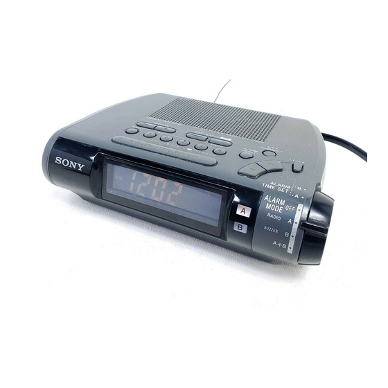
- Page 1 ICF-C253 SERVICE MANUAL Australian Model Ver 1.0 2000. 04 SPECIFICATIONS FM/AM PLL SYNTHESIZED CLOCK RADIO...
-
Page 2: Section 1 General
SECTION 1 This section is extracted from instruction manual. GENERAL SAFETY CHECK-OUT After correcting the original service problem, perform the following safety checks before releasing the set to the customer. Check the area of your repair for unsoldered or poorly-soldered Look for parts which, through functioning, show obvious signs connections. -
Page 3: Section 2 Disassembly
SECTION 2 DISASSEMBLY • The equipment can be removed using the following procedure. Key board Cabinet (upper) Main board Power board Note : Follow the disassembly procedure in the numerical order given. 2-1. CABINET (UPPER) × 14) 1 Five screws (M3 2 Cabinet (upper) 4 Speaker 3 Remove the two solderings. -
Page 4: Main Board
2-2. KEY BOARD 4 Key board 1 Two claws 2 Two claws 6 Chassis 5 Two claws 3 Remove the eight solderings. 7 Cabinet (lower) 2-3. MAIN BOARD 5 Remove the four solderings. × 8) 2 Two screws (BTP 2 3 Alarm dial board 6 LED board 1 Remove the... -
Page 5: Section 3 Electrical Adjustments
SECTION 3 ELECTRICAL ADJUSTMENTS 2-4. POWER BOARD [FM] • Adjusting Location: MAIN board (Component Side) Setting: BAND switch: FM T1 AM IF adjustment 4 Power cord 6 Transformer FM RF signal generator level meter FM TRACKING adjustment power L1 AM FREQUENCY COVERAGE 0.01 µ... -
Page 6: Led Board
ICF-C253 SECTION 4 DIAGRAMS 4-1. PRINTED WIRING BOARDS KEY BOARD MAIN BOARD TUNING S202 ANTENNA (SPEAKER) CN200 S210 S204 S200 S201 S203 S213 BAND CLOCK S212 A-RESET W151 S205 S209 S208 S207 S206 S214 TIME 1-676-850- (11) S211 SNOOZE S215... -
Page 7: Schematic Diagram
ICF-C253 4-2. SCHEMATIC DIAGRAM Note on Schematic Diagram: • All capacitors are in µF unless otherwise noted. pF: µµF 50 WV or less are not indicated except for electrolytics and tantalums. • All resistors are in Ω and W or less unless otherwise specified. -
Page 8: Section 5 Exploded Views
SECTION 5 EXPLODED VIEWS 4-3. IC PIN FUNCTION DESCRIPTION NOTE: • -XX, -X mean standardized parts, so they may • The mechanical parts with no reference number • IC100 LCD CONTROL (µPD17072GB-019-1A7) The components identified by mark 0 or have some differences from the original one. in the exploded views are not supplied. -
Page 9: Section 6 Electrical Parts List
SECTION 6 MAIN ELECTRICAL PARTS LIST NOTE: • Due to standardization, replacements in the • CAPACITORS: • SEMICONDUCTORS parts list may be different from the parts uF: µF In each case, u: µ, for example: specified in the diagrams or the components •... - Page 10 MAIN Ref. No. Part No. Description Remarks Ref. No. Part No. Description Remarks C119 1-163-021-91 CERAMIC CHIP 0.01uF JC15 1-216-296-91 SHORT C151 1-163-021-91 CERAMIC CHIP 0.01uF JC16 1-216-296-91 SHORT C152 1-163-021-91 CERAMIC CHIP 0.01uF JC17 1-216-296-91 SHORT C153 1-163-021-91 CERAMIC CHIP 0.01uF JC18 1-216-296-91 SHORT...
-
Page 11: Metal Chip
MAIN POWER Ref. No. Part No. Description Remarks Ref. No. Part No. Description Remarks 8-729-120-28 TRANSISTOR 2SC1623-L5L6 R120 1-216-238-91 RES-CHIP 1/8W 8-729-120-28 TRANSISTOR 2SC1623-L5L6 R151 1-216-198-91 RES-CHIP 1/8W Q100 8-729-216-22 TRANSISTOR 2SA1162-G R152 1-216-041-00 METAL CHIP 1/10W Q101 1-801-806-11 TRANSISTOR DTC144EKA-T146 R153 1-216-254-00 RES-CHIP... - Page 12 ICF-C253 Sony Corporation 2000D16053-1 Audio Entertainment Group 9-927-909-11 Printed in Japan ©2000.4 — 16 — Published by PE General Engineering Dept.