Sony ICF-C201 Service Manual
Fm/am clock radio
Hide thumbs
Also See for ICF-C201:
- Operating instructions (2 pages) ,
- Operating instructions (2 pages)
Table of Contents
Advertisement
SERVICE MANUAL
Ver.1.0 2006.03
Sony Corporation
9-887-137-01
Personal Audio Division
2006C02-1
Published by Sony Techno Create Corporation
© 2006.03
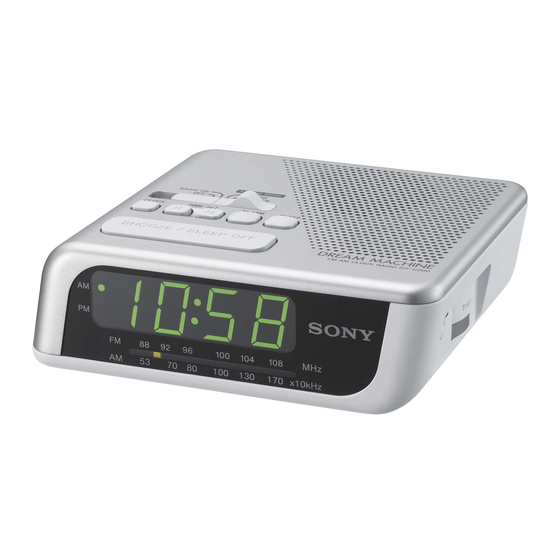
ICF-C201/C205
Photo: ICF-C205
SPECIFICATIONS
Time display:
ICF-C201
ICF-C205
Australian model : 12-hour system
Other models
Frequency range:
ICF-C201
FM: 87.5 - 108 MHz
ICF-C205
FM: 87.5 - 108 MHz
AM: 530 - 1 605 kHz
Speaker:
Approx. 5.7 cm (2
1
⁄
inches) dia., 8Ω
4
Power output:
150 mW (at 10 % harmonic distortion)
Power requirements:
ICF-C201
120 V AC, 60Hz
ICF-C205
230 V AC, 50Hz
For the power back-up function: 9 V DC, one 6F22 battery
Battery life:
Approx. 80 hours, using Sony 006P (6F22) battery
Dimensions:
Approx. 143 × 54.5 × 117.5 mm (w/h/d)
× 2
× 4
3
1
3
(5
⁄
⁄
⁄
inches) incl. projecting parts and controls
4
4
4
Mass:
ICF-C201
Approx. 340g (11.9 oz) not incl. battery
ICF-C205
Approx. 396g (14.0 oz) not incl. battery
Design and specifications are subject to change without notice.
Australian Model
12-hour system
: 24-hour system
FM CLOCK RADIO
FM/AM CLOCK RADIO
E Model
ICF-C201/C205
ICF-C205
ICF-C201
ICF-C205
Advertisement
Table of Contents

Related Manuals for Sony ICF-C201


Summary of Contents for Sony ICF-C201
- Page 1 120 V AC, 60Hz ICF-C205 230 V AC, 50Hz For the power back-up function: 9 V DC, one 6F22 battery Battery life: Approx. 80 hours, using Sony 006P (6F22) battery Dimensions: Approx. 143 × 54.5 × 117.5 mm (w/h/d) × 2 × 4 ⁄...
-
Page 2: Table Of Contents
COMPONENTS IDENTIFIED BY MARK 0 OR DOTTED LINE WITH MARK 0 ON THE SCHEMATIC DIAGRAMS AND IN THE PARTS LIST ARE CRITICAL TO SAFE OPERATION. REPLACE THESE COMPONENTS WITH SONY PARTS WHOSE PART NUMBERS APPEAR AS SHOWN IN THIS MANUAL OR IN SUPPLEMENTS PUBLISHED BY SONY. -
Page 3: General
ICF-C201/C205 SECTION 1 GENERAL This section is extracted from instruction manual. LOCATING THE CONTROLS ALARM MODE There is a tactile dot beside RADIO ON RADIO BUZZER VOLUME to show the direction to turn up the volume. ALARM SLEEP CLOCK TIME SET... -
Page 4: Setting Sleep Timer
ICF-C201/C205 Setting the Clock Setting the Alarm 1 Plug in the unit. To set the radio alarm, first tune in to a station and adjust the volume. The display will flash “AM 12:00”. 1 To set the hour for alarm, while holding down ALARM, press 2 To set the hour, while holding down CLOCK, press TIME TIME SET H. -
Page 5: Disassembly
ICF-C201/C205 SECTION 2 DISASSEMBLY • This set can be disassembled in the order shown below. Upper cabinet assy MAIN board Note: Follow the disassembly procedure in the numerical order given. 2-1. UPPER CABINT ASSY 4 two claws 6 upper cabinet assy... -
Page 6: Installation Power Cord And Pointer Installation
ICF-C201/C205 INSTALLATION POWER CORD AND POINTER INSTALLATION wind the power power cord cord clockwise once. lower cabinet (top view) 1 turn the knob (TUNE) fully counterclockwise. 2 turn the knob (VOL) fully counterclockwise. MAIN board (top view) 3 turn CV1 fully... -
Page 7: Electrical Adjustments
Adjust for a maximum reading on level meter. generator 86.5MHz 109.5MHz 0.01 µ F antenna terminal FM TRACKING ADJUSTMENT JW6 (ICF-C201) JW7 (ICF-C205) Adjust for a maximum reading on level meter. 22.5kHz frequency deviation by confirm 86.5MHz 400Hz signal. Output level : as low as possible 109.5MHz... - Page 8 ICF-C201/C205 Adjustment Location: MAIN board (Component side) L4 : AM Frequency Coverage Adjustment L1 : AM Tracking Adjustment (ICF-C205) L3 : FM Frequency Coverage Adjustment CT1-4 (ICF-C201) (ICF-C205) T1 : AM IF Adjustment CT1-4 CT4 : AM Frequency Coverage Adjustment...
-
Page 9: Diagrams
ICF-C201/C205 SECTION 4 DIAGRAMS 4-1. PRINTED WIRING BOARD LED DISPLAY MAIN BOARD (C205) (C201) (C205) 15 16 (C201) (C205) (C205) BAND C16 C15 C13 C12 POWER TRANSFORMER (C205) AC IN (C205:SP,TH) (C205) (C201) ALARM CLOCK SLEEP FERRITE-BAR ANTENNA (C205) (C201) -
Page 10: Schematic Diagram
ICF-C201/C205 4-2. SCHEMATIC DIAGRAM Note: • All capacitors are in µF unless otherwise noted. (p: pF) 50V or • Voltages are taken with a VOM (Input impedance 10 MΩ). less are not indicated except for electrolytics and tantalums. Voltage variations may be noted due to normal production toler- •... -
Page 11: Ic Block Diagrams
ICF-C201/C205 • IC Block Diagram IC1 CXA1019M AM IF DET AGC TUNING METER AF POWER AMP AM FE FM IF DISCRIMINATOR FM FE IC2 LM8560N 26 25 16 15 50/60Hz 50/60Hz 50/60Hz 50/60Hz 50/60Hz 50/60Hz OUTPUT CONTROL CONTROL GATE 1/25 OR 1/30 S.SAMPLE... -
Page 12: Exploded Views
ICF-C201/C205 SECTION 5 EXPLODED VIEWS NOTE: The components identified by mark 0 or • The mechanical parts with no reference number • -XX, -X mean standardized parts, so they may dotted line with mark 0 are critical for in the exploded views are not supplied. -
Page 13: Electrical Parts List
ICF-C201/C205 SECTION 6 MAIN ELECTRICAL PARTS LIST NOTE: • Due to standardization, replacements in the • COILS The components identified by mark 0 uH: µH parts list may be different from the parts or dotted line with mark 0 are critical specified in the diagrams or the components •... - Page 14 ICF-C201/C205 MAIN Ref. No. Part No. Description Remarks Ref. No. Part No. Description Remarks 8-719-063-79 DIODE 1N4002B MISCELLANEOUS 1-802-103-11 ELEMENT,LED INDICATOR (C201) ************** 1-802-103-21 ELEMENT,LED INDICATOR (AUS) 1-802-103-31 ELEMENT,LED INDICATOR (SP,TH) 1-769-339-82 CORD, POWER (C201) 8-719-062-51 DIODE 1PS226-115 1-777-921-13 CORD, POWER (C205:SP, TH) 1-831-261-11 CORD, POWER (C205:AUS) <...
- Page 15 ICF-C201/C205 MEMO...
- Page 16 ICF-C201/C205 REVISION HISTORY Clicking the version allows you to jump to the revised page. Also, clicking the version at the upper right on the revised page allows you to jump to the next revised page. Ver. Date Description of Revision...