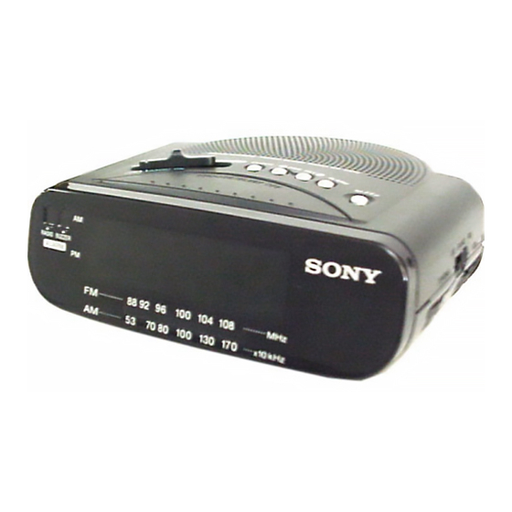
Sony ICF-C212 Service Manual
Fm/am clock radio
Hide thumbs
Also See for ICF-C212:
- Operating instructions (5 pages) ,
- Specifications (2 pages) ,
- Operating instructions (2 pages)
Table of Contents
Advertisement
SERVICE MANUAL
Ver 1.0 2003.03
Time display:
North and South America, Australia:12-hour system
Other countries/regions: 24-hour system
Frequency range:
FM
87,5 - 108 MHz
AM
530 - 1 710 kHz
Speaker:
Approx. 6.6 cm (2
5
⁄
inches) dia., 8Ω
8
Power output:
150 mW (at 10 % harmonic distortion)
Power requirements:
230 V AC, 50 Hz
For the power back-up function: 9 V DC, one 6F22 battery
Battery life:
Approx. 80 hours, using Sony 006P (6F22) battery
Sony Corporation
9-877-143-01
Personal Audio Company
2003C0200-1
© 2003.03
Published by Sony Engineering Corporation
ICF-C212
SPECIFICATIONS
Dimensions:
Approx. 165 x 64.5 x 146 mm
(w/h/d) (6
projecting parts and controls
Mass:
Approx. 522 g (1 lb 3 oz.) not incl. battery
Design and specifications are subject to change without notice.
E Model
Australian Model
1
5
3
⁄
x 2
⁄
x 5
⁄
inches) incl.
2
8
4
FM/AM CLOCK RADIO
Advertisement
Table of Contents

Related Manuals for Sony ICF-C212


Summary of Contents for Sony ICF-C212
- Page 1 150 mW (at 10 % harmonic distortion) Power requirements: 230 V AC, 50 Hz For the power back-up function: 9 V DC, one 6F22 battery Battery life: Approx. 80 hours, using Sony 006P (6F22) battery FM/AM CLOCK RADIO Sony Corporation 9-877-143-01 Personal Audio Company 2003C0200-1 ©...
-
Page 2: Table Of Contents
COMPONENTS IDENTIFIED BY MARK 0 OR DOTTED LINE WITH MARK 0 ON THE SCHEMATIC DIAGRAMS AND IN THE PARTS LIST ARE CRITICAL TO SAFE OPERATION. REPLACE THESE COMPONENTS WITH SONY PARTS WHOSE PART NUMBERS APPEAR AS SHOWN IN THIS MANUAL OR IN SUPPLEMENTS PUBLISHED BY SONY. -
Page 3: General
ICF-C212 SECTION 1 GENERAL This section is extracted from instruction manual. LOCATION AND FUNCTION OF CONTROLS Function selector AC power cord FM wire antenna ALARM RADIOB UZZE R There is a tactile dot beside VOL to show the direction to turn up the volume. -
Page 4: Setting The Alarm
ICF-C212 Setting the Alarm Setting the Clock To set the radio alarm, first tune in to a station and adjust the volume. 1 Plug in the unit. 1 To set the hour for alarm, while holding down ALARM, press TIME The display will flash “AM 12:00”... -
Page 5: Disassembly
ICF-C212 SECTION 2 DISASSEMBLY The equipment can be removed using the following procedure. Cabinet (upper) Main board Note : Follow the disassembly procedure in the numerical order given. 2-1. CABINET (UPPER) Cabinet (upper) 2 Claw 2 Claw 4 Claw Panel... -
Page 6: Installation Power Cord
ICF-C212 INSTALLATION POWER CORD Cabinet (lower) Power cord Wind the power cord to the boss twice POINTER INSTALLATION Main board 2 Turn RV1 fully in the arrow direction. 1 Turn the shaft of CV1 fully in the arrow direction. Marking... -
Page 7: Electrical Adjustments
ICF-C212 SECTION 3 ELECTRICAL ADJUSTMENTS • Repeat the procedures in each adjustment several times, and the TUNER SECTION frequency coverage and tracking adjustments should be finally done by the trimmer capacitors. AM/LW Section 0dB=1µV Procedure : AM IF ADJUSTMENT BAND : AM Adjust for a maximum reading on level meter. - Page 8 ICF-C212 Adjustment Location : Main board (Component side) T1 : AM IF Adjustment L3 : FM Frequency Coverage Adjustment L2 : FM Tracking Adjustment L1 : AM Tracking Adjustment CT3 : FM Frequency Coverage Adjustment CT2 : FM Tracking Adjustment...
-
Page 9: Diagrams
ICF-C212 SECTION 4 DIAGRAMS 4-1. PRINTED WIRING BOARDS DISPLAY [MAIN BOARD] RADIO RADIO BUZZER CV1-4 ALARM MODE 15 16 TUNING FERRITE-ROD ANTENNA POWER TRANSFORMER JW11 SLEEP CLOCK AC IN SP MODEL ALARM JW10 BAND TIME SET TIME SET BPF1 ANT1... -
Page 10: Schematic Diagram
ICF-C212 4-2. SCHEMATIC DIAGRAM Note: • Voltages are dc with respect to ground under • All capacitors are in µF unless otherwise noted. pF: µµF • Signal path. no-signal conditions. : FM 50 WV or less are not indicated except for electrolytics no mark : FM •... -
Page 11: Ic Block Diagrams
ICF-C212 IC Block Diagrams IC1 CXA1019S AM IF DET AGC TUNING METER AF POWER AMP AM FE FM IF DISCRIMINATOR FM FE IC2 LM8560N 26 25 16 15 50/60Hz 50/60Hz 50/60Hz 50/60Hz 50/60Hz 50/60Hz OUTPUT CONTROL CONTROL GATE 1/25 OR 1/30 S.SAMPLE... -
Page 12: Exploded View
ICF-C212 SECTION 5 EXPLODED VIEW NOTE : • -XX, -X mean standardized parts, so they • The mechanical parts with no reference The components identified by mark 0 may have some difference from the original number in the exploded views are not or dotted line with mark 0 are critical one. -
Page 13: Electrical Parts List
ICF-C212 SECTION 6 MAIN ELECTRICAL PARTS LIST NOTE : • Due to standardization, replacements in the • SEMICONDUCTORS The components identified by mark 0 parts list may be different from the parts In each case, u : µ , for example :... - Page 14 ICF-C212 MAIN Ref. No. Part No. Description Remark 1-216-849-11 METAL CHIP 220K 1/10W 1-216-845-11 METAL CHIP 100K 1/10W 1-247-791-91 CARBON 1/4W 1-216-833-11 METAL CHIP 1/10W 1-216-833-11 METAL CHIP 1/10W 1-216-803-11 METAL CHIP 1/10W < VARIABLE RESISTOR > 1-228-790-00 RES, VAR, CARBON 50K (VOLw) <...
- Page 15 ICF-C212 MEMO...
- Page 16 ICF-C212 REVISION HISTORY Clicking the version allows you to jump to the revised page. Also, clicking the version at the upper right on the revised page allows you to jump to the next revised page. Ver. Date Description of Revision...