Table of Contents
Advertisement
Quick Links
Advertisement
Table of Contents

Related Manuals for Zenoah BC2002


Summary of Contents for Zenoah BC2002
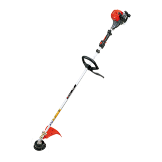
- Page 1 OWNER’S MANUAL BRUSHCUTTERS BC2002 TR2001 848J6093A0 (311) GB-1...
- Page 2 EXPLANATION OF SYMBOLS AND SAFETY WARNINGS WARNING!!! RISK OF DAMAGING HEARING IN NORMAL CONDITIONS OF USE, THIS MACHINE MAY INVOLVE A DAILY LEVEL OF PERSONAL EXPOSURE TO NOISE FOR THE OPERATOR EQUAL TO OR GREATER THAN 85 dB(A) MODEL SOUND LEVEL VIBRATION LEVEL ISO 7916 ISO 10884...
-
Page 3: Table Of Contents
SAFETY FIRST Instructions contained in warnings within this manual marked with a symbol concern critical points which must be taken into consideration to prevent possible serious bodily injury, and for this reason you are requested to read all such instructions carefully and follow them without fail. -
Page 4: Parts Location
H) ... 1795 x 230 x 303 / 1795 x 340 x 303 mm Dry weight ... 4.1 / 4.7 kg Engine Type ... Air-cooled 2-stroke gasoline Model ... Zenoah G20LS Displacement ... 21.7 cm Fuel ... Mixture (Gasoline 50 : Oil 1) Carburetor ... Diaphragm type Ignition system ... -
Page 5: Warning Labels On The Machine
3. Warning labels on the machine Read owner’s manual before operat- ing this machine. Wear head, eye and ear protection. Warning / Attention Keep all children, bystanders and helpers 15 meters away from the machine. 4. Symbols on the machine For safe operation and maintenance, symbols are carved in relief on the machine. -
Page 6: For Safe Operation
5. For safe operation 1. Read this manual carefully until you completely understand and follow all safety and operating instructions. 2. Keep this manual handy so that you may refer to it later when- ever any questions arise. Also note, if you have any questions which cannot be answered herein, contact the dealer from whom you purchased the prod-... - Page 7 If it continues to rotate even after the throttle has been moved fully back, turn off the engine and take the unit to your authorized KOMATSU ZENOAH servicing dealer for re- pair. USING THE PRODUCT IMPORTANT Cut only materials recommended by the manufacturer.
- Page 8 KOMATSU ZENOAH prod- ucts or products which have been certified by KOMATSU ZENOAH for use with the KOMATSU ZENOAH product. 4. In the event that any part must be replaced or any maintenance or...
-
Page 9: Set Up
6. Set up INSTALLING HANDLE • Install the handle to the shaft tube and clamp. INSTALLING DEBRIS GUARD • Attach the guard to the bracket on the main pipe and fix it with 2 screws. INSTALLING CUTTING HEAD 1. While locking the gear shaft, by inserting the supplied tool into the upper holder on the gearbox, loosen and remove the hexagon nut (left-handed). -
Page 10: Fuel
3 m (10 ft) away from the fueling point before starting the engine. • The Komatsu Zenoah engines are lubricated by oil specially formulated for air-cooled 2-cycle gasoline engine use. If Komatsu Zenoah oil is not available,... -
Page 11: Operation
8. Operation STARTING ENGINE WARNING The cutting head will start rotating upon the engine starts. 1. Feed fuel into the fuel tank and tighten the cap se- curely. 2. Rest the unit on a flat, firm place. Keep the cutting head off the ground and clear of surrounding objects, as it will start rotating upon starting of the engine. - Page 12 8. Operation ADJUSTING THROTTLE CABLE • The normal play is 1 or 2 mm when measured at the carburetor side end. Readjust with the cable adjuster as required. .04 in (1 ~ 2 mm) (1) Cable adjuster ADJUSTING IDLING SPEED (1) Idle adjusting screw 1.
-
Page 13: Maintenance
9. Maintenance System/components fuel leaks, fuel spillage fuel tank, air filter, fuel filter idle adjusting screw spark plug cylinder fins, intake air cooling vent muffler, spark arrester, cylinder exhaust port throttle lever, ignition switch cutting parts gear case screws/nuts/bolts debris guard WARNING •... - Page 14 Clean the spark plug and check that the plug gap is in the correct range. For a re- placement plug, use the correct type specified by KOMATSU ZENOAH. 0.6~0.7 mm • REPLACEMENT PLUG IS A NGK BPMR7A.
-
Page 15: Storage
9. Maintenance PROCEDURES TO BE PERFORMED AFTER EVERY 100 HOURS OF USE 1. Remove the muffler, insert a screwdriver into the vent, and wipe away any carbon buildup. Wipe away any carbon buildup on the muffler exhaust vent and cylin- der exhaust port at the same time. -
Page 16: Troubleshooting Guide
(exhaust port) → carbon is built-up air cleaner cylinder fin, fan cover When your unit seems to need further service, please consult with our KOMATSU ZENOAH Limited warranty Should any failure occur on the product under normal oper-...