Table of Contents
Advertisement
Quick Links
Advertisement
Table of Contents

Related Manuals for TYAN TS65-B8253


Summary of Contents for TYAN TS65-B8253
- Page 1 TS65-B8253 Service Engineer’s Manual http://www.tyan.com...
- Page 2 MITAC assumes no liability whatsoever, and ® disclaims any express or implied warranty, relating to sale and/or use of TYAN products including liability or warranties relating to fitness for a particular purpose or merchantability. MITAC retains the right to make changes to produce descriptions and/or specifications at any time, without notice.
- Page 3 This Class A digital apparatus complies with Canadian ICES-003. Cet appareil numérique de la Classe A est conforme à la norme NMB-003 du Canada. Notice for Europe (CE Mark) ● This product is in conformity with the Council Directive 2014/30/EU and 2014/35/EU. http://www.tyan.com...
- Page 4 Replace only with the same or equivalent type recommended by manufacturer. Dispose of used battery according to manufacturer instructions and in accordance with your local regulations. VCCI-A ● この装置は、クラスA機器です。この装置を住宅環境で使用すると電波妨害を引き 起こすことがあります。この場合には使用者が適切な対策を講ずるよう要求される VCCI-A ことがあります。 Safety: IEC/EN 62368-1 ● This equipment is compliant with CB/LVD of Safety: IEC/EN 62368-1. http://www.tyan.com...
- Page 5 This manual is intended for skilled person with hardware knowledge of computers. Components inside the compartments should be serviced only by a skilled person. This manual is aimed to provide you with instructions on installing your TYAN TS65-B8253. How this guide is organized...
- Page 6 Safety and Compliance Information Before installing and using TYAN TS65-B8253, take note of the following precautions: ·Read all instructions carefully. ·Do not place the unit on an unstable surface, cart, or stand. ·Do not block the slots and opening on the unit, which are provided for ventilation.
- Page 7 You must become familiar with the safety information in this guide before you install, operate, or service TYAN products. Symbols on Equipment Caution. This symbol indicates a potential hazard.
- Page 8 · Do not attempt to move a fully loaded rack. Remove equipment from the rack before moving it. · Do not attempt to move a rack on an incline that is greater than 10 degrees http://www.tyan.com...
- Page 9 This will reduce the risk of personal injury, fire, or damage to the equipment. The total rack load should not exceed 80 percent of the branch circuit rating. Consult the electrical authority having jurisdiction over your facility wiring and installation requirements. http://www.tyan.com...
- Page 10 · Dispose of used batteries according to the instructions of the manufacturer. Do not dispose of batteries with the general household waste. To forward them to recycling or proper disposal, use the public collection system or return them to TYAN, your authorized TYAN partner, or their agents. http://www.tyan.com...
- Page 11 Equipment Modifications · Do not make mechanical modifications to the system. TYAN is not responsible for the regulatory compliance of TYAN equipment that has been modified. Equipment Repairs and Servicing · The installation of internal options and routine maintenance and service of...
-
Page 12: Table Of Contents
Table of Contents Chapter 1: Overview............... 15 About the TYAN TS65-B8253 ..........15 Product Model ................ 15 Features .................. 16 Standard Parts List ..............23 1.4.1 Box Contents ..............23 1.4.2 Accessories ..............23 ... - Page 13 Appendix II: Cable Connection Tables ......... 87 Appendix III: Fan and Temp Sensors ........... 89 Appendix IV: PCI-E Slot Serial Number ........93 Appendix V: FRU Parts Table ............97 Appendix VI: Technical Support ........... 99 http://www.tyan.com...
- Page 14 http://www.tyan.com...
-
Page 15: Chapter 1: Overview
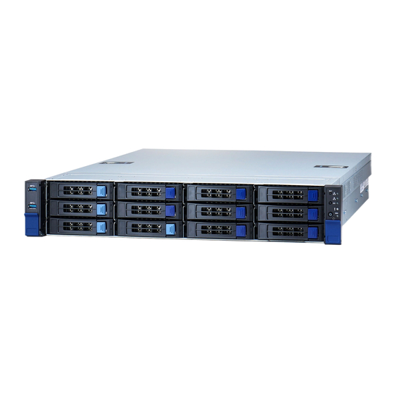
® SSD/HDD. The TS65-B8253 uses TYAN ’s latest chassis, featuring a robust structure and a solid mechanical enclosure. All of this provides TS65-B8253 the power and flexibility to meet the needs of nowadays server applications. Product Model The system board within the Tyan Barebone is defined by the following model: B8253T65V10E4HR ... -
Page 16: Features
External Drive Bay Interface (@ rear) The SAS/SATA HDD backplane is connected to onboard SATA connection by default. Please Notification contact Tyan technical support if a discrete SAS HBA/RAID adapter is required. System Cooling (3) 8cm fans Configuration Type CRPS... - Page 17 Memory voltage 1.2V (1) PCI-E Gen4 x32 slot, (3) PCI-E PCI-E Gen4 x16 slot, (1) PCI-E Gen4 x8 slot Pre-install TYAN Expansion Slots (1) M8253T65-R32-3F riser card for Riser Card (3) FH/HL PCI-E Gen4 x8 slot (right) (PCI-E Gen4) Physical Dimension FH/HL (Full-height, Half-length): 4.4"...
- Page 18 USB device/PXE via LAN/Storage, Feature Console Redirection, ACPI 6.1, ACPI sleeping states S0, S5, FAN speed control automatic Please refer to our AVL support Operating System OS supported list lists. FCC (SDoC) Class A CE (DoC) Class A Regulation CB/LVD Class A http://www.tyan.com...
- Page 19 External Drive Bay Interface (@ rear) The SAS/SATA HDD backplane is connected to onboard SATA connection by default. Please Notification contact Tyan technical support if a discrete SAS HBA/RAID adapter is required. System Cooling (3) 8cm fans Configuration Power Supply...
- Page 20 Memory voltage 1.2V (1) PCI-E Gen4 x32 slot, (3) PCI-E PCI-E Gen4 x16 slot, (1) PCI-E Gen4 x8 slot Pre-install TYAN Expansion Slots (1) M8253T65-R32-3F riser card for Riser Card (3) FH/HL PCI-E Gen4 x8 slot (right) (PCI-E Gen4) Physical Dimension FH/HL (Full-height, Half-length): 4.4"...
- Page 21 Server Management 2.0 virtual hub IPMI 2.0 compliant baseboard AST2500 IPMI management controller (BMC), Feature 10/100/1000 Mb/s MAC interface Brand / ROM size AMI, 32MB Hardware Monitor, SMBIOS BIOS Feature 3.0/PnP/Wake on LAN, Boot from USB device/PXE via LAN/Storage, http://www.tyan.com...
- Page 22 In/Non-operating 90%, non-condensing at 35° C Humidity RoHS RoHS 6/6 Compliant Barebone (1) TS65-B8253 Barebone Package Contains Manual (1) Quick Installation Guide NOTE: 1. The specifications are subject to change without prior notice. 2. Please visit our website for the latest specifications.
-
Page 23: Standard Parts List
Standard Parts List This section describes TS65-B8253 package contents and accessories. Open the box carefully and ensure that all components are present and undamaged. The product should arrive with packaged as illustrated below. 1.4.1 Box Contents If any items are missing or appear damaged, contact your retailer or browse to TYAN’s website for service: http://www.tyan.com... -
Page 24: About The Product
HDD LED (N/A, always OFF) 3.5” / 2.5” SSD/HDD/NVMe bays RESET Button NOTE: The Front Panel HDD LED is dedicated for M.2 HDD only. The S8253 mainboard does not support M.2. Therefore, The Front Panel HDD LED is always OFF. http://www.tyan.com... - Page 25 Status LED (Red) Drive present, no activity Green Solid On Drive present with activity Green Blinking Drive Fail Don’t care Red Solid On Drive identify Don’t care Red Blinking @ 1Hz Drive Rebuild Don’t care Red Blinking @ 4Hz http://www.tyan.com...
-
Page 26: System Rear View
ID LED will light blue if the system is identified. Users from remote sites can also activate the ID LED by entering a few commands in IPMI. For detailed software support, please visit http://www.tyan.com for the latest AST2500 user guide. - Page 27 (Link/Activity) (Speed) No Link Link Solid Green Solid Green 100 Mbps Active Blinking Green Solid Green Link Solid Green Solid Amber 1000 Mbps Active Blinking Green Solid Amber Link Solid Amber Solid Amber (10Gbps) Active Solid Amber Solid Amber http://www.tyan.com...
-
Page 28: System Top View
1.5.3 System Top View M1717T65-USB USB Board (pre-installed) M1718T65-FPB Front Panel Board (pre-installed) HDD Bays M1297T65-BP12E-12 HDD backplane Board (pre-installed) System fans M7100F48B-PDB Power Distribution Board Power Modules M1298T65-BP12E-2 HDD backplane Board (pre-installed) Riser Card Bracket (M8253T65-R32-3F pre-installed) http://www.tyan.com... -
Page 29: Chassis Dimension
1.5.4 Chassis Dimension http://www.tyan.com... -
Page 30: Board Image
1.5.5 Board Image S8253GM4NE-2T This picture is representative of the latest board revision available at the time of publishing. The board you receive may not look exactly like the above picture. http://www.tyan.com... -
Page 31: Block Diagram
1.5.6 Block Diagram S8253 Block Diagram NOTE: Please visit our TYAN web site for more MB details on S8253. http://www.tyan.com... - Page 32 NOTE http://www.tyan.com...
-
Page 33: Chapter 2: Setting Up
Caution! To avoid damaging the motherboard and associated components, use torque force within the range kgf/cm (6.09 lb/in) on each mounting screw for motherboard installation. Do not apply power to the board if it has been damaged. http://www.tyan.com... -
Page 34: Precautions
Components and electronic circuit boards can be damaged by discharges of static electricity. Working on a system that is connected to a power supply can be extremely dangerous. Follow the guidelines below to avoid damage to TS65-B8253 or injury to yourself. -
Page 35: Installing Motherboard Components
CPUs, memory modules and add on cards. 2.1.1 Removing the Chassis Cover Follow these instructions to remove TS65-B8253 chassis cover. 1. Loosen two screws on the top cover. 2. Push the latches simultaneously and slide the chassis cover backwards. 3. Lift the chassis cover up. -
Page 36: Removing The Riser Bracket And Air Duct
2.1.2 Removing the Riser Bracket and Air Duct 1. Use a screwdriver to loosen the thumb screw and then lift up the Riser Card Bracket and the air duct. http://www.tyan.com... -
Page 37: Replacing The Chassis Cover
2.1.3 Replacing the Chassis Cover Follow these instructions to replace TS65-B8253 chassis cover. 1. Place the chassis cover on top. 2. Push the latches simultaneously and slide the chassis cover forwards until it clicks. 3. Use a screw driver to fasten the screws on the top cover. -
Page 38: Installing The Cpu And Heatsink
2.1.4 Installing the CPU and Heatsink The TS65-B8253 supports dual AMD Socket SP3. The following instruction is a sample showing how to install a CPU on an AMD Socket SP3. Follow the steps below to install CPUs and CPU heat sinks. - Page 39 4. Align and install the carrier frame with package into the slot on the rail frame. 5. Using your thumbs and forefinger, remove the PnP cap by lifting it up vertically. Carefully close the rail frame with the installed package. Then push both edges of the rail frame firmly until it locks in place. http://www.tyan.com...
- Page 40 7. To secure the heatsink, use a T20 Security Torx to tighten four screws. Tighten four screws in a diagonal sequence to secure the heat sink. Repeat the same procedures described earlier to install the second processor and heatsink. http://www.tyan.com...
- Page 41 8. Take out the air duct. Remember to install the air duct after the second processor and heatsink are installed. http://www.tyan.com...
-
Page 42: Installing The Pci-E Card
2. Unscrew to remove the dummy bracket. 3. Insert the PCI-E card into the slot and screw it firmly to the riser card bracket. 4. Replace the riser card bracket into the chassis and use a screw driver to fasten the thumb screw. http://www.tyan.com... -
Page 43: Installing The Memory
2. Align the memory module with the slot. When inserted properly, the memory slot locking levers lock automatically onto the indentations at the ends of the module. Follow the recommended memory population table to install the other memory modules. http://www.tyan.com... - Page 44 DIMM Location http://www.tyan.com...
- Page 45 Rome in legacy Rome in optimized DIMM DIMM 0 DIMM 1 platform platform Type 2666 3200 2133 2933 2R or 2DR 2400 3200 2R or 2DR 2133 2933 2R or 2DR 2R or 2DR 2133 2933 2666 3200 2133 2933 http://www.tyan.com...
-
Page 46: Installing Hard Drives
2.1.7 Installing Hard Drives The TS65-B8253 supports twelve 3.5”/2.5” hot-swap HDD/SSDs and two 2.5” hot-swap HDD/SSDs at rear. Installing 3.5” Hot-Swap Hard Drives Follow these instructions to install a 3.5” HDD drive. Warning!!! Always install the hard disk drive to the chassis after the chassis has been secured on the rack. - Page 47 Pull open the locking lever to install a 3.5” hard disk drive into the HDD drive tray and lock the tray lever to secure the drive. Reinsert the HDD drive tray into the chassis. Push to secure the locking lever until it clicks into place. http://www.tyan.com...
- Page 48 Follow these instructions to install a 2.5” HDD/SSD drive. Warning!!! Always install the hard disk drive to the chassis after the chassis has been secured on the rack. Press the locking lever latch to pull the locking lever open. Slide the drive tray out. http://www.tyan.com...
- Page 49 Place the 2.5” HDD/SSD into the drive tray and align the 2.5” HDD/SSD with its guide pins. Turn over the drive tray and secure the drive to the tray using 4 screws. http://www.tyan.com...
- Page 50 Reinsert the drive tray into the chassis. Push to secure the locking lever until it clicks into place. http://www.tyan.com...
- Page 51 Press the locking lever latch to pull the locking lever open. Pull open the locking lever to install a 2.5” hard disk drive into the drive tray and lock the tray lever to secure the drive. http://www.tyan.com...
- Page 52 Reinsert the drive tray into the chassis. Push to secure the locking lever until it clicks into place. http://www.tyan.com...
-
Page 53: Rack Mounting
Rail screw Pack x 1 2.2.1 Installing the Server in a Rack Follow these instructions to mount the TYAN TS65-B8253 into an industry standard 19" rack. NOTE: Before mounting the TYAN TS65-B8253 in a rack, ensure that all internal components have been installed and that the unit has been fully tested. - Page 54 3. Repeat steps 2 to 4 to secure the sliding rail to the other side of the server. NOTE: Use a screwdriver to slightly push the latch open and then push the inner rail forwards to unlock. http://www.tyan.com...
- Page 55 1. Attach the outer rail to the rack. Pull the latch open and align the square stud with the square hole on the rack rail. Please note that the square stud must be fully attached inside the square hole and then close the latch to lock. Rear Front http://www.tyan.com...
- Page 56 http://www.tyan.com...
-
Page 57: Rack Mounting The Server
2. Slide in the chassis half way to the lock position. Push the blue tabs simultaneously to slide the chassis all in. 3. Use a screw driver to fasten the chassis ears to the front surface of chassis. http://www.tyan.com... -
Page 58: Removing The Server From Rack
2. Pull out the chassis half way to the lock position. Push the white locking tabs forwards to slide the chassis all out from the rack. Caution: Remove the server from the rack carefully. Must be done with at least 2 people. http://www.tyan.com... -
Page 59: Chapter 3: Replacing Pre-Installed Components
M1717T65-FPB Front Panel Board, M1718T65-USB Board, M1297T65-BP12E-12 HDD Backplane, M1298T65-BP12-2 HDD Backplane, M7100F48B-PDB Power Distribution board, M7063F86-PBP Power Backplane Board, M8253T65-R32-3F Riser card, System fan and Power supply unit etc. Disassembly Flowchart The following flowchart outlines the disassembly procedure. http://www.tyan.com... -
Page 60: Removing The Cover
Removing the Cover Before replacing any parts you must remove the chassis cover first. Follow Chapter 2.1.1 to remove the cover of the TS65-B8253. Replacing Motherboard Components Follow these instructions to replace motherboard components, including the motherboard. 3.4.1 Replacing the Riser Card... -
Page 61: Pci-E Riser Card Specification
PCI-E x16 SLOT x1 Specifications PCI-E x8 SLOT x2 4P PWR Connector x1 3.4.3 Connector Pin Definition Location Definition J1 (PCI-E#2) PCI-E X16 SLOT J2 (PCI-E#3) PCI-E X8 SLOT J3 (PCI-E#1) PCI-E X8 SLOT J4 (PWR1) 4P Power Connector http://www.tyan.com... -
Page 62: Replacing The Front Panel Board
Replacing the Front Panel Board Follow these instructions to replace the M1718T65-FPB Front Panel Board. 1. Unscrew to release the Front Panel Board cover. 2. Remove the Front Panel Board cover. http://www.tyan.com... - Page 63 3. Unscrew the Front Panel Board to replace a new one. 4. Disconnect the Front Panel Board to replace a new one. 5. Follow the steps described earlier in reverse to reinstall the Front Panel Board. http://www.tyan.com...
-
Page 64: Front Panel Board Specifications
Front Panel Board Specifications M1718T65-FPB Front Panel Board Form Factor 18mmx40mm,T=1.6mm power button with LED reset button ID button Specifications LED: LAN1 LED (green), LAN2 LED (green), ID LED (blue), HDD LED (green/Red), FAULT LED (Red/green/Blue), Power LED http://www.tyan.com... -
Page 65: Replacing The Usb Board
Replacing the USB Board Follow these instructions to replace the M1717T65-USB Front USB Board. 1 Unscrew to release the USB front cover. 2 Remove the USB front cover. http://www.tyan.com... - Page 66 3 Unscrew the USB Board. 4 Disconnect the USB Board to replace a new one. 5 Follow the steps described earlier in reverse to reinstall the USB Board. http://www.tyan.com...
-
Page 67: Usb Board Specifications
3.6.1 USB Board Specifications M1717T65-USB USB Board Form Factor 48mmx19mm,T=1.6mm USB 3.0 Connector Specifications 5*2PIN input Connector http://www.tyan.com... -
Page 68: Replacing The System Fan
3. Use a screwdriver to press the latch and move the latch in the direction as the arrow shows to get off the fan cage. 4. Follow the steps described earlier in reverse order to replace a new fan module into the chassis. Remember to connect the fan cable. http://www.tyan.com... -
Page 69: Replacing The Hdd Backplane Board
Before detach the HDD backplane, please remove all the HDD trays with HDDs, otherwise the HDD backplane will be damage when strains at the disassembly. 1. Disconnect all cables connected to the M1297T65-BP12E-12 HDD Backplane. 2. Unscrew the HDD BP Board. 3. Release the HDD Backplane from the hook. http://www.tyan.com... - Page 70 4. Follow the procedures described earlier to reinstall the HDD backplane board bracket into the chassis. http://www.tyan.com...
-
Page 71: Hdd Backplane Board Features
M1297T65-BP12E-12 HDD Backplane Board Form Factor 431.2mmx 83mm,T=2.7mm 2x Slim SAS Connector Input Specifications 3x Mini SAS HD Connector Input Overview 4x SGPIO Header 12x SATA HDD or 8 SATA HDD + 4x NVMe Output http://www.tyan.com... -
Page 72: Connector Definition
INTEL / LSI RAID CARD mode = 01: INTEL / SAS3008 Mode SGPIOA Decode PORT 0~3 SGPIOB Decode PORT 4~7 SGPIOC Decode PORT 9~11 3PHD1: 2-3 close (Mode select0=0) 3PHD7: 1-2 close (Mode select1=1) TYAN Expander card Mode “P3280” = 10: P3280 SAS EXP Mode SGPIOA Decocde PORT0~11 http://www.tyan.com... -
Page 73: Replacing The Power Distribution Board
1. Disconnect all cables connected to the power distribution board. 2. Unscrew to take off the power distribution board and replace with a new one. 3. Insert the PDB into the chassis following the above procedures in reverse order. http://www.tyan.com... -
Page 74: Power Distribution Board Features
M7100F48B-PDB Power Distribution Board Board Size 82MMx 127.3, MM,T=1.6mm (3) 8-pin power connector (3) 4-pin power connector (2) 20-pin power connector Integrated I/O (1) 24-pin power connector (1) PSMI connector (1) 50-pin golden finger http://www.tyan.com... -
Page 75: Pin Definitions
3.9.2 Pin Definitions J1: PSMI Connector Definition Definition SMBUS_Clock SMBUS_Data SMBUS_Alert PW1/PW4/PW9: 4-pin Power Connector Definition Definition PW6/PW7/PW8: 8-pin Power Connector Definition Definition PW2/PW3: 20-Pin Power Connector Definition Definition http://www.tyan.com... - Page 76 PW5: 24-pin Power Connector Definition Definition 3.3V 3.3V 3.3V PS_ON PW_GD 5VSB 3.3V http://www.tyan.com...
-
Page 77: Replacing The Power Backplane Board
3.10 Replacing the Power Backplane Board Follow these instructions to replace the M7063F86-PBP Power Backplane Board. 1. Unscrew to remove the bracket from the PDB tray. 2. Unscrew the PDB tray and then slide it off the chassis. http://www.tyan.com... - Page 78 4. Unscrew to replace with a new power backplane board. 5. Follow the steps described earlier in reverse order to reinstall the power backplane board tray into the chassis. http://www.tyan.com...
-
Page 79: Replacing The Rear Hdd Backplane Board
3.11 Replacing the Rear HDD Backplane Board Follow the instructions to replace the M1298T65-BP12-2 HDD backplane Board. Disconnect all cables and unscrew the power distribution board. http://www.tyan.com... -
Page 80: Hdd Backplane Features
M1298T65-BP12-2 HDD Backplane Board Form Factor 33.5mmx76mm,T=3mm Slimsas Connector (J1) SATA + NVMe Connector(NVME0) SATA + NVMe Connector(NVME1) SATA Connector(SATA0) Integrated I/O SATA Connector(SATA1) 4P Power CON (PW1) Header for PCA9544 SMBUS address Select (3PHD-1) http://www.tyan.com... -
Page 81: Hdd Led Definition
3.11.2 HDD LED Definition Color State Description NVME/SATA HDD fail HDD fail LED No failure found NVME/SATA HDD ready Green Power/Access Blinking NVME/SATA HDD access activity Power disconnected http://www.tyan.com... -
Page 82: Replacing The Power Supply
Follow these instructions to replace the power supply module in your system. Press the latch to pull the power supply out. After replacing a new power supply, press and hold the latch to push the power supply back into the chassis. http://www.tyan.com... -
Page 83: Replacing The Motherboard
Follow the instructions below to replace the motherboard from the chassis. 1. Remove all components installed on the mainboard if there are any. 2. Disconnect all cables connected to the motherboard. 3. Remove nine screws securing the motherboard to the chassis. 4. Carefully lift the motherboard from the chassis. http://www.tyan.com... - Page 84 NOTE http://www.tyan.com...
-
Page 85: Appendix I: How To Recover Uefi Bios
UEFI recovery bootloader that would prevent the recovery process itself from working. In no event shall Tyan be liable for direct, indirect, incidental, special or consequential damages arising from the BIOS update or recovery. - Page 86 “Flash update completed. Press any key to reset the system” displayed on screen. Remove the USB disk and reboot. If your system does not have video output or the POST code halts at “FF” on the right-lower portion of the screen, please contact Tyan representatives for RMA service. http://www.tyan.com...
-
Page 87: Appendix Ii: Cable Connection Tables
Rear HDD BP S8253GM2NE Cable Connect to M1298T65-BP12E-2 S8253GM4NE SATA 7P to SATA SATA0 J48 SATA12 SATA 7P to SATA SATA1 J49 SATA13 System FAN cable HDD BP Connect to M1297T65-BP12E-12 FAN1 FAN2 FAN3 http://www.tyan.com... - Page 88 J62 PWR3, J65 PER5 J60 PWR1 J63 PWR2 J64 PWR4 J61 PSMI Power Supply Cables HDD BP M7100F48B-PDB Connect to M1297T65-BP12E-12 PW1, PW2 Power Supply Cables Rear HDD BP M7100F48B-PDB Connect to M1298T65-BP12E-2 http://www.tyan.com...
-
Page 89: Appendix Iii: Fan And Temp Sensors
The red dot indicates the sensor. Fan and Temp Sensor Location: Fan Sensor: It is located in the third pin of the fan connector, which detects the fan speed (rpm) Temp Sensor: refer to Figure 1: Sensor Location. They detect the system temperature around. http://www.tyan.com... - Page 90 BIOS Temp Sensor Name Explanation: http://www.tyan.com...
- Page 91 The highest temperature of CPU0 UMC1 channel B slot P0_UMC3_CH_C0 The highest temperature of CPU0 UMC3 channel C slot P0_UMC2_CH_D0 The highest temperature of CPU0 UMC2 channel D slot P0_UMC6_CH_E0 The highest temperature of CPU0 UMC6 channel E slot http://www.tyan.com...
- Page 92 Fan speed of SYS_FAN_5 SYS_FAN_6 Fan speed of SYS_FAN_6 SYS_FAN_7 Fan speed of SYS_FAN_7 SYS_FAN_8 Fan speed of SYS_FAN_8 SYS_FAN_9 Fan speed of SYS_FAN_9 SYS_FAN_10 Fan speed of SYS_FAN_10 SYS_FAN_11 Fan speed of SYS_FAN_11 SYS_FAN_12 Fan speed of SYS_FAN_12 http://www.tyan.com...
-
Page 93: Appendix Iv: Pci-E Slot Serial Number
Appendix IV: PCI-E Slot Serial Number The Serial Number of the PCI-E Slots on #6.5 via Riser Card are listed below: Riser Card BIOS PCI-E#1 PCI-E Up PCI-E #7 PCI-E#2 PCI-E Middle PCI-E #8 PCI-E#3 PCI-E Down PCI-E #9 http://www.tyan.com... - Page 94 Auto / Gen1(2.5 GT/s) / Gen2 (5 GT/s) / Gen3 (8 GT/s)/ Gen4 (16 GT/s) Riser Down Slot Maximum Link Speed for Riser Down Slot. Auto / Gen1(2.5 GT/s) / Gen2 (5 GT/s) / Gen3 (8 GT/s) / Gen4 (16 GT/s) http://www.tyan.com...
- Page 95 The user can also view the PCI Device Information for Riser Slots using the BMC Web UI. BMC WEB UI -> System Inventory Information -> PCI Device Information A sample screenshot is given below. http://www.tyan.com...
- Page 96 NOTE http://www.tyan.com...
-
Page 97: Appendix V: Fru Parts Table
Appendix V: FRU Parts Table TS65-B8253 FRU Parts Item Model Number Part Number Picture Description Chicony 1200W (R18-1K2P1WA) Power Supply FRU-PS-0320 471100000417 FRU-TH-0270 336210000065 13800RPM,80*80*38mm,4PIN fan Heatsink & Cooler FRU-TH-0320 343T61500003 Heatsink TF-AIR Air Duct FRU-TA-0230 344T62600002 DUCT;SBU,PC+ABS,TS65-B8253 PCBA FRU-RC-1210... - Page 98 NOTE http://www.tyan.com...
-
Page 99: Appendix Vi: Technical Support
MITAC serves multiple market segments with the industry’s most competitive services to support them. TYAN's tech support is some of the most impressive we've seen, with great response time and exceptional organization in general.” — Anandtech.com Please feel free to contact us directly for this service at tech-support@tyan.com... - Page 100 Return Merchandise Authorization (RMA) number. The RMA number should be prominently displayed on the outside of the shipping carton and the package should be mailed prepaid. TYAN will pay to have the board shipped back to you. ® TYAN TS65-B8253 Service Engineer’s Manual V1.0...