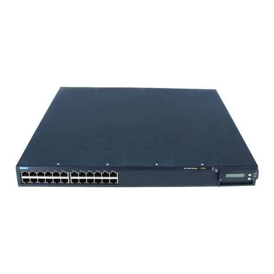
Juniper EX 3200 Quick Start
Hide thumbs
Also See for EX 3200:
- Manual (4 pages) ,
- Complete hardware manual (194 pages) ,
- Connecting (4 pages)
Advertisement
Quick Links
EX 3200 and EX 4200 Switch Quick Start
To install and configure an EX 3200 or EX 4200 switch, you need:
Two mounting brackets and eight mounting screws (provided)
If your system order includes an AC power supply—a power cord with a plug
appropriate for your geographical location and a power cord retainer (provided)
If your system order includes a DC power supply—DC power source cables (12–14
AWG) with ring lug (Molex 190700067 or equivalent) (not provided)
Screwdriver to remove and tighten screws (Phillips (+) screwdriver, number 2)
Electrostatic discharge (ESD) grounding strap
Management host, such as a PC, with an Ethernet port
Ethernet cable (provided)
For more information about the tasks described in this quick start and other setup tasks,
see the EX-series documentation at
Part 1: Install a Power Supply in the Switch (If It Is Not Installed)
To install each power supply in the switch chassis:
1.
Remove the power supply from the bag. Take care not to touch power supply
components, pins, leads, or solder connections.
2.
Push down on the locking lever on the left front of the power supply until it is in its
lowest position (see the figure in Part 3 for the location of the locking lever). You might
need to loosen the locking lever screw to move the lever.
3.
Using both hands, place the power supply in the power supply slot on the rear panel
of the switch and slide it in until it is fully seated.
4.
Push the locking lever up to its highest position (this action might pull the power
supply in). Tighten the locking lever screw using a Phillips (+) screwdriver, number 2.
Part 2: Install the Switch
1.
Attach an ESD grounding strap to your bare wrist and connect the strap to an outside
ESD point.
2.
Attach the mounting brackets to the switch chassis by using mounting screws.
3.
Make sure the rack is properly secured to the building in its permanent location.
4.
Have one person grasp both sides of the switch, lift the switch, and position it in the
rack, aligning the bracket holes with the threaded holes in the rack.
5.
Have a second person install a mounting screw into each of the bracket holes.
Part 3: Connect Power to the Switch
NOTE:
If you are interconnecting multiple switches as a virtual chassis, power on only one
switch—the one you will use as the master.
.
http://www.juniper.net/techpubs/
To connect AC power to the switch:
1.
Squeeze the two sides of the power cord retainer clip, and insert the L-shaped ends of
the wire clip into the holes in the bracket on each side of the AC appliance inlet on the
power supply faceplate.
Locking
AC
lever
D C
Retainer clip
Adjustment nut
2.
Insert the coupler end of the power cord into the AC appliance inlet.
3.
Push the cord into the slot in the adjustment nut of the power cord retainer. Turn the
nut until it is tight against the base of the coupler and the slot in the nut is turned 90°
from the top of the switch.
4.
If the AC power source outlet has a power switch, set it to the OFF (0) position.
5.
Insert the power cord plug into the power source outlet.
6.
If the AC power source outlet has a power switch, set it to the ON (|) position.
7.
Repeat these steps for each AC power supply.
To connect DC power to the switch:
Each DC power supply has four terminals labeled A+, A–, B+, and B–. The power supply
is shipped with jumpers from A+ input to B+ input tied together and jumpers from A–
input to B– input tied together.
WARNING
: On each power supply, ensure that the input circuit breaker is open so that the
voltage across the DC power source cable leads is 0 V and that the cable leads will not
become active while you are connecting DC power.
1.
On each power supply, remove the screw that secures the terminal block cover and
remove the cover. Save the screw.
2.
Connect the power supplies to the power sources. Secure power source cables to the
power supplies by screwing the ring lug attached to the cable to the appropriate
terminal (use the screw from the terminal).
To connect a power supply to a power source: Leave the jumpers in place and
secure the positive power source cable to the A+ terminal and the negative
power source cable to the A– terminal.
If you have a second installed power supply, connect it in the same way you did
the first.
Tighten
adjustment nut.
A C
D C
Advertisement

Summary of Contents for Juniper EX 3200
- Page 1 EX 3200 and EX 4200 Switch Quick Start To install and configure an EX 3200 or EX 4200 switch, you need: To connect AC power to the switch: Two mounting brackets and eight mounting screws (provided) Squeeze the two sides of the power cord retainer clip, and insert the L-shaped ends of the wire clip into the holes in the bracket on each side of the AC appliance inlet on the If your system order includes an AC power supply—a power cord with a plug...
- Page 2 Inc. All other trademarks, service marks, registered trademarks, or registered service marks are the property of their respective owners. Juniper Networks assumes no responsibility for any inaccuracies in this document. Juniper Networks reserves the right to change, modify, transfer, or otherwise revise this publication without notice. Products made or sold by Juniper Networks or components thereof might be covered by one or more of the following patents that are owned by or licensed to Juniper Networks: U.S.


