Sign In
Upload
Manuals
Brands
Juniper Manuals
Switch
EX3200 Series
Juniper EX3200 Series Manuals
Manuals and User Guides for Juniper EX3200 Series. We have
10
Juniper EX3200 Series manuals available for free PDF download: Hardware Manual, Complete Hardware Manual, Brochure, Quick Start Manual, Datasheet, Connecting, Installing, Mounting
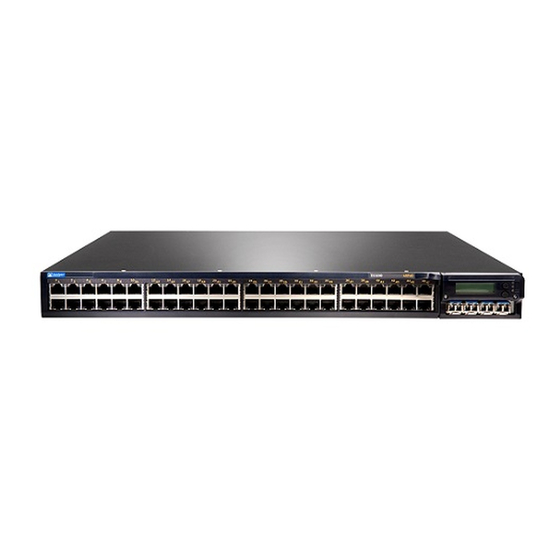
Juniper EX3200 Series Hardware Manual (354 pages)
Junos OSfor EXSeries EthernetSwitches
Brand:
Juniper
| Category:
Switch
| Size: 3.41 MB
Table of Contents
Table of Contents
3
About the Documentation
15
Documentation and Release Notes
15
Supported Platforms
15
Using the Examples in this Manual
15
Merging a Full Example
16
Merging a Snippet
16
Documentation Conventions
17
About the Documentation
17
Table 1: Notice Icons
17
Table 2: Text and Syntax Conventions
17
Documentation Feedback
19
Requesting Technical Support
19
Self-Help Online Tools and Resources
19
Opening a Case with JTAC
20
Overview
21
Interfaces Overview
21
Chapter 1 Interfaces Overview
23
Interfaces Overview
23
EX Series Switches Interfaces Overview
23
Network Interfaces
23
Special Interfaces
24
Table 3: Network Interface Types and Purposes
24
Table 4: Special Interface Types and Purposes
24
Understanding Interface Naming Conventions on EX Series Switches
26
Physical Part of an Interface Name
26
Logical Part of an Interface Name
28
Wildcard Characters in Interface Names
28
Understanding Aggregated Ethernet Interfaces and LACP
28
Link Aggregation Group (LAG)
29
Table 5: Maximum Interfaces Per LAG and Maximum Lags Per Switch
29
Link Aggregation Control Protocol (LACP)
30
ECMP Traffic
31
Understanding the Hashing Algorithm
31
IP (Ipv4 and Ipv6)
32
Table 6: Ipv4 and Ipv6 Hashing Fields
33
Mpls
34
Table 7: MPLS Hashing Fields
34
MAC-In-MAC Packet Hashing
35
Layer 2 Header Hashing
35
Table 8: MAC-In-MAC Hashing Fields
35
Table 9: Layer 2 Header Hashing Fields
35
Understanding How Energy Efficient Ethernet Reduces Power Consumption on
36
Interfaces
36
Understanding Local Link Bias
36
Figure 1: Egress Traffic Flow with Local Link Bias
37
Figure 2: Egress Traffic Flow Without Local Link Bias
37
Understanding Layer 3 Subinterfaces
38
Understanding Unicast RPF
39
Unicast RPF for Switches Overview
39
Unicast RPF Implementation
40
Unicast RPF Packet Filtering
40
Bootstrap Protocol (BOOTP) and DHCP Requests
40
Default Route Handling
40
When to Enable Unicast RPF
40
When Not to Enable Unicast RPF
41
Figure 3: Symmetrically Routed Interfaces
41
Limitations of the Unicast RPF Implementation on EX3200, EX4200, and EX4300 Switches
42
Figure 4: Asymmetrically Routed Interfaces
42
Understanding IP Directed Broadcast for EX Series Switches
43
IP Directed Broadcast for EX Series Switches Overview
43
IP Directed Broadcast Implementation for EX Series Switches
43
When to Enable IP Directed Broadcast
44
When Not to Enable IP Directed Broadcast
44
Understanding Interface Ranges on EX Series Switches
44
802.1Q Vlans Overview
46
Configuration
49
Part 2 Configuration
49
Chapter 2 Configuration Tasks
51
Configuring Gigabit Ethernet Interfaces (CLI Procedure)
52
Configuring VLAN Options and Interface Mode
52
Configuring the Link Settings
53
Configuration Tasks
53
Table 10: Factory Default Configuration Link Settings for EX Series Switches
53
Configuring the IP Options
54
Configuring Gigabit Ethernet Interfaces (J-Web Procedure)
55
Table 11: Port Edit Options
57
Table 12: Recommended Cos Settings for Port Roles
60
Port Role Configuration with the J-Web Interface (with CLI References)
61
Table 13: Port Role Configuration Summary
61
Table 14: Recommended Cos Settings for Port Roles
64
Adding a Logical Unit Description to the Configuration
65
Disabling a Physical Interface
65
Example: Disabling a Physical Interface
66
Disabling a Logical Interface
67
Configuring Flow Control
67
Configuring the Interface Address
68
Configuring Interface Ipv4 Addresses
69
Operational Behavior of Interfaces When the same Ipv4 Address Is Assigned to Them
70
Configuring Interface Ipv6 Addresses
71
Configuring the Interface Bandwidth
72
Configuring the Media MTU
73
Media MTU Overview
74
How to Configure the Media MTU
75
Encapsulation Overhead by Encapsulation Type
76
Table 15: Encapsulation Overhead by Encapsulation Type
76
Media MTU Sizes by Interface Type for M5 and M7I Routers with CFEB, M10 and M10I Routers with CFEB, and M20 and M40 Routers
77
Media MTU Sizes by Interface Type for M40E Routers
77
Table 16: Media MTU Sizes by Interface Type for M5 and M7I Routers with CFEB, M10 and M10I Routers with CFEB, and M20 and M40 Routers
77
Table 17: Media MTU Sizes by Interface Type for M40E Routers
77
Media MTU Sizes by Interface Type for M160 Routers
79
Media MTU Sizes by Interface Type for M7I Routers with CFEB-E, M10I Routers with CFEB-E, and M320 and M120 Routers
79
Table 18: Media MTU Sizes by Interface Type for M160 Routers
79
Table 19: Media MTU Sizes by Interface Type for M7I Routers with CFEB-E, M10I Routers with CFEB-E, and M320 and M120 Routers
79
Media MTU Sizes by Interface Type for MX Series Routers
80
Table 20: Media MTU Sizes by Interface Type for MX Series Routers
80
Media MTU Sizes by Interface Type for T320 Routers
81
Media MTU Sizes by Interface Type for T640 Platforms
81
Table 21: Media MTU Sizes by Interface Type for T320 Routers
81
Table 22: Media MTU Sizes by Interface Type for T640 Platforms
81
Media MTU Sizes by Interface Type for J2300 Platforms
82
Media MTU Sizes by Interface Type for J4300 and J6300 Platforms
82
Table 23: Media MTU Sizes by Interface Type for J2300 Platforms
82
Table 24: Media MTU Sizes by Interface Type for J4300 and J6300
82
Media MTU Sizes by Interface Type for J4350 and J6350 Platforms
83
Table 25: Media MTU Sizes by Interface Type for J4350 and J6350
83
Media MTU Sizes by Interface Type for EX Series Switches and ACX Series Routers
85
Media MTU Sizes by Interface Type for PTX Series Packet Transport Routers
85
Setting the Protocol MTU
85
Table 26: Media MTU Sizes by Interface Type for EX Series Switches and ACX
85
Table 27: Media MTU Sizes by Interface Type for PTX Series Packet Transport
85
Interface Ranges
86
Configuring Interface Ranges
87
Expanding Interface Range Member and Member Range Statements
89
Configuration Inheritance for Member Interfaces
90
Member Interfaces Inheriting Configuration from Configuration Groups
91
Interfaces Inheriting Common Configuration
93
Configuring Inheritance Range Priorities
93
Configuration Expansion Where Interface Range Is Used
93
Configuring Accounting for the Physical Interface
94
Applying an Accounting Profile to the Physical Interface
95
Example: Applying an Accounting Profile to the Physical Interface
95
Configuring Accounting for the Logical Interface
96
Applying an Accounting Profile to the Logical Interface
96
Example: Applying an Accounting Profile to the Logical Interface
96
Configuring Ethernet Loopback Capability
97
Configuring Gratuitous ARP
98
Configuring Static ARP Table Entries
99
Example: Configuring Static ARP Table Entries
99
Disabling the Transmission of Redirect Messages on an Interface
100
Configuring Restricted and Unrestricted Proxy ARP
100
Enabling or Disabling SNMP Notifications on Logical Interfaces
101
Configuring Aggregated Ethernet Links (CLI Procedure)
102
Configuring Aggregated Ethernet Interfaces (J-Web Procedure)
103
Table 28: Aggregated Ethernet Interface Options
104
Table 29: VLAN Options
105
Table 30: IP Options
105
Configuring Aggregated Ethernet LACP (CLI Procedure)
106
Configuring LACP Link Protection of Aggregated Ethernet Interfaces
107
Procedure)
108
Configuring LACP Link Protection at the Global Level
108
Configuring LACP Link Protection at the Aggregated Interface Level
108
Configuring Aggregated Ethernet Link Protection
109
Configuring Link Protection for Aggregated Ethernet Interfaces
109
Configuring Primary and Backup Links for Link Aggregated Ethernet
109
Interfaces
109
Reverting Traffic to a Primary Link When Traffic Is Passing through a Backup Link
110
Disabling Link Protection for Aggregated Ethernet Interfaces
110
Configuring Aggregated Ethernet Link Speed
110
Configuring Aggregated Ethernet Minimum Links
112
Configuring Energy Efficient Ethernet on Interfaces (CLI Procedure)
113
Enabling EEE on an EEE-Capable Base-T Copper Ethernet Port
113
Disabling EEE on a Base-T Copper Ethernet Port
113
Configuring Local Link Bias (CLI Procedure)
114
Configuring the Fields in the Algorithm Used to Hash LAG Bundle and ECMP Traffic (CLI Procedure)
114
Configuring the Hashing Algorithm to Use Fields in the Layer 2 Header for Hashing
115
Hashing
115
Hashing
116
Configuring Tagged Aggregated Ethernet Interfaces
116
Configuring a Layer 3 Subinterface (CLI Procedure)
117
Configuring Unicast RPF (CLI Procedure)
117
Disabling Unicast RPF (CLI Procedure)
119
Configuring IP Directed Broadcast (CLI Procedure)
120
Tracing Operations of an Individual Router or Switch Interface
121
Tracing Operations of the Interface Process
121
Configuration Tasks
51
Advertisement
Juniper EX3200 Series Hardware Manual (310 pages)
Brand:
Juniper
| Category:
Switch
| Size: 4.3 MB
Table of Contents
Table of Contents
3
About the Documentation
17
Documentation and Release Notes
17
Supported Platforms
17
Documentation Conventions
17
Table 1: Notice Icons
18
Table 2: Text and Syntax Conventions
18
Documentation Feedback
19
About the Documentation
19
Requesting Technical Support
20
Self-Help Online Tools and Resources
20
Opening a Case with JTAC
20
Overview
23
System Overview
23
Chassis Components and Descriptions
23
Power Supplies
23
Chapter 1 System Overview
25
System Overview
25
EX3200 Switches Hardware Overview
25
EX3200 Switches
25
EX3200 Switch Models
26
Power over Ethernet (Poe) Ports
26
Uplink Modules
26
EX3200 Switch Hardware and CLI Terminology Mapping
27
Table 3: EX3200 Switch Models
27
Table 4: CLI Equivalents of Terms Used in Documentation for EX3200
27
Switches
28
Chapter 2 Chassis Components and Descriptions
29
Chassis Physical Specifications for EX3200 Switches
29
Table 5: Physical Specifications of the Switch Chassis
29
Field-Replaceable Units in EX3200 Switches
30
Front Panel of an EX3200 Switch
31
Chassis Components and Descriptions
31
Figure 1: EX3200 Switch with 48 Gigabit Ethernet Ports
31
Figure 2: EX3200 Switch with 24 Gigabit Ethernet Ports
31
Figure 3: EX3200 Switch Rear Panel
32
Rear Panel of an EX3200 Switch
32
LCD Panel in EX3200 Switches
33
LCD Panel Modes
33
Figure 4: LCD Panel
33
LCD Panel Menus
34
Table 6: LCD Panel Menu Options
34
Uplink Modules in EX3200 Switches
37
SFP Uplink Module
38
SFP+ Uplink Module and SFP+ Macsec Uplink Module
38
Figure 5: SFP Uplink Module
38
Figure 6: SFP+ and SFP+ Macsec Uplink Module
39
XFP Uplink Module
40
Chassis Status Leds in EX3200 Switches
40
Figure 7: XFP Uplink Module
40
Figure 8: Chassis Status Leds in an EX3200 Switch
41
Table 7: Chassis Status Leds in an EX3200 Switch
41
Figure 9: Leds on the Management Port on an EX3200 Switch
42
Management Port Leds in EX3200 Switches
42
Table 8: Link/Activity LED on the Management Port on EX3200 Switches
42
Table 9: Status LED on the Management Port on EX3200 Switches
42
Figure 10: Leds on the Network Ports on the Front Panel
43
Figure 11: Leds on the Uplink Module Ports on the SFP Uplink Module
43
Network Port Leds in EX3200 Switches
43
Figure 12: Leds on the Uplink Module Ports on the SFP+ and SFP+ Macsec Uplink
44
Figure 13: Leds on the Uplink Module Ports on the XFP Uplink Module
44
Modules
44
Table 10: Link/Activity LED on Network Ports
44
Table 11: Status LED on Network Ports
46
Chapter 3 Cooling System and Airflow
49
Cooling System and Airflow in an EX3200 Switch
49
Fan Tray
49
Airflow Direction in the EX3200 Switch Chassis
49
Figure 14: Fan Tray Used in an EX3200 Switch
49
Figure 15: Airflow through the EX3200 Switch Chassis
50
Chapter 4 Power Supplies
51
DC Power Supplies
52
Figure 16: 320 W AC Power Supply
52
Figure 17: 600 W and 930 W AC Power Supplies
52
Poe Power Budget and AC Power Supplies
53
Figure 18: DC Power Supply
53
AC Power Supply Leds in EX3200 Switches
54
Table 12: Power Supply Rating and Poe Power Budget for EX3200 Switch
54
Table 13: AC Power Supply Leds
54
DC Power Supply Leds in EX3200 Switches
55
Table 14: DC Power Supply Leds
55
Power Supplies
51
Power Supply in EX3200 Switches
51
AC Power Supplies
51
Chapter 5 Viewing System Information
57
Dashboard for EX Series Switches
57
Graphical Chassis Viewer
58
Table 15: Details of a Virtual Chassis Member Switch
58
Table 16: Status of a Member Switch in a Virtual Chassis
58
System Information Panel
59
Viewing System Information
59
Table 17: System Information
59
Health Status Panel
61
Table 18: Health Status
61
Capacity Utilization Panel
63
Alarms Panel
63
Table 19: Capacity Utilization
63
File System Usage
64
Chassis Viewer
64
Table 20: Chassis Viewer for EX2200 Switches
64
Table 21: Chassis Viewer for EX2200-C and EX2300-C Switches
65
Table 22: Chassis Viewer for EX2300 Switches
66
Table 23: Chassis Viewer for EX3200, EX3300, and EX4200 Switches
67
Table 24: Chassis Viewer for EX3400 and EX4300 Switches
68
Table 25: Chassis Viewer for EX4500 Switches
70
Table 26: Chassis Viewer for EX4550 Switches
71
Table 27: Chassis Viewer for EX6210 Switches
72
Table 28: Chassis Viewer for EX8208 Switches
72
Table 29: Chassis Viewer for EX8216 Switches
74
Table 30: Chassis Viewer for XRE200 External Routing Engines
74
Site Planning, Preparation, and Specifications
77
Preparation Overview
77
Chapter 6 Preparation Overview
79
Environmental Requirements and Specifications for EX Series Switches
80
Table 32: EX Series Switch Environmental Tolerances
81
General Site Guidelines
84
Site Electrical Wiring Guidelines
85
Table 33: Site Electrical Wiring Guidelines
85
Rack Requirements
86
Table 34: Rack Requirements and Specifications
86
Cabinet Requirements
87
Requirements for Mounting an EX3200 Switch on a Desktop or Wall
87
Table 35: Cabinet Requirements and Specifications
87
Figure 19: Clearance Requirements for Airflow and Hardware Maintenance for
88
Figure 20: Airflow through the EX3200 Switch Chassis
89
Switches
91
Preparation Overview
79
Site Preparation Checklist for EX3200 Switches
79
Table 31: Site Preparation Checklist
79
Chapter 7 Power Specifications and Requirements
91
AC Power Cord Specifications for EX3200 Switches
92
Figure 21: AC Plug Types
93
Table 38: AC Power Cord Specifications
93
Calculating the EX Series Switch Fiber-Optic Cable Power Budget
94
Calculating the EX Series Switch Fiber-Optic Cable Power Margin
94
Power Specifications and Requirements
95
Table 39: Estimated Values for Factors Causing Link Loss
95
Power Specifications and Requirements
91
Power Specifications for EX3200 Switches
91
Table 36: AC Power Supply Electrical Specifications
91
Table 37: DC Power Supply Electrical Specifications
91
Chapter 8 Transceiver and Cable Specifications
97
Pluggable Transceivers Supported on EX3200 Switches
97
Table 40: Optical Interface Support and Copper Interface Support for Gigabit Ethernet SFP Transceivers in EX3200 Switches
98
Transceiver and Cable Specifications
99
Table 41: Optical Interface Support for Fast Ethernet SFP Transceivers in EX3200
117
Table 42: Optical Interface Support for Gigabit Ethernet SFP+ Transceivers in
123
Table 43: Optical Interface Support for Gigabit Ethernet XFP Transceivers in
128
Pluggable Transceivers Supported on EX Series Switches
131
SFP+ Direct Attach Copper Cables for EX Series Switches
133
Cable Specifications
133
Figure 22: SFP+ Direct Attach Copper Cables for EX Series Switches
133
Table 44: Software Support for SFP+ Passive Direct Attach Copper Cables for
133
Table 45: SFP+ Direct Attach Copper Cable Specifications
135
Standards Supported by These Cables
137
Management Cable Specifications
137
Understanding EX Series Switches Fiber-Optic Cable Signal Loss, Attenuation
138
And Dispersion
138
Signal Loss in Multimode and Single-Mode Fiber-Optic Cable
138
Table 46: Specifications of Cables to Connect to Management Devices
138
Attenuation and Dispersion in Fiber-Optic Cable
139
Chapter 9 Pinout Specifications
141
USB Port Specifications for an EX Series Switch
142
RJ-45 Management Port Connector Pinout Information
143
Port, QSFP+ Port, SFP+ Port, and SFP Port Connector Pinout Information
143
Table 48: RJ-45 Management Port Connector Pinout Information
143
Table 49: 10/100/1000BASE-T Ethernet Network Port Connector Pinout
144
Table 50: SFP Network Port Connector Pinout Information
144
Table 51: SFP+ Network Port Connector Pinout Information
145
Table 52: QSFP+ Network Port Connector Pinout Information
146
RJ-45 to DB-9 Serial Port Adapter Pinout Information
148
Uplink Modules Connector Pinout Information for EX3200 Switches
148
Table 53: RJ-45 to DB-9 Serial Port Adapter Pinout Information
148
Table 54: Uplink Modules Connector Pinout Information
149
Part 3 Initial Installation and Configuration
157
Pinout Specifications
141
Console Port Connector Pinout Information
141
Table 47: Console Port Connector Pinout Information
141
Chapter 10 Unpacking the Switch
159
Unpacking an EX3200 Switch
159
Parts Inventory (Packing List) for an EX3200 Switch
160
Figure 23: Unpacking an EX3200 Switch
160
Registering Products-Mandatory for Validating Slas
161
Table 55: Packing List for an EX3200 Switch
161
Chapter 11 Installing the Switch
163
Installing and Connecting an EX3200 Switch
163
Mounting an EX3200 Switch
164
Mounting an EX3200 Switch on a Desk or Other Level Surface
165
Figure 24: Attaching Rubber Feet to an EX3200 Switch Chassis
165
Mounting an EX3200 Switch on Two Posts in a Rack or Cabinet
166
Figure 25: Attaching the Mounting Bracket to the Side Panel of the Switch
167
Mounting an EX3200 Switch on Four Posts in a Rack or Cabinet
168
Figure 26: Mounting the Switch on Two Posts in a Rack
168
Figure 27: Attaching the Front-Mounting Bracket to the Side Mounting-Rail
170
Figure 28: Attaching the Side Mounting-Rail to the Switch Chassis
170
Figure 29: Mounting the Switch to the Front Posts in a Rack
171
Figure 30: Sliding the Rear Mounting-Blades into the Side-Mounting Rail
171
Mounting an EX3200 Switch in a Recessed Position in a Rack or Cabinet
172
Mounting an EX3200 Switch on a Wall
172
Figure 31: Attaching Wall-Mount Brackets to the Switch Chassis
173
Installing and Removing EX3200 Switch Hardware Components
174
Figure 32: Mounting the Switch on a Wall
174
Chapter 12 Connecting the Switch to Power
177
Connecting Earth Ground to an EX Series Switch
177
Parts and Tools Required for Connecting an EX Series Switch to Earth Ground
177
Table 56: Parts and Tools Required for Connecting an EX Series Switch to Earth Ground
178
Special Instructions to Follow before Connecting Earth Ground to a
178
Special Instructions to Follow before Connecting Earth Ground to a
179
Connecting Earth Ground to an EX Series Switch
182
Figure 34: Connecting a Grounding Cable to an EX Series Switch
182
Chapter 13 Switch
180
Figure 33: Connecting the Grounding Lug to a Switch Mounted on Four Posts of
181
Connecting AC Power to an EX3200 Switch
183
Connecting DC Power to an EX3200 Switch
185
Figure 35: Connecting the AC Power Cord Retainer Clip to an AC Power Supply in an EX3200 Switch
185
Figure 36: Connecting an AC Power Cord to an AC Power Supply in an EX3200 Switch
185
Figure 37: DC Power Supply in an EX3200 Switch
185
Figure 38: Removing the Terminal Block Cover from a DC Power Supply
187
Figure 39: Securing Ring Lugs to the Terminals on the DC Power Supply
188
Connecting the Switch to the Network
189
Connecting a Device to a Network for Out-Of-Band Management
189
Connecting a Device to a Management Console by Using an
189
Figure 40: RJ-45 Connector on an Ethernet Cable
189
Connector
190
Figure 41: Connecting a Device to a Network for Out-Of-Band Management
190
Figure 42: RJ-45 Connector on an Ethernet Cable
190
Connecting a Fiber-Optic Cable
191
Figure 43: Connecting a Device to a Management Console through a Console
191
Figure 44: Connecting a Device Directly to a Management Console
191
A Device
192
Figure 45: Connecting a Fiber-Optic Cable to an Optical Transceiver Installed in
192
Juniper EX3200 Series Hardware Manual (280 pages)
Brand:
Juniper
| Category:
Switch
| Size: 4.17 MB
Table of Contents
Table of Contents
3
About the Documentation
17
Documentation and Release Notes
17
Supported Platforms
17
Documentation Conventions
17
Table 1: Notice Icons
18
Table 2: Text and Syntax Conventions
18
Documentation Feedback
19
About the Documentation
19
Requesting Technical Support
20
Self-Help Online Tools and Resources
20
Opening a Case with JTAC
20
Overview
23
System Overview
23
Chassis Components and Descriptions
23
Power Supplies
23
Chapter 1 System Overview
25
System Overview
25
EX3200 Switches Hardware Overview
25
EX3200 Switches
25
EX3200 Switch Models
26
Power over Ethernet (Poe) Ports
26
Uplink Modules
26
EX3200 Switch Hardware and CLI Terminology Mapping
27
Table 3: EX3200 Switch Models
27
Table 4: CLI Equivalents of Terms Used in Documentation for EX3200
27
Switches
28
Chapter 2 Chassis Components and Descriptions
29
Chassis Physical Specifications for EX3200 Switches
29
Table 5: Physical Specifications of the Switch Chassis
29
Field-Replaceable Units in EX3200 Switches
30
Front Panel of an EX3200 Switch
31
Chassis Components and Descriptions
31
Figure 1: EX3200 Switch with 48 Gigabit Ethernet Ports
31
Figure 2: EX3200 Switch with 24 Gigabit Ethernet Ports
31
Figure 3: EX3200 Switch Rear Panel
32
Rear Panel of an EX3200 Switch
32
LCD Panel in EX3200 Switches
33
LCD Panel Modes
33
Figure 4: LCD Panel
33
LCD Panel Menus
34
Table 6: LCD Panel Menu Options
34
Uplink Modules in EX3200 Switches
37
SFP Uplink Module
38
SFP+ Uplink Module and SFP+ Macsec Uplink Module
38
Figure 5: SFP Uplink Module
38
Figure 6: SFP+ and SFP+ Macsec Uplink Module
39
XFP Uplink Module
40
Chassis Status Leds in EX3200 Switches
40
Figure 7: XFP Uplink Module
40
Figure 8: Chassis Status Leds in an EX3200 Switch
41
Table 7: Chassis Status Leds in an EX3200 Switch
41
Figure 9: Leds on the Management Port on an EX3200 Switch
42
Management Port Leds in EX3200 Switches
42
Table 8: Link/Activity LED on the Management Port on EX3200 Switches
42
Figure 10: Leds on the Network Ports on the Front Panel
43
Network Port Leds in EX3200 Switches
43
Table 9: Status LED on the Management Port on EX3200 Switches
43
Figure 11: Leds on the Uplink Module Ports on the SFP Uplink Module
44
Figure 12: Leds on the Uplink Module Ports on the SFP+ and SFP+ Macsec Uplink
44
Figure 13: Leds on the Uplink Module Ports on the XFP Uplink Module
44
Table 10: Link/Activity LED on Network Ports
45
Table 11: Status LED on Network Ports
46
Chapter 3 Cooling System and Airflow
49
Cooling System and Airflow in an EX3200 Switch
49
Fan Tray
49
Airflow Direction in the EX3200 Switch Chassis
49
Figure 14: Fan Tray Used in an EX3200 Switch
49
Figure 15: Airflow through the EX3200 Switch Chassis
50
Chapter 4 Power Supplies
51
DC Power Supplies
52
Figure 16: 320 W AC Power Supply
52
Figure 17: 600 W and 930 W AC Power Supplies
52
Poe Power Budget and AC Power Supplies
53
Figure 18: DC Power Supply
53
AC Power Supply Leds in EX3200 Switches
54
Table 12: Power Supply Rating and Poe Power Budget for EX3200 Switch
54
Table 13: AC Power Supply Leds
54
DC Power Supply Leds in EX3200 Switches
55
Table 14: DC Power Supply Leds
55
Power Supplies
51
Power Supply in EX3200 Switches
51
AC Power Supplies
51
Chapter 5 Viewing System Information
57
Dashboard for EX Series Switches
57
Graphical Chassis Viewer
58
Table 15: Details of a Virtual Chassis Member Switch
58
System Information Panel
59
Viewing System Information
59
Table 16: Status of a Member Switch in a Virtual Chassis
59
Table 17: System Information
59
Health Status Panel
61
Table 18: Health Status
61
Capacity Utilization Panel
63
Alarms Panel
63
Table 19: Capacity Utilization
63
File System Usage
64
Chassis Viewer
64
Table 20: Chassis Viewer for EX2200 Switches
64
Table 21: Chassis Viewer for EX2200-C Switches
65
Table 22: Chassis Viewer for EX3200, EX3300, and EX4200 Switches
65
Table 23: Chassis Viewer for EX4300 Switches
67
Table 24: Chassis Viewer for EX4500 Switches
68
Table 25: Chassis Viewer for EX4550 Switches
69
Table 26: Chassis Viewer for EX4600 Switches
71
Table 27: Chassis Viewer for EX6210 Switches
71
Table 28: Chassis Viewer for EX8208 Switches
72
Table 29: Chassis Viewer for EX8216 Switches
74
Table 30: Chassis Viewer for XRE200 External Routing Engines
74
Site Planning, Preparation, and Specifications
77
Preparation Overview
77
Transceiver and Cable Specifications
77
Chapter 6 Preparation Overview
79
Environmental Requirements and Specifications for EX Series Switches
80
Table 32: EX Series Switch Environmental Tolerances
81
General Site Guidelines
84
Site Electrical Wiring Guidelines
85
Table 33: Site Electrical Wiring Guidelines
85
Rack Requirements
86
Cabinet Requirements
86
Table 34: Rack Requirements and Specifications
86
Requirements for Mounting an EX3200 Switch on a Desktop or Wall
87
Table 35: Cabinet Requirements and Specifications
87
Figure 19: Clearance Requirements for Airflow and Hardware Maintenance for
88
Figure 20: Airflow through the EX3200 Switch Chassis
89
Switches
91
Preparation Overview
79
Site Preparation Checklist for EX3200 Switches
79
Table 31: Site Preparation Checklist
79
Chapter 7 Power Specifications and Requirements
91
AC Power Cord Specifications for EX3200 Switches
92
Figure 21: AC Plug Types
93
Table 38: AC Power Cord Specifications
93
Calculating the EX Series Switch Fiber-Optic Cable Power Budget
94
Calculating the EX Series Switch Fiber-Optic Cable Power Margin
94
Power Specifications and Requirements
95
Table 39: Estimated Values for Factors Causing Link Loss
95
Power Specifications and Requirements
91
Power Specifications for EX3200 Switches
91
Table 36: AC Power Supply Electrical Specifications
91
Table 37: DC Power Supply Electrical Specifications
91
Chapter 8 Transceiver and Cable Specifications
97
Pluggable Transceivers Supported on EX3200 Switches
97
Pluggable Transceivers Supported on EX Series Switches
98
SFP+ Direct Attach Copper Cables for EX Series Switches
99
Cable Specifications
99
Figure 22: SFP+ Direct Attach Copper Cables for EX Series Switches
99
Table 40: Software Support for SFP+ Passive Direct Attach Copper Cables for EX Series Switches
99
Table 41: SFP+ Direct Attach Copper Cable Specifications
102
Standards Supported by These Cables
105
Management Cable Specifications
105
Understanding EX Series Switches Fiber-Optic Cable Signal Loss, Attenuation
106
And Dispersion
106
Signal Loss in Multimode and Single-Mode Fiber-Optic Cable
106
Table 42: Specifications of Cables to Connect to Management Devices
106
Attenuation and Dispersion in Fiber-Optic Cable
107
Chapter 9 Pinout Specifications
109
USB Port Specifications for an EX Series Switch
110
RJ-45 Management Port Connector Pinout Information
111
Table 44: RJ-45 Management Port Connector Pinout Information
111
Port, QSFP+ Port, SFP+ Port, and SFP Port Connector Pinout Information
112
Table 45: 10/100/1000BASE-T Ethernet Network Port Connector Pinout
112
Table 46: SFP Network Port Connector Pinout Information
112
Table 47: SFP+ Network Port Connector Pinout Information
113
Table 48: QSFP+ Network Port Connector Pinout Information
114
RJ-45 to DB-9 Serial Port Adapter Pinout Information
116
Table 49: RJ-45 to DB-9 Serial Port Adapter Pinout Information
116
Uplink Modules Connector Pinout Information for EX3200 Switches
117
Table 50: Uplink Modules Connector Pinout Information
117
Part 3 Initial Installation and Configuration
125
Pinout Specifications
109
Console Port Connector Pinout Information
109
Table 43: Console Port Connector Pinout Information
109
Chapter 10 Unpacking the Switch
127
Unpacking an EX3200 Switch
127
Parts Inventory (Packing List) for an EX3200 Switch
128
Figure 23: Unpacking an EX3200 Switch
128
Registering Products-Mandatory for Validating Slas
129
Table 51: Packing List for an EX3200 Switch
129
Chapter 11 Installing the Switch
131
Installing and Connecting an EX3200 Switch
131
Mounting an EX3200 Switch
132
Mounting an EX3200 Switch on a Desk or Other Level Surface
133
Mounting an EX3200 Switch on Two Posts in a Rack or Cabinet
134
Figure 24: Attaching Rubber Feet to an EX3200 Switch Chassis
134
Figure 25: Attaching the Mounting Bracket to the Side Panel of the Switch
135
Mounting an EX3200 Switch on Four Posts in a Rack or Cabinet
136
Figure 26: Mounting the Switch on Two Posts in a Rack
136
Figure 27: Attaching the Front-Mounting Bracket to the Side Mounting-Rail
138
Figure 28: Attaching the Side Mounting-Rail to the Switch Chassis
138
Figure 29: Mounting the Switch to the Front Posts in a Rack
139
Figure 30: Sliding the Rear Mounting-Blades into the Side-Mounting Rail
139
Mounting an EX3200 Switch in a Recessed Position in a Rack or Cabinet
140
Mounting an EX3200 Switch on a Wall
140
Figure 31: Attaching Wall-Mount Brackets to the Switch Chassis
142
Installing and Removing EX3200 Switch Hardware Components
143
Figure 32: Mounting the Switch on a Wall
143
Chapter 12 Connecting the Switch to Power
145
Connecting Earth Ground to an EX Series Switch
145
Parts and Tools Required for Connecting an EX Series Switch to Earth Ground
145
Table 52: Parts and Tools Required for Connecting an EX Series Switch to Earth
146
Special Instructions to Follow before Connecting Earth Ground to a
146
Special Instructions to Follow before Connecting Earth Ground to a
147
Connecting Earth Ground to an EX Series Switch
150
Figure 34: Connecting a Grounding Cable to an EX Series Switch
150
Chapter 13 Switch
148
Table 53: Special Instructions to Follow before Connecting Earth Ground to a
148
Figure 33: Connecting the Grounding Lug to a Switch Mounted on Four Posts of
149
Connecting AC Power to an EX3200 Switch
151
Connecting DC Power to an EX3200 Switch
153
Figure 35: Connecting the AC Power Cord Retainer Clip to an AC Power Supply in an EX3200 Switch
153
Figure 36: Connecting an AC Power Cord to an AC Power Supply in an EX3200 Switch
153
Figure 37: DC Power Supply in an EX3200 Switch
154
Figure 38: Removing the Terminal Block Cover from a DC Power Supply
155
Figure 39: Securing Ring Lugs to the Terminals on the DC Power Supply
157
Connecting the Switch to the Network
159
Connecting a Device to a Network for Out-Of-Band Management
159
Connecting a Device to a Management Console by Using an
159
Figure 40: RJ-45 Connector on an Ethernet Cable
159
Connector
160
Figure 41: Connecting a Device to a Network for Out-Of-Band Management
160
Figure 42: RJ-45 Connector on an Ethernet Cable
160
Connecting a Fiber-Optic Cable
161
Figure 43: Connecting a Device to a Management Console through a Console
161
Figure 44: Connecting a Device Directly to a Management Console
161
A Device
162
Figure 45: Connecting a Fiber-Optic Cable to an Optical Transceiver Installed in
162
Advertisement
Juniper EX3200 Series Complete Hardware Manual (280 pages)
Brand:
Juniper
| Category:
Switch
| Size: 4.56 MB
Table of Contents
Table of Contents
7
About this Topic Collection
19
How to Use this Guide
19
List of EX Series Guides for Junos os Release 10.3
19
Component Descriptions
19
Downloading Software
21
Documentation Symbols Key
22
Documentation Feedback
23
Requesting Technical Support
24
Self-Help Online Tools and Resources
24
Opening a Case with JTAC
24
Switch and Components Overview and Specifications
25
EX3200 and EX4200 Switches Overview
25
EX3200 and EX4200 Switches Overview
27
EX3200 and EX4200 Switches Hardware Overview
27
EX3200 and EX4200 Switch Types
27
EX3200 Switches
28
EX4200 Switches
28
Uplink Modules
29
Power over Ethernet (Poe) Ports
29
EX3200 and EX4200 Switches Overview
29
EX3200 Switch Models
30
EX4200 Switch Models
30
Table 1: EX3200 Switch Models
30
Table 2: EX4200 Switch Models
30
Chassis Physical Specifications for EX3200 and EX4200 Switches
31
Front Panel of an EX3200 Switch
31
Table 3: Physical Specifications of the EX3200 and EX4200 Switch Chassis
31
Rear Panel of an EX3200 Switch
32
Figure 1: EX3200 Switch with 48 Gigabit Ethernet Ports
32
Figure 2: EX3200 Switch with 24 Gigabit Ethernet Ports
32
Front Panel of an EX4200 Switch
33
Figure 3: EX3200 Switch Rear Panel
33
Figure 4: EX4200 Switch with 48 Gigabit Ethernet Ports
34
Figure 5: EX4200 Switch with 24 Gigabit Ethernet Ports
34
Figure 6: EX4200-24F Switch with 24 SFP Ports
34
Figure 8: LCD Panel in EX3200 and EX4200 Switches
34
Rear Panel of an EX4200 Switch
35
Figure 7: EX4200 Switch Rear Panel
35
Component Descriptions
37
LCD Panel in EX3200 and EX4200 Switches
37
LCD Panel Modes
38
LCD Panel Menus
39
Component Descriptions
39
Table 4: LCD Panel Menu Options in EX3200 and EX4200 Switches
39
Field-Replaceable Units in EX3200 and EX4200 Switches
42
Chassis Status Leds in EX3200 Switches
43
Figure 9: Chassis Status Leds in an EX3200 Switch
43
Table 5: Chassis Status Leds in an EX3200 Switch
43
Chassis Status Leds in EX4200 Switches
44
Figure 10: Chassis Status Leds in an EX4200 Switch
44
Table 6: Chassis Status Leds in an EX4200 Switch
44
Network Port Leds in EX3200 and EX4200 Switches
45
Figure 11: Leds on the Network Ports on the Front Panel
45
Figure 12: Leds on the Uplink Module Ports on the SFP Uplink Module
45
Figure 13: Leds on the Uplink Module Ports on the SFP+ Uplink Module
46
Figure 14: Leds on the Uplink Module Ports on the XFP Uplink Module
46
Table 7: Link/Activity LED on Network Ports in EX3200 and EX4200
46
Table 8: Status LED on Network Ports in EX3200 and EX4200 Switches
48
Management Port Leds in EX3200 and EX4200 Switches
49
Figure 15: Leds on the Management Port on an EX3200 Switch
50
Figure 16: Leds on the Management Port on an EX4200 Switch
50
Table 9: Link/Activity LED on the Management Port on EX3200 and EX4200
50
Table 10: Status LED on the Management Port on EX3200 and EX4200
50
Power Supply in EX3200 and EX4200 Switches
51
Figure 17: 320 W AC Power Supply in EX3200 and EX4200 Switches
52
Figure 18: 600 W and 930 W AC Power Supplies in EX3200 and EX4200
52
Figure 19: DC Power Supply in EX3200 and EX4200 Switches
52
Table 11: Minimum Power Requirements for an EX3200 Switch
52
Table 12: Minimum Power Requirements for an EX4200 Switch
53
AC Power Supply Leds in EX3200 and EX4200 Switches
54
DC Power Supply Leds in EX3200 and EX4200 Switches
54
Table 13: AC Power Supply Leds in EX3200 and EX4200 Switches
54
Cooling System and Airflow in an EX3200 Switch
55
Table 14: DC Power Supply Leds in EX3200 and EX4200 Switches
55
Figure 20: Fan Tray Used in an EX3200 Switch
56
Figure 21: Airflow through the EX3200 Switch Chassis
56
Cooling System and Airflow in an EX4200 Switch
57
Figure 22: Fan Tray Used in an EX4200 Switch
57
Figure 23: Airflow through the EX4200 Switch Chassis
57
Uplink Modules in EX3200 and EX4200 Switches
58
SFP Uplink Module
59
Figure 24: SFP Uplink Module
59
Figure 25: SFP+ Uplink Module
60
XFP Uplink Module
61
Figure 26: XFP Uplink Module
61
Component Specifications
63
USB Port Specifications for an EX Series Switch
63
Network Port Connector Pinout Information for an EX3200 or EX4200
63
Switch
63
Table 15: Network Port Connector Pinout Information for an EX3200 or EX4200
64
Console Port Connector Pinout Information for an EX Series Switch
65
Switch
65
Component Specifications
65
Table 16: EX Series Switches Console Port Connector Pinout Information
65
Table 17: Management Port Connector Pinout Information for EX3200 and EX4200 Switches
66
Optical Interface Support in EX3200 and EX4200 Switches
67
Table 18: Optical Interface Support and Copper Interface Support for Gigabit Ethernet SFP Transceivers in EX3200 and EX4200 Switches
68
Table 19: Optical Interface Support for Fast Ethernet SFP Transceivers in EX3200 and EX4200 Switches
79
Table 20: Optical Interface Support for Gigabit Ethernet SFP+ Transceivers in
85
Table 21: Optical Interface Support for Gigabit Ethernet XFP Transceivers in
90
SFP+ Direct Attach Cables for EX Series Switches
93
Cable Specifications
94
Table 22: SFP+ Direct Attach Cable Specifications
95
Standards Supported by These Cables
97
Table 23: Uplink Modules Connector Pinout Information for EX3200 and EX4200
97
Switches
98
Virtual Chassis Ports Connector Pinout Information for EX4200 Switches
105
Table 24: Virtual Chassis Ports (Vcps) Connector Pinout Information
105
Planning for Switch Installation
109
Site Preparation
111
Site Preparation Checklist for EX3200 and EX4200 Switches
111
Table 25: Site Preparation Checklist
111
General Site Guidelines for EX Series Switches
113
Site Electrical Wiring Guidelines for EX Series Switches
113
Environmental Requirements and Specifications for EX Series Switches
114
Table 26: Site Electrical Wiring Guidelines
114
Table 27: EX Series Switch Environmental Tolerances
115
Mounting and Clearance Requirements
117
Rack Requirements for EX3200 and EX4200 Switches
117
Table 28: Rack Requirements and Specifications for the Switch
117
Cabinet Requirements for EX3200 and EX4200 Switches
118
Wall
119
Table 29: Cabinet Requirements and Specifications for the Switch
119
Clearance Requirements for Airflow and Hardware Maintenance for EX3200 and EX4200 Switches
120
Figure 27: Clearance Requirements for Airflow and Hardware Maintenance for
120
Figure 28: Airflow through the EX3200 Switch Chassis
121
Figure 29: Airflow through the EX4200 Switch Chassis
122
Cable Specifications
123
Network Cable Specifications for EX3200 and EX4200 Switches
123
Planning Power Requirements
125
Power Specifications for EX3200 and EX4200 Switches
125
Table 30: AC Power Supply Electrical Specifications for EX3200 and EX4200
125
Table 31: DC Power Supply Electrical Specifications for EX3200 and EX4200
125
AC Power Cord Specifications for EX3200 and EX4200 Switches
126
Table 32: AC Power Cord Specifications
126
Figure 30: AC Plug Types
127
Switch
129
Planning the Virtual Chassis
130
Virtual Chassis Cabling Configuration Examples for EX4200 Switches
131
Figure 31: EX4200 Switches Mounted on a Single Rack and Connected in a Ring
131
Figure 32: EX4200 Switches Mounted on a Single Rack and Connected in a Ring
132
Figure 33: EX4200 Switches Mounted on a Single Rack and Connected in a Ring Topology Using Short and Medium Cables
132
Figure 34: EX4200 Switches Mounted on Adjacent Racks and Connected in a
132
Procedure)
133
Adding a New Switch to an Existing Virtual Chassis Configuration Within the same Wiring Closet
133
Figure 35: EX4200 Switches Mounted on Adjacent Racks and Connected in a
133
Adding a New Switch from a Different Wiring Closet to an Existing Virtual Chassis Configuration
134
Adding a New Switch to an Existing Preprovisioned Virtual Chassis Configuration Using Autoprovisioning
136
Installing and Connecting the Switch and Switch Components
139
Installing the Switch
141
Installing and Connecting an EX3200 or EX4200 Switch
141
Unpacking an EX3200 or EX4200 Switch
142
Figure 36: Unpacking an EX3200 or EX4200 Switch
143
Table 33: Inventory of Components Provided with an EX3200 or EX4200
143
Mounting an EX3200 or EX4200 Switch
144
Mounting an EX3200 or EX4200 Switch on a Desk or Other Level Surface
145
Figure 37: Attaching Rubber Feet to an EX3200 or EX4200 Switch Chassis
145
Mounting an EX3200 or EX4200 Switch on Two Posts in a Rack or Cabinet
146
Figure 38: Attaching the Mounting Bracket Along the Front of the Switch
147
Mounting an EX3200 or EX4200 Switch on Four Posts in a Rack or Cabinet
148
Figure 39: Mounting the Switch on Two Posts in a Rack
148
Figure 40: Attaching the Front Bracket to the Side-Rail Bracket
150
Figure 41: Attaching the Side-Rail Bracket to the Switch Chassis
150
Figure 42: Mounting the Switch to the Front Posts in a Rack
151
Figure 43: Sliding the Rear Brackets to the Rear of a Four-Post Rack
151
Mounting an EX3200 or EX4200 Switch in a Recessed Position in a Rack or Cabinet
152
Mounting an EX3200 or EX4200 Switch on a Wall
152
Figure 44: Attaching Wall-Mount Brackets to an EX3200 or EX4200 Switch
153
Figure 45: Mounting an EX3200 or EX4200 Switch on a Wall
154
Installing Switch Components
155
Installing and Removing EX3200 and EX4200 Switch Hardware
155
Components
155
Installing a Power Supply in an EX3200 or EX4200 Switch
156
Installing a Fan Tray in an EX3200 or EX4200 Switch
157
Figure 46: Installing a Power Supply in an EX3200 or EX4200 Switch
157
Figure 47: Installing a Fan Tray in an EX3200 Switch
158
Figure 48: Installing a Fan Tray in an EX4200 Switch
158
Installing an Uplink Module in an EX3200 or EX4200 Switch
159
Figure 49: Installing an Uplink Module in an EX3200 or EX4200 Switch
160
Installing a Transceiver in an EX Series Switch
161
Figure 50: Installing a Transceiver in an EX Series Switch
162
Connecting a Virtual Chassis Cable to an EX4200 Switch
163
Figure 51: Connecting a Virtual Chassis Cable to an EX4200 Switch
164
Connecting the Switch
165
Connecting Earth Ground to an EX Series Switch
165
Figure 52: Connecting a Grounding Cable to an EX Series Switch
165
Connecting Earth Ground to an EX2200 or EX3200 Switch
166
Connecting Earth Ground to an EX4200 Switch
167
Connecting Earth Ground to an EX4500 Switch
168
Figure 53: Connecting the Grounding Lug to an EX4200 Switch on a Four-Post
168
Connecting Earth Ground to an EX8208 Switch
169
Connecting Earth Ground to an EX8216 Switch
170
Connecting AC Power to an EX3200 or EX4200 Switch
171
Figure 54: Connecting the AC Power Cord Retainer Clip to an AC Power Supply in an EX3200 or EX4200 Switch
172
Figure 55: Connecting an AC Power Cord to an AC Power Supply in an EX3200 or EX4200 Switch
172
Connecting DC Power to an EX3200 or EX4200 Switch
173
Figure 56: DC Power Supply in an EX3200 or EX4200 Switch
173
Figure 57: Removing the Terminal Block Cover from a DC Power Supply in an EX3200 or EX4200 Switch
174
Figure 58: Securing Ring Lugs to the Terminals on the DC Power Supply in an EX3200 or EX4200 Switch
175
Connecting an EX Series Switch to a Network for Out-Of-Band Management
176
Figure 59: Ethernet Cable Connector
176
Connecting an EX Series Switch to a Management Console
177
Figure 60: Connecting an EX Series Switch to a Network for Out-Of-Band
177
Figure 61: Ethernet Cable Connector
177
Figure 62: Connecting an EX Series Switch to a Management Console through
178
Figure 63: Connecting an EX Series Switch Directly to a Management
178
Connecting an EX Series Switch to a Modem
179
Juniper EX3200 Series Brochure (12 pages)
EX SERIES ETHERNET SWITCHES
Brand:
Juniper
| Category:
Switch
| Size: 2.42 MB
Table of Contents
Branch Offices
3
Data Center
3
High Availability
7
Investment Protection
10
Juniper EX3200 Series Quick Start Manual (10 pages)
Brand:
Juniper
| Category:
Switch
| Size: 0.44 MB
Table of Contents
Mount the Switch
4
Step 2: up and Running
7
Safety Warnings Summary
8
Power Cable Warning (Japanese)
9
Contacting Juniper Networks
9
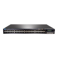
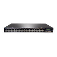
Juniper EX3200 Series Datasheet (8 pages)
Juniper Networks EX 3200 Series Fixed-Configuration Ethernet Switches
Brand:
Juniper
| Category:
Switch
| Size: 0.8 MB
Table of Contents
Features and Benefits
2
Product Options
3
Troubleshooting
6
Ordering Information
6
Warranty
6
About Juniper Networks
7
Juniper EX3200 Series Connecting (3 pages)
Connecting AC Power to an Switch
Brand:
Juniper
| Category:
Switch
| Size: 0.13 MB
Juniper EX3200 Series Installing (2 pages)
Installing a Fan Tray
Brand:
Juniper
| Category:
Switch
| Size: 0.15 MB
Juniper EX3200 Series Mounting (2 pages)
Brand:
Juniper
| Category:
Switch
| Size: 0.13 MB
Advertisement
Related Products
Juniper EX 3200 24T
Juniper EX 3200 48P
Juniper EX 3200 48T
Juniper EX3200-24T
Juniper EX3200-24P
Juniper EX3200-48T
Juniper EX3200-48P
Juniper EX3200-48T-DC
Juniper EX3200-24T-DC
Juniper EX 3200
Juniper Categories
Network Router
Switch
Gateway
Software
Network Hardware
More Juniper Manuals
Login
Sign In
OR
Sign in with Facebook
Sign in with Google
Upload manual
Upload from disk
Upload from URL