
Related Manuals for ECA CONFEO PREMIX P Series


Summary of Contents for ECA CONFEO PREMIX P Series
- Page 1 CONFEO PREMIX CONDENSING COMBI BOILER CONFEO PREMIX P 14/20/24/28/30/35 HM/HCH/HST OPERATING & INSTALLATION MANUAL...
-
Page 3: Table Of Contents
1 – INTRODUCTION....................... 5 2- GUARANTEE AND SERVICE..................5 3- DEFINITIONS OF SYMBOLS..................5 4- SAFETY RULES AND WARNINGS................. 6 4.1- Safety Instruc�ons..................... 6 4.2- Water Systems & Gas Supply Line................6 4.3- Installa�on......................... 6 4.4- Boiler Start Up......................6 4.5 - Usage and Maintenance................... - Page 4 10.1- Commissioning, Filling Water into Boiler and Heater Installa�on......26 10.2- Using the Device....................27 11- CONTROL PANEL....................27 11.1- Icons of Bu�ons..................... 27 11.2- LCD Screen......................29 11.3- Opera�on Func�ons....................30 12- ERROR CODES AND DESCRIPTIONS................ 31 13- USEFUL INFORMATION ON PRODUCT..............35 13.1- Informa�on on the Efficient Use of the Combi Boiler in Terms of Safety and Energy Consump�on........................
-
Page 5: Introduction
1- INTRODUCTION First of all, we would like to thank you for choosing E.C.A brand. E.C.A. Confeo Premix condensing boilers have been designed for an efficient, safe and comfortable central hea�ng and hot water requirement. The Confeo Premix condensing boilers can possibly use natural gas and LPG (G31-propane) according to the desired fuel preference. HM Model: It is designed for both Central Hea�ng (CH) and Domes�c Hot Water (DHW). -
Page 6: 4- Safety Rules And Warnings
4- SAFETY RULES AND WARNINGS 4.1- Safety Instruc�ons • When a gas leak is found or suspected; • Turn off the gas valve of the boiler and the valves of all other devices opera�ng with gas. • Shut off the stove, oven and similar appliances to put their flame out. •... -
Page 7: Usage And Maintenance
• Gas Type (Natural Gas or LPG), gas supply pressure (mbar), maximum DHW opera�ng water pressure (bar) and electricity supply voltage on the informa�on plate must be suitable with mains supply condi�ons. This is checked by qualified person. • A�er boiler start up, you should request informa�on about opera�ng the boiler and safety precau�ons from qualified person. -
Page 8: 5- Product
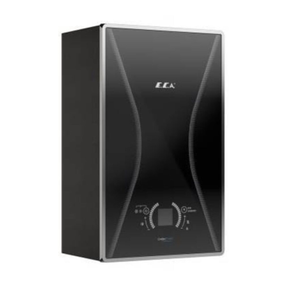
5- PRODUCT 5.1- General Specifica�ons Control panel is ergonomic and easy to use. The Confeo Premix condensing combi boiler with elegant glass touch panel and advanced LCD screen provides ease of use and service. On a LCD display with black instrument panel; you can see the opera�ng state icons, hea�ng and domes�c how water set temperature, water pressure level, failure codes and ac�oons to be taken. -
Page 9: Detailed View And List Of Components
5.3- Detailed View and List of Components 1- Main Exchanger 2- Silencer 3- Venturi 4- Fan 5.3- 5- Motorized Valve 6- Condensing WaterHose 7- Outlet Manifold 8- 3 Bar Safety Valve 9- Pressure Sensor 10- Siphon 11- Plated Heat Exchanger 12- Gas Valve 13- Return Manifold 14- Pump... - Page 10 5.3.1- HM Model CH Return DHW In DHW Supply CH Supply 5.3.2 - HCH Model CH Supply CH Return 5.3.3 - HST Model Storage Tank Outlet CH Return CH Supply STORAGE TANK Storage Tank Return...
-
Page 11: Technical Specifica�Ons
5.4 - Technical Specifica�ons CONFEO CONFEO CONFEO CONFEO CONFEO CONFEO Product type Unit PREMIX P 14 PREMIX P 20 PREMIX P 24 PREMIX P 28 PREMIX P 30 PREMIX P 35 HM-HCH-HST HM-HCH-HST HM-HCH-HST HM-HCH-HST HM-HCH-HST HM-HCH-HST Gas Category I2H, I3P, I2Esi, I2E(S), II2L3P, II2H3P, II2ELL3P, II2Esi3P Flue Types C13(X), C33(X), C43(X), C53(X), C63(X), C83(X), B23, B33 Gas Input Pressure (G20) - Page 12 Domes�c Hot Water (only valid for HM) Min. Domes�c flow for opera�ng L/min 2,5 (±%10) 2,5 (±%10) 2,5 (±%10) 2,5 (±%10) 2,5 (±%10) 2,5 (±%10) Min. Domes�c flow for closing L/min 2,0 (±%10) 2,0 (±%10) 2,0 (±%10) 2,0 (±%10) 2,0 (±%10) 2,0 (±%10) 10 ±%15 10 ±%15...
-
Page 13: Electrical Diagram
5.5- Electrical Diagram... -
Page 14: 6- Boiler Packaging
6- BOILER PACKAGING CAUTION: A�en�on must be paid to warning on packaging regarding handling and storage. •The device is delivered with a cartonboard with dimensions of 735 x 345 x 490 (HxWxD) mm, supported by upper and lower styrofoams. Moun�ng Bracket Figure 4 - Parts required for installa�on of the device (wall bracket, 5 gaskets for HM and HCH and 6 gaskets for HST water and gas connec�ons, 2 anchors and 2 fixing screws) are placed on the top styrofoam. -
Page 15: 7- Flues
1-90 Elbow 6- Flange Screws 2- Exhausted Gas Tap 7- Flange Gaskets 3- Air Inlet Tap 8- Flue Exhaust Terminal 4- Sealing Gasket ∅60 or ∅80 9- Inner Wall Connec�on Flange 5- Sealing Gasket ∅100 or ∅125 10- Outer Wall Connec�on Flange (EPDM) Table 3 7- FLUES 7.1- Flue Sizes... -
Page 16: Distances For Placement Of Flues
Figure 6 7.3- Distances for Placement of Flues Figure 7... -
Page 17: 8- Installation
POSITION DISTANCE(cm) POSITION DISTANCE (cm) A- Below a window G- Next to ver�cal or horizontal pipe B - Below an air vent H- Below the distance grille from the outside of the building C- Below rain channel I- Distance from the inner corner of the building D- Under the balcony L- From the ground or from the... -
Page 18: Independent Opera�On From Ambient Air (Type C)
•Do not install your boilers in locations that will be exposed to direct sunlight. Sunlight can cause color change on the exterior of your device over time. Ambient temperature of device's installation location should be between 5-35°C. • The device can be used at altitudes up to 2000 m above sea level. •There is no need to remove side panels in the combi boiler service opera- tions. -
Page 19: Moun�Ng The Boiler
8.3- Mounting the Boiler After determination of boiler mounting location follow the instructions given below. • The points of lock screws of wall bracket and assembly bracket are marked by using the assembly template inside installation and user’s operating instructions of the device (pages 34-35-36). •... -
Page 20: Gas And Water Connec�Ons
Figure 10 9.2- Gas and Water Connections Water and gas supply connections between the boiler and the mounting bracket can be fixed with the pipes and the nipples. 9.2.1- HM Model a) CH flow ¾ ‘’ (hot) b) DHW outlet ½ ‘’ (hot) c) Gas inlet ¾’’... - Page 21 9.2.2- HCH Model a) CH flow ¾ ‘’ (hot) b) Water filling line1/2" c) Gas inlet ¾’’ d) CH return ¾’’ (cold) 9.2.3- HST Model a) CH flow ¾ ‘’ (hot) b) Boiler supply water (hot) c) Gas inlet ¾’’ d) Boiler return (cold) e) Water Filling Line ½...
-
Page 22: Electrical Connec�On
9.3- Electrical Connection Electrical installation must be made according to the national and local instructions. The boiler must be earthed and a standard 230 V AC – 50 Hz supply is required. CAUTION: Disconnect power supply to prevent electrical shock before connecting the electrical supply. -
Page 23: Room Thermostat
9.4- Room Thermostat Optional room thermostats compatible with your device can be used to control heating system. E.C.A. On/Off Room Thermostat E.C.A. Smart Room Thermostat E.C.A. Smart Room T6360 Boiler-Air Condi�oning Thermostat 7006901312 7006907804 7006907531 E.C.A. Digital Room Thermostat Wireless, E.C.A. -
Page 24: Outdoor Temperature Sensor
9.5- Outdoor Temperature Sensor To connect the room thermostat or outdoor sensor to the device, the connections behind the control panel are used. For the room thermostat, the bridged cable connection on the back of the control panel is removed and the outer air sensor is connected to free sockets on the terminal. •... -
Page 25: Room Thermostat And Outdoor Temperature Sensor Connec�On
9.6- Room Thermostat and Outdoor Temperature Sensor Connec�on DETAIL A MAINBOARD MAINBOARD DETAIL B Storage tank connec�on cables are connected to the indicated terminal points. Outdoor Timers To make the To make the Solar Sensor is cable are Opentherm On/Off Room system installed by connected... -
Page 26: 10- Commissioning, Use And Turning Off The Boiler
In your combi only E.C.A. Room thermostats approved by authorized services should be used. Otherwise, it may cause your device to malfunction. In such cases, no liability is accepted.. The connections of room thermostat, outdoor sensor and timer must be performed certainly by qualified person. -
Page 27: Using The Device
ATTENTION: In order to prevent calcification of the heat exchanger, you are advised not to use hard water, natural spring water instead of mains water. - Check the domestic water installation by opening the hot water tap. Check for any leaks in the piping. - The exhaust gas flue assembly must be installed from the original parts in accordance with the instruc- tions. - Page 28 1 Nu. Button: Reset Button Main Functions : • Exit from lockout error (EXX) • ECO mode activation • Comfort mode activation When your device fails, the error code will start flashing on the display. There are 2 types of errors, lockout (EXX) and blocking (FXX) error.
-
Page 29: Lcd Screen
11.2- LCD Screen LCD screen display icons described here below. OPENTHERM ROOM THERMOSTAT CONNECTION ON/OFF DOMESTİC HOT CENTRAL HEATING WATER ICON ICON ECO/COMFORT MODE SOLAR PANEL MODE TEMPERATURE 70-100 % Modula�on VALUE 35-70 % Modula�on 0-35 % Modula�on FLAME MODULATION ICON PRESSURE INDICATOR 11.2.1- Flame Icon... -
Page 30: Opera�On Func�Ons
11.3- Operation Functions 11.3.1- Standby (OFF Mode) It is the mode in which the device can be placed in standby. When this mode is taken, central heating and domestic water heating demands are not made. To switch to OFF mode, it is necessary to hold the button "6"... -
Page 31: 12- Error Codes And Descriptions
11.3.6- ECO Mode By pressing the "Reset" button, Eco-Comfort modes can be switched. When Eco mode is active, "Eco" icon is displayed on the LCD screen. Eco mode is only for radiator heating circuit. It has no effect on use of domestic water circuit. - Page 32 No temperature is detected by 1- Press reset bu�on. Error on Temperature Sensor temperature sensor for supply 2- If the error is s�ll present (or persists) a�er for Supply Water water. reset, no�fy authorized service of E.C.A. No temperature is detected by 1- Press reset bu�on.
- Page 33 1- Press reset bu�on. Fan Feedback Fault Failure of fan or fan cable 2- If the error is s�ll present (or persists) a�er reset, no�fy authorized service of E.C.A. It occurs when the temperature of Over Temperature Error for 1- No�fy authorized service of E.C.A. Flue Gas the flue gas exceeds 95 Insufficient water circula�on...
- Page 34 1-Switch off and on the boiler. Modula�on Room Thermostat Room Thermostat may be failed or 2- Press reset bu�on. Comunica�on Fault connec�on problem 3- If the error is s�ll present (or persists) a�er reset, no�fy authorized service of E.C.A. 1- Press reset bu�on. Storage tank sensor might be Storage Tank Sensor Fault 2- If the error is s�ll present (or persists) a�er...
-
Page 35: 13- Useful Information On Product
13- USEFUL INFORMATION ON PRODUCT 13.1- Information on the Efficient Use of the Combi Boiler in Terms of Safety and Energy Consumption Isolation of your building is extremely important. Energy saving is achieved at a considerable degree since the heat loss is lowest in houses with double-glazed windows and insulated walls. •... -
Page 36: 14- Annexes
14- ANNEXES 14.1- Characteristic Curve Of Water Pressure Height Of The Pump (Pump Headflow Rate) 15-60 (14-20-24-28-30 KW) Flow rate- Height of the pump curve 7,00 6,00 5,00 4,00 3,00 2,00 1,00 0,00 0,00 0,50 1,00 1,50 2,00 2,50 Q [m3/h] 15-70 (35 kW) Flow rate- Height of the pump curve 8,00... -
Page 37: 15- Installation Template
15- INSTALLATION TEMPLATE 15.1- HM Model... -
Page 38: Hch Model
15.2- HCH Model... -
Page 39: Hst Model
15.3- HST Model... -
Page 40: 16- Product Fiches And Package Label Calculations
16- PRODUCT FICHES AND PACKAGE LABEL CALCULATIONS 16.1- PRODUCT FICHES Product fiche for combination boilers as required by EU regulations No811/2013 Confeo Premix P Combi ERP Units HCH-HST MODEL Supplier's name or E.C.A. trademark Confeo Confeo Confeo Confeo Confeo Confeo Supplier's model identifier Premix P Premix P... - Page 41 Confeo Premix P Combi ERP HM MODEL Units Supplier's name or trademark E.C.A. Confeo Confeo Confeo Confeo Confeo Confeo Supplier's model identifier Premix P Premix P Premix P Premix P Premix P Premix P 14 kW 20 kW 24 kW 28 kW 30 kW 35 kW...
- Page 47 PRODUCTION Organize Sanayi Bolgesi 3.Kisim Mustafa Kemal Bulvari No:13 45030 MANISA Tel.:+90 236 213 00 21 Fax:+90 236 213 08 59 email:emas@emas.com.tr www.emas.com.tr...