Table of Contents
Advertisement
Jan.2004
TABLE OF CONTENTS
SPECIFICATIONS.............................................................2
LOCATION OF CONTROLS ..........................................3
LOCATION OF CONTROLS PARTS LIST ...................5
EXPLODED VIEW 1 .........................................................6
EXPLODED VIEW 2 .........................................................7
EXPLODED VIEW 3 .........................................................8
EXPLODED VIEW 4 .........................................................9
EXPLODED VIEW PARTS LIST ...................................10
PARTS LIST......................................................................11
CHECKING THE VERSION NUMBER.......................17
USERS DATA SAVE AND LOAD................................17
TEST MODE.....................................................................21
RESTORING THE FACTORY SETTINGS...................24
SYSTEM SOFTWARE UPDATE PROCEDURE .........26
BLOCK DIAGRAM.........................................................28
Copyright © 2004 ROLAND CORPORATION
All rights reserved. No part of this publication may be reproduced in any form without the written permission
of ROLAND CORPORATION.
CIRCUIT BOARD (MAIN BOARD) .............................30
(MAIN BOARD DIGITAL IO).......................................34
CIRCUIT DIAGRAM (MAIN BOARD DSP)...............38
CIRCUIT DIAGRAM (MAIN BOARD POWER)........40
CIRCUIT BOARD (SWITCH SHEET) ..........................42
CIRCUIT DIAGRAM (GAIN BOARD) ........................44
CIRCUIT DIAGRAM (GUITAR BOARD) ...................45
CIRCUIT DIAGRAM (5V POWER BOARD) ..............45
CIRCUIT DIAGRAM (PHONES BOARD) ..................46
CIRCUIT DIAGRAM (SW BOARD).............................48
CIRCUIT DIAGRAM (XLR JACK BOARD) ................50
ERROR MESSAGES ........................................................51
17058222E0
SERVICE NOTES
Issued by RJA
Printed in Japan (0800) (NB)
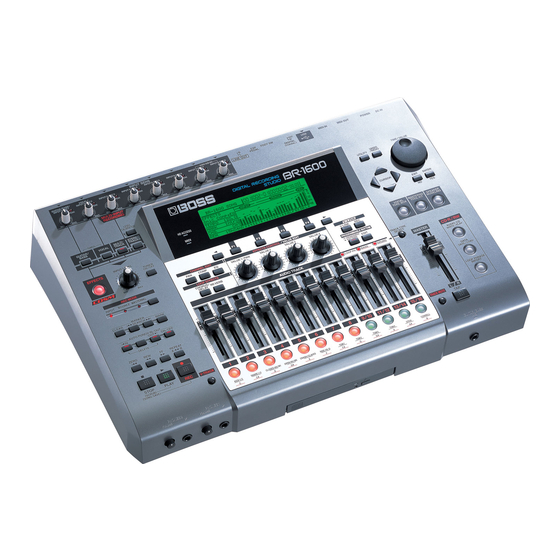
BR-1600CD
Advertisement
Table of Contents

Related Manuals for Roland BOSS BR-1600CD


Summary of Contents for Roland BOSS BR-1600CD
-
Page 1: Table Of Contents
SYSTEM SOFTWARE UPDATE PROCEDURE ..26 CIRCUIT DIAGRAM (XLR JACK BOARD) ....50 BLOCK DIAGRAM............28 ERROR MESSAGES ............51 Copyright © 2004 ROLAND CORPORATION All rights reserved. No part of this publication may be reproduced in any form without the written permission of ROLAND CORPORATION. 17058222E0... -
Page 2: Specifications
24 bit, ∆∑ Modulation (VOCAL) Power Supply 24 bit, ∆∑ Modulation (MULTI-TRACK) 24 bit, ∆∑ Modulation (STEREO TRACKS) DC 12 V; Supply AC Adaptor (Roland PSB-3U) DA Conversion: 24 bit, ∆∑ Modulation Power Consumption Internal Processing:24 bit (digital mixer section) -
Page 3: Location Of Controls
BR-1600CD LOCATION OF CONTROLS fig.panel1... - Page 4 Jan.2004 fig.panel2...
-
Page 5: Location Of Controls Parts List
BR-1600CD LOCATION OF CONTROLS PARTS LIST [PARTS] PART CODE CATEGORY NAME PART NAME DESCRIPTION Q'TY 03343501 CASING TOP CASE 01891801 KNOB,BUTTON U R-KNOB S1 LCG BLK 03459212 POTENTIOMETER 9M/M ROTARY POTENTIOMETER EVUF2KFK315D 100KRD 02679456 DIODE LED (RED) SLR-342VR3F 00900145 KNOB,BUTTON D S-KEYTOP SD1H BLK 01904112... -
Page 6: Exploded View 1
Jan.2004 EXPLODED VIEW 1 ffig.explo-2 40122490 DOUBLE FACED TAPE #500 W5MM 20M * Exerise care to avoid becoming defromed. whe you exchange this panel sheet. -
Page 7: Exploded View 2
BR-1600CD EXPLODED VIEW 2 ffig.explo-2 32 33... -
Page 8: Exploded View 3
Jan.2004 EXPLODED VIEW 3 fig.explo-1... -
Page 9: Exploded View 4
BR-1600CD EXPLODED VIEW 4 fig.explo-1... -
Page 10: Exploded View Parts List
Jan.2004 EXPLODED VIEW PARTS LIST [PARTS] PART CODE CATEGORY NAME PART NAME DESCRIPTION Q'TY 03343501 CASING TOP CASE 03343512 CHASSIS CHASSIS 03345956 CHASSIS LCD HOLDER 03343434 DISPLAY UNIT F-51405GNY-LY-AB 01783945 KNOB,BUTTON N S-KEYTOP MD3H 01783923 KNOB,BUTTON N S-KEYTOP MD1H 02013090 KNOB,BUTTON F C-KEYTOP MX1H CLR... -
Page 11: Parts List
BR-1600CD PARTS LIST fig.part1e CONSIDERATION ON PARTS ORDRING SAFETY PRECAUTIONS: When ordering any parts listed in the parts list, please specify the following items in the order sheet. The parts marked have PART NUMBER DESCRIPTION MODEL NUMBER safety-related characteristics. Use 22575241 Sharp Key C-20/50... - Page 12 Jan.2004 DISK DRIVE UNIT 03459634 2F040L0 NOTE: Replacement 2F040L0 should be made on a unit base. PCB ASSY 72450690 MAIN BOARD ASSY NOTE: ‘MAIN BOARD ASSY’ includes the following parts. 03564401 WIRING GND CABLE A (LONG) on MAIN 03564412 WIRING GND CABLE B (SHORT) on MAIN 03563945...
- Page 13 BR-1600CD 02563534 ICS512MT IC (PLL) IC44 on MAIN 03120356 AK4114VQ IC (DIGITALAUDIO TRANSCEIVER) IC51 on MAIN 02903745 S-80930CNMC-G80 IC (RESET) IC83,IC15 on MAIN 15289124 PC-4007 IC (PHOTO COUPLER) IC4 on MAIN 15189147N0 UPC4072C IC (OP AMP) IC8 on GUITAR 02346123 NJM4556AD IC (OP AMP) IC6,IC7 on PHONES...
- Page 14 Jan.2004 RESISTOR 00567267 RPC05T 682 J MTL.FILM RESISTOR on MAIN 00567245 RPC05T 472 J MTL.FILM RESISTOR on MAIN 00566967 RPC05T 470 J MTL.FILM RESISTOR on MAIN 00566867 RPC05T 100 J MTL.FILM RESISTOR on MAIN 15399989 MCR50JZH680 1/2W CHIP RESISTOR R373 on MAIN 00567134 RPC05T 681 J MTL.FILM RESISTOR...
- Page 15 BR-1600CD CAPACITOR 03564389 ECJ1VB1E563K CERAMIC CAPACITOR on MAIN 01674612 ECJ1VB1H103K CERAMIC CAPACITOR on MAIN 01674467 ECUV1H102JCV CERAMIC CAPACITOR on MAIN 01120301 ECEV1CA221P 220UF CHEMICAL CAPASITOR C364,C532,C533,C541 on MAIN 02897045 ECEV1CA220WR CHEMICAL CAPACITOR C310,C314,C369,C374,C416,C421 on MAIN 02897056 ECEV1CA471UP CHEMICAL CAPACITOR C538,C486,C508,C524,C534,C537, on MAIN 15369262 ECEV1HA010SR CHEMICAL CAPACITOR...
- Page 16 Jan.2004 CONNECTOR 02010878 18FE-ST-VK-N FOR WIRING CONNECTOR CN3 on SW 02016956 22FE-ST-VK-N CONNECTOR CN2 on SW 02122467 24FE-ST-VK-N CONNECTOR CN1 on SW, CN6 on GAIN 13429293 51048-0400 (4P) CABLE HOLDER CN4 on GUITAR 02010867 16FE-ST-VK-N CONNECTOR CN8 on PHONES, CN7 on GAIN 02782645 24 5600 050 100 883 CONNECTOR...
-
Page 17: Checking The Version Number
BR-1600CD CHECKING THE VERSION Backing up a song (Song Backup) NUMBER Insert an empty CD-R/RW disc into the BR-1600CD’s CD-R/RW drive. The drive’s access indicator will begin to flash. Wait until this indicator stops flashing and turns off before proceeding. With the unit in normal operating mode, simultaneously press the [Left] and [Right] page scroll buttons. - Page 18 Jan.2004 Move the cursor to the type of data you want to back up and press [F1] (SELECT). The data will selected for backup. • The range of available write speeds can sometimes be limited by the type fig.41-07ad of disc being used. In such cases, the BR-1600CD will allow you to select only the supported speeds using the TIME/VALUE dial.
- Page 19 BR-1600CD Press [ENTER/YES]. Use the TIME/VALUE dial to set the write speed. If you want to cancel the backup, press [EXIT/NO]. Write Speed: The message “Write Sure?” will appear. x2 (352 Kbps)Writes twice as fast. fig.41-09d x4 (704 Kbps)Writes four times as fast. x8 (1408 Kbps)Writes eight times as fast.
- Page 20 Jan.2004 Reading backup songs back into Reading backup user data back the hard disk (Song Recover) into the hard disk (User Recover) Insert a CD-R/RW disc containing backup songs into the BR-1600CD’s Insert a CD-R/RW disc containing backup user data into the BR- CD-R/RW drive.
-
Page 21: Test Mode
BR-1600CD fig.41-21d_recoveruserlphall.bmp Press [ENTER/YES]. The hard disk will be initialized and then the recovery process will begin. When the message “Complete!” appears, it indicates that the recovery has been completed successfully. If you select “LOOP PHRASE A–H,” a recovery destination will appear at the bottom of the display. - Page 22 Jan.2004 Switch Test Categories MARKER MARK MARKER SEARCH >> -> REC MODE MASTERING LED GOES OFF You may use the following operations to switch test categories. MARKER SEARCH << -> REC MODE BOUNCE LED GOES OFF Press the [STOP] and [ ] switches simultaneously to return to the MARKER CLEAR ->...
- Page 23 BR-1600CD 7. MIDI 2-2 Confirm that the TRACK LEDs (red) light up. • Confirm that all TRACK LEDs 1 to 15/16 light up red. Test the MIDI transmission. “ ALL Tracks LED s : RED “ “ -- “ appears in the display. The test is passed if the red LEDs for all tracks are lit.
-
Page 24: Restoring The Factory Settings
Jan.2004 11. AF-AD 14. USB Confirm operation of the AF-AD. • Use a USB cable to connect the unit’s USB connector to a computer’s USB port. • Set up the same connections as in Step 10 (GUITAR). • Transmission is checked automatically; confirm that “OK” appears in the •... - Page 25 BR-1600CD MIXER icon fig.53-28 fig.53-33d 2, 3 When this icon is selected, 2, 3, • Track Compressor, EQ, Pan 4, 5 • Loop Effects • Input Select • Level Calibration • Recording Mode will be returned to the values they normally have immediately after Song New is performed.
-
Page 26: System Software Update Procedure
Jan.2004 Precautions for initialization • Press [EXIT/NO] if you want to cancel an initialization process. • In certain cases, the message “Save Current?” will appear during the initialization procedure, and this indicates that the current song contains audio that has been newly recorded or edited, or modified parameters that have not yet been saved. - Page 27 BR-1600CD...
-
Page 28: Block Diagram
Jan.2004 BR-1600CD BLOCK DIAGRAM fig.block GUITAR BOARD XLR JACK BOARD 5V POWER JK11 JK12 JK13 JK14 JK15 JK16 JK17 JK18 JK19 BOARD INPUT1(Hi-Z) INPUT1 INPUT2 INPUT3 INPUT4 INPUT5 INPUT6 INPUT7 INPUT8 (#02900412) D+5V +12V WIRING MAIN BOARD HDD POWER CN11 CN12 CN101 (#02789367) -
Page 29: Circuit Board (Main Board)
Jan.2004 BR-1600CD CIRCUIT BOARD (MAIN BOARD) mbal.tif mtal.tif... -
Page 30: Circuit Diagram (Main Board Analog)
Jan.2004 BR-1600CD CIRCUIT DIAGRAM (MAIN BOARD ANALOG) fig.manaa H:GUITAR ,L:MIC CN11 H*GUITAR from GUITAR guitar input BOARD CN4 R712 R713 4.7k 52147-0410 TP990 DTA114EUA R698 100k to XLR DTC114EUA R699 JACK 100k BOARD TP991 R700 C740 R701 C741 R702 C742 R703 C743 0.056... -
Page 31: Circuit Diagram (Main Board Digital Io)
Jan.2004 BR-1600CD CIRCUIT DIAGRAM (MAIN BOARD DIGITAL IO) fig.mdia 256fs select C236 VCC_5V IC39 TC7WH157FU TP245 VCC_5V R155 3.3V->5V level DIN256FS 256FS shift EXCML20A390U TP249 CLK_SEL IC41 IC40 C237 TC7SET04FU TP246 TA78M05F VCC_5V L:A ch/H:B ch CPU / DIN CPU_FS C238 C239 C240... -
Page 32: Circuit Diagram (Main Board Digital)
Jan.2004 BR-1600CD CIRCUIT DIAGRAM (MAIN BOARD DIGITAL) fig.mdiga D 3. 3 A[0:19],A[21:23] A[0:19],A[21:23] IDE_RESET# RESET# D[0:15] D[0:15] TP512 TP513 IC1B IC1A 12 V TO HDD #CS2 N1608Z601 #CS4 POWER 32M FLASH HD power D 3. 3 N1608Z601 TC74VHC04FT TC74VHC04FT IC2A DD10 UDQM DD10... -
Page 33: Circuit Diagram (Main Board Dsp)
Jan.2004 BR-1600CD CIRCUIT DIAGRAM (MAIN BOARD DSP) fig.mdspa ch select signal decode C171 0.1 D 3. 3 IC27A TC74VHC04FT IC27B IC26A TC74VHC04FT TC74VHC21FT ESP TRS/TRR ch select signal section D 3. 3 SEL DSP SYNC LOAD IC27C TC74VHC04FT ESP#1_TRCK TRS/TRR IC25 TC74VHC161FT 0ch-17ch... -
Page 34: Circuit Diagram (Main Board Power)
Jan.2004 BR-1600CD CIRCUIT DIAGRAM (MAIN BOARD POWER) fig.mpowa Q31A HD power TP878 TPC8303 hard disk power & LCD back TP879 R426 light C524 C525 supply(12V) 100k 470/16 DTC114EUA CPU power supply(3.3V):regulator digital power supply(3.3V):DC-DC convertor digital power digital power supply(5V):DC-DC convertor CN18 supply(5V) B7B-PH-K-S... -
Page 35: Circuit Board (Switch Sheet)
Jan.2004 BR-1600CD CIRCUIT BOARD (SWITCH SHEET) fig.sbp... -
Page 36: Circuit Diagram (Gain Board)
Jan.2004 CIRCUIT DIAGRAM (GAIN BOARD) fig.sgaia GUITAR/BASS/ MIC1 VOCAL/MIC2 MIC3 MIC4 MIC5 MIC6 MIC7 MIC8 GUITAR/BASS/ MIC1 VOCAL/MIC2 MIC3 MIC4 MIC5 MIC6 MIC7 MIC8... -
Page 37: Circuit Diagram (Guitar Board)
BR-1600CD CIRCUIT DIAGRAM (GUITAR BOARD) fig.sguia GUITAR BOARD C103 C104 NIU(10/16) INPUT1(Hi-Z) to MAIN C105 1SS133 R132 0 C134 NIU(BL02RN2-R62) R133 0.1(lead type) BOARD JK11 CN11 10/16 IC8A C106 R134 UPC4072C 51048-0400 100p HLJ4306-01-3080 R135 IC8B IC8C NIU(BL02RN2-R62) UPC4072C UPC4072C C107 R136 C108... -
Page 38: Circuit Diagram (Phones Board)
Jan.2004 BR-1600CD CIRCUIT DIAGRAM (PHONES BOARD) fig.sphoa to MAIN BOARD CN14 100/16 A-GND HEADPHONE1_L R100 2.2k R137 15k A-GND HEADPHONE1_R A-GND OUTPUT MUTE A-GND VR28A VR28B R138 R429 R103 A-GND EVJC25 50kA L15 EVJC25 50kA L15 100/16 NIU(BL02RN2-R62) 10/16 R104 2SC2878A A-GND R105... -
Page 39: Circuit Diagram (Sw Board)
Jan.2004 BR-1600CD CIRCUIT DIAGRAM (SW BOARD) fig.sswa (for EMC) frame GND frame GND EN1B EVE_GC1_F20_24B EN1A EVE_GC1_F20_24B EVUF2K 50kB EVUF2K 50kB EVUF2K 50kB A 3. 3 EVUF2K 50kB EVUF2K 50kB A 3. 3 100/16 VR7A VR9A VR11A VR13A VR15A VR17A BL02RN2R1N1A EWAP1@50kB EWAP1@50kB... -
Page 40: Circuit Diagram (Xlr Jack Board)
Jan.2004 CIRCUIT DIAGRAM (XLR JACK BOARD) fig.sxlra JK19 JK18 JK17 JK16 NC3FAH( or JY-5033A) NC3FAH( or JY-5033A) NC3FAH( or JY-5033A) NC3FAH( or JY-5033A) INPUT8 INPUT7 INPUT6 INPUT5 CN12 18FE-BT-VK-N JK15 JK14 JK13 JK12 NC3FAH( or JY-5033A) NC3FAH( or JY-5033A) NC3FAH( or JY-5033A) NC3FAH( or JY-5033A) INPUT4 INPUT3... -
Page 41: Error Messages
BR-1600CD ERROR MESSAGES Disc Not Ready! Cause: There is no CD-R/RW disc in the drive. Action: Place a CD-R/RW disc in the drive. Blank Disc! Drive Busy! Cause: Disc in the CD-R/RW drive contains no data. Action: Load a CD-R/RW disc that has data written on it. Cause: The data on the hard disk has become fragmented, causing delays in reading and writing data. - Page 42 Jan.2004 Medium Error! Set Location! Cause: There is a problem with the CD-R/RW disc or hard disk. Cause: No target data or file has been selected yet. Alternatively, the disc on the CD-R/RW drive is unreadable. Action: Select the data before continuing. Action 1: Confirm that the correct type of disc is placed in the CD-R/RW drive.