Siemens 1FK7 Series Operating Instructions Manual
Synchronous motor
Hide thumbs
Also See for 1FK7 Series:
- Configuration manual (252 pages) ,
- Instructions manual (156 pages)
Table of Contents
Advertisement
Advertisement
Table of Contents

Related Manuals for Siemens 1FK7 Series


Summary of Contents for Siemens 1FK7 Series
- Page 1 Synchronous motors 1FK7 Operating instructions · 03/2011...
- Page 3 ___________________ Synchronous Motors 1FK7 Introduction ___________________ Safety instructions ___________________ Description ___________________ Preparing for use ___________________ Synchronous Motors 1FK7 Installation ___________________ Connecting Operating Instructions ___________________ Commissioning ___________________ Operation ___________________ Maintenance Decommissioning and ___________________ disposal ___________________ Appendix 03/2011 610.40700.40c...
- Page 4 Note the following: WARNING Siemens products may only be used for the applications described in the catalog and in the relevant technical documentation. If products and components from other manufacturers are used, these must be recommended or approved by Siemens. Proper transport, storage, installation, assembly, commissioning, operation and maintenance are required to ensure that the products operate safely and without any problems.
-
Page 5: Table Of Contents
Table of contents Introduction..............................5 About these operating instructions ....................5 Safety instructions ............................. 7 General safety notes........................7 Safety and application instructions ....................8 Description............................... 11 Product description ........................11 Technical features........................12 Rating plate (type plate).......................14 Design ............................15 3.4.1 Standards and regulations ......................15 3.4.2 Types of construction........................15 3.4.3... - Page 6 Table of contents Commissioning ............................37 Measures prior to commissioning ....................37 Switching on..........................39 Operation..............................41 Safety guidelines in operation..................... 41 Faults............................42 Non-operational periods......................44 Maintenance ............................45 Inspection and maintenance ....................... 45 9.1.1 Safety instructions........................45 9.1.2 Maintenance intervals .........................
-
Page 7: Introduction
These operating instructions are valid in conjunction with the relevant SIEMENS Configuration Manual. Siemens continually strives to improve the quality of information provided in these operating instructions. If you find any mistakes or would like to offer suggestions about how this document could be improved, please contact the Siemens Service Center. - Page 8 Introduction 1.1 About these operating instructions Synchronous Motors 1FK7 Operating Instructions, 03/2011, 610.40700.40c...
-
Page 9: Safety Instructions
(see rating plate), or arrange for any maintenance work to be carried out by the SIEMENS Service Center. Systems and machines with converter-fed low-voltage three-phase motors must fulfill the protective requirements of the EMC Directive. -
Page 10: Safety And Application Instructions
Note Siemens Service Center For any service work you may require, you are advised to contact your nearest Siemens Service Center to request their services and support for maintenance activities. Synchronous Motors 1FK7 Operating Instructions, 03/2011, 610.40700.40c... - Page 11 Safety instructions 2.2 Safety and application instructions Observing the five safety rules For your personal safety and to prevent material damage when working on the machine, always observe the safety instructions and the following five safety rules. Apply the five safety rules in the order stated before starting work at the machine.
- Page 12 Safety instructions 2.2 Safety and application instructions Notes about electromagnetic fields WARNING Electromagnetic fields Electromagnetic fields are generated by the operation of electrical power equipment – such as transformers, converters or motors. Electromagnetic fields can destroy electronic devices, which could cause them to malfunction.
-
Page 13: Description
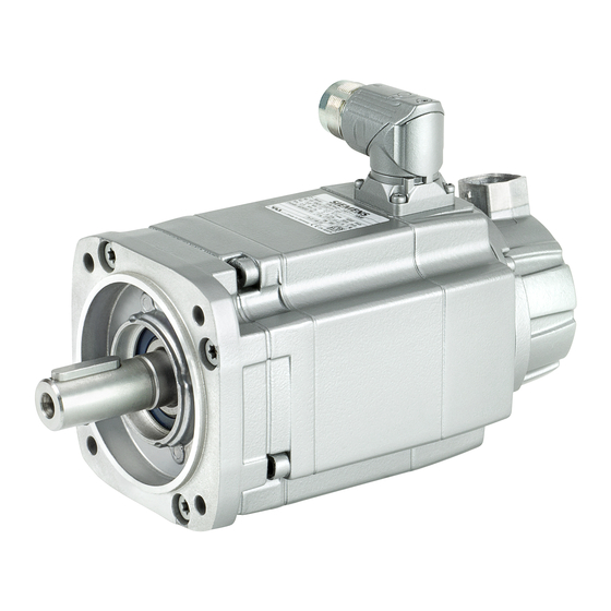
Description Product description Overview 1FK7 motors are compact permanent-magnet synchronous motors. The available options, gear units and encoders, together with the expanded product range, mean that the 1FK7 motors can be optimally adapted to any application. They therefore also satisfy the permanently increasing demands of state-of-the-art machine generations. -
Page 14: Technical Features
Description 3.2 Technical features Technical features Table 3- 1 Technical features Type of motor Permanent-magnet synchronous motor Magnet material Rare-earth magnetic material Cooling Natural cooling Insulation of the stator winding according to EN Temperature class 155 (F) for a winding temperature of 60034-1 (IEC 60034-1) ΔT = 100 K at an ambient temperature of +40°... - Page 15 Description 3.2 Technical features Integrated encoder systems for motors with DRIVE- AS24DQI absolute encoder single-turn 24 bit , for SH 36 to CLiQ interface SH 100 AM24DQI absolute encoder 24 bit + 12 bit multiturn, for SH 36 to SH 100 AS20DQI absolute encoder single-turn 20 bit, for SH 36 to ...
-
Page 16: Rating Plate (Type Plate)
Induced voltage at rated speed U Temperature class Motor version Standards and specifications 2D code Degree of protection Motor weight m [kg] Rated speed n [rpm] Maximum speed n [rpm] SIEMENS motor type/order number Synchronous Motors 1FK7 Operating Instructions, 03/2011, 610.40700.40c... -
Page 17: Design
Description 3.4 Design Design 3.4.1 Standards and regulations The motors comply with the following regulations according to IEC / EN 60034: Table 3- 3 Regulations that have been applied Feature Standard Ratings and operating performance IEC/EN 60034-1 Degree of protection IEC/EN 60034-5 Type of construction IEC/EN 60034-7... -
Page 18: Ambient Conditions
Description 3.4 Design 3.4.4 Ambient conditions The following temperature ranges apply to naturally-cooled motors. ● Permissible temperature range in operation: T = -15 °C to +40 °C ● Permissible temperature range during storage: T = -20 °C to +70 °C For deviating conditions (ambient temperature >... -
Page 19: Noise Emission
Description 3.4 Design 3.4.6 Noise emission When operated in the speed range 0 to rated speed, 1FK7 motors can reach the following measuring-surface sound pressure level Lp(A): Table 3- 5 Sound pressure level Shaft height Measuring-surface sound pressure level Lp(A) 1FK701 to 1FK704 55 dB(A) + 3 dB tolerance 1FK706... - Page 20 Description 3.4 Design Synchronous Motors 1FK7 Operating Instructions, 03/2011, 610.40700.40c...
-
Page 21: Preparing For Use
The drive systems are assembled on an individual basis. Upon receipt of the delivery, check immediately whether the items delivered are in accordance with the accompanying documents. Siemens will not accept any guarantee for claims relating to defects which are submitted at a later date. - Page 22 Preparing for use 4.2 Transport and storage WARNING Transporting and lifting the motor using its eyebolts In the case of larger motors, eyebolts are attached to the bearing end shields or threads to attach eyebolts. Eyebolts must be screwed in completely and secured by hand (approx. 8 Nm); do not overtighten.
-
Page 23: Storage
Preparing for use 4.2 Transport and storage 4.2.2 Storage The motors can be stored for up to two years in a dry, dust-free room that is not susceptible to vibration (v < 0.2 mm/s) without the specified storage time being reduced. CAUTION Seizure damage to bearings If the motors are stored incorrectly, bearing seizure damage can occur (e.g. - Page 24 Preparing for use 4.2 Transport and storage Synchronous Motors 1FK7 Operating Instructions, 03/2011, 610.40700.40c...
-
Page 25: Installation
Installation Installation CAUTION Temperature-sensitive parts Some parts of the electrical motor enclosure can reach temperatures that exceed 100 °C. Temperature-sensitive components, e.g. cables, etc., can be damaged if they come into direct contact with the motor enclosure. When arranging temperature-sensitive components, ensure that they do not come into contact with the motor enclosure. - Page 26 Installation 5.1 Installation ● Eyebolts that have been screwed in must either be tightened or removed after installation. ● Ensure that the flange joint sits evenly; avoid applying an excessive force to fixing screws when tightening. Use hexagon socket head cap screws with a property class of 8.8. Observe the tightening torques for the fixing screws of the motor flange.
-
Page 27: Attaching Transmission Elements
Installation 5.2 Attaching transmission elements Attaching transmission elements NOTICE Do not subject the motor's shaft and bearings to impact. Do not exceed the permissible axial and radial forces at the shaft extension, as defined in the configuration specifications. Axial forces are not permitted for motors with an integrated holding brake. Suitable equipment (see figure) must be used when fitting and removing transmission elements (e.g. -
Page 28: Vibration Response
Installation 5.3 Vibration response Vibration response Motors with a keyway are balanced with a half fitted key by the manufacturer. The vibration response of the system at the installation location is influenced by transmission elements, any mounted parts, the alignment, the installation, and external vibrations. As a result, the motor's vibration values may change. -
Page 29: Connecting
Connecting Electrical connection 6.1.1 Safety instructions DANGER Risk of electric shock When the rotor is turning, a voltage of approx. 300 V is available at the motor terminals. All work performed on electrical components must be carried out when the motor is at a standstill. -
Page 30: Circuit Diagram
Encoder systems and temperature sensors are electrostatic sensitive devices (ESD). Do not touch the connections with either hands or tools that could be electrostatically charged! ● We recommend that SIEMENS prefabricated cables are used (not included in the scope of delivery). These cables reduce installation costs and increase operational reliability (see the Configuration Manual). - Page 31 Connecting 6.1 Electrical connection ● Take measures to ensure that connecting cables cannot rotate, are not subject to strain and pushing force and also provide anti-kink protection. It is not permissible to subject the connector to continuous force. ● The coding groove of the plug-in connection must be inserted so that it is aligned in the socket connector and the screw cap must be tightened by hand as far as it will go.
- Page 32 Connecting 6.1 Electrical connection Current-carrying capacity for power and signal cables The current carrying capacity of PVC/PUR-insulated copper cables is specified for routing types B1, B2, C and E under continuous operating conditions in the table with reference to an ambient air temperature of 40 °C. For other ambient temperatures, the values must be corrected by the factors from the "Derating factors"...
- Page 33 Connecting 6.1 Electrical connection Table 6- 2 Derating factors for power and signal cables Ambient air temperature [°C] Derating factor according to EN 60204-1, Table D1 1.15 1.08 1.00 0.91 0.82 0.71 0.58 Connector types Figure 6-2 Power connector 1FK702. - 1FK710. size 1 Resolver Incremental Encoder sin/cos 1 Vpp Absolute Encoder...
-
Page 34: Rotating The Connector For 1Fk7Xxx5 And 1Fk7Xxx-7
Connecting 6.1 Electrical connection 6.1.4 Rotating the connector for 1FK7xxx5 and 1FK7xxx-7 Power connectors and signal connectors can be rotated to a limited extent. A suitable socket connector can be used to rotate the angle plug. Make sure that the socket connector is completely secure to avoid damaging the pin contacts. -
Page 35: Rotating The Connector For 1Fk7Xxx-2, 1Fk7Xxx-3, 1Fk7Xxx-4
Connecting 6.1 Electrical connection 6.1.5 Rotating the connector for 1FK7xxx-2, 1FK7xxx-3, 1FK7xxx-4 Power connectors and signal connectors can be rotated to a limited extent. A suitable socket connector can be used to rotate the angle plug. Make sure that the socket connector is completely secure to avoid damaging the pin contacts. - Page 36 Connecting 6.1 Electrical connection Ability to rotate the connectors for motors without a DRIVE-CLiQ interface and for motors with DRIVE- CLiQ interface via Sensor Modules 1FK7□□□-□□□□□-□X□□; X = A, E, H, D, F, L Table 6- 5 Rotation range of the power connector Motor Angle α...
-
Page 37: Motors With Drive-Cliq Interface
Connecting 6.1 Electrical connection 6.1.6 Motors with DRIVE-CLiQ interface Motors designed for SINAMICS drive systems have an integrated encoder and temperature evaluation system as well as an electronic rating plate. The connection to the converter system uses a 10-pole RJ45plus socket. This is known as a DRIVE-CLiQ interface. The pin assignment is independent of the motor-internal encoder. -
Page 38: Motors Without Drive-Cliq Interface
Connecting 6.1 Electrical connection 6.1.7 Motors without DRIVE-CLiQ interface If a motor is not equipped with a DRIVE-CLiQ interface, the speed encoder and temperature sensor are connected via a signal connector. Motors without DRIVE-CLiQ require a Sensor Module Cabinet (SMC) for operation with a SINAMICS S120 drive system. -
Page 39: Commissioning
Commissioning Measures prior to commissioning Before commissioning the system, check that it is properly installed and connected. The drive system must be commissioned as described in the operating instructions for the converter/inverter. DANGER Risk of electric shock When commissioning/operating electric motors, parts of the motor are always at a dangerous voltage. - Page 40 Commissioning 7.1 Measures prior to commissioning ● All fixing screws, connecting elements, and electrical connections are tight and have been attached properly. ● The transmission elements have the proper setting conditions according to type, for example: – Couplings are aligned and balanced. –...
-
Page 41: Switching On
Commissioning 7.2 Switching on Switching on Before you switch on the motor, ensure that the parameters of the frequency converter have been assigned correctly. Use the appropriate commissioning tools (e.g. "Drive ES" or "STARTER"). CAUTION Uneven running or abnormal noises The motor can be damaged by improper handling during transport, storage or installation. - Page 42 Commissioning 7.2 Switching on Synchronous Motors 1FK7 Operating Instructions, 03/2011, 610.40700.40c...
-
Page 43: Operation
Operation Safety guidelines in operation WARNING Do not remove covers when the motor is running Rotating or live parts are dangerous. Death, serious injury, or material damage can result if the required covers are removed. All covers that prevent personnel from coming into contact with active or rotating parts, ensure compliance with the required degree of protection, or ensure proper air guidance and, in turn, effective cooling must not be opened/removed during operation. -
Page 44: Faults
Operation 8.2 Faults Faults Note Damage to the machine caused by faults Correct the cause of the fault as specified in the remedial measures section. Repair any damage to the machine/motor. Note When operating the motor with a converter, refer also to the operating instructions of the frequency converter if electrical faults occur. - Page 45 Check coupled machine Fault originating from the gear unit Adjust/repair gear unit If the fault still cannot be resolved after applying the measures specified above, please contact the manufacturer or the Siemens Service Center. Synchronous Motors 1FK7 Operating Instructions, 03/2011, 610.40700.40c...
-
Page 46: Non-Operational Periods
Operation 8.3 Non-operational periods Non-operational periods Measures for motors that are ready for operation but which are presently not being used ● If the motor is out of service for extended periods of time, operate it at regular intervals (roughly once a month) or at least spin the rotor. ●... -
Page 47: Maintenance
9.1.1 Safety instructions If you are unclear about anything, consult the manufacturer, specifying the motor type and serial number, or arrange for the maintenance work to be carried out by one of the Siemens Service Centers. DANGER Risk of electric shock from touching live parts Live electrical parts are dangerous. -
Page 48: Maintenance Intervals
Maintenance 9.1 Inspection and maintenance 9.1.2 Maintenance intervals General Careful and regular maintenance, inspections, and overhauls are essential for detecting and eliminating faults in good time before they can cause any damage. NOTICE Inspection if there are faults or unusual conditions Unusual conditions or faults that represent electrical or mechanical overstressing of the three-phase motor, such as overload, short circuit, etc. -
Page 49: Bearing Change Interval
Maintenance 9.1 Inspection and maintenance 9.1.3 Bearing change interval The bearings are subject to wear and must be replaced after a defined number of operating hours. For average load levels, the bearings must be replaced after approx. 25 000 h. The lifetime can be extended if the motor is operated under favorable conditions (e.g. -
Page 50: Repair
Maintenance 9.2 Repair Repair 9.2.1 Safety instructions Qualified personnel This machine must be commissioned and operated by qualified personnel only. For the purpose of the safety information in this documentation, a "qualified person" is someone who is authorized to energize, ground, and tag equipment, systems, and circuits in accordance with established safety procedures. -
Page 51: Removing/Installing The Encoder
Maintenance 9.2 Repair 9.2.2 Removing/Installing the encoder For 1FK7□□-2, 1FK7□□-3 and 1FK7□□-4 motors, the encoder module (with the exception of resolver) can be simply replaced without re-adjustment. CAUTION Electrostatic sensitive devices Electronic modules contain components that can be destroyed by electrostatic discharge. These modules can be easily destroyed by improper handling. - Page 52 You must ensure that the new encoder contains the correct motor data. If it does not, the motor may move in an uncontrolled fashion, leading to considerable material damage. You can purchase a preprogrammed encoder module from the Siemens Service Center by quoting the relevant order number and serial number. If your encoder module is not preprogrammed, it must be programmed with the correct motor data prior to use.
-
Page 53: Decommissioning And Disposal
Decommissioning and disposal 10.1 Decommissioning 10.1.1 Preparing for removal Disassembly of the machine must be carried out and/or supervised by qualified personnel with appropriate expert knowledge. 1. Contact a certified waste disposal organization in your vicinity. Clarify what is expected in terms of the quality when dismantling the machine and provision of the components. -
Page 54: Disposal
Decommissioning and disposal 10.2 Disposal 10.2 Disposal Protecting the environment and preserving its resources are corporate goals of the highest priority for us. Our worldwide environmental management system to ISO 14001 ensures compliance with legislation and sets high standards in this regard. Environmentally friendly design, technical safety and health protection are always firm goals even at the product development stage. -
Page 55: Appendix
Appendix Order number Configuration Manual Table A- 1 Order numbers (MLFB) of the Configuration Manuals Title Configuration Manual German English 1FK7 Synchronous Motors for SINAMICS 6SN1197-0AD16-0AP2 6SN1197-0AD16-0BP2 S120 1FK7 Synchronous Motors for SIMODRIVE 6SN1197-0AD06-0BP1 6SN1197-0AD06-0BP1 and SIMOVERT MASTERDRIVES Synchronous Motors 1FK7 Operating Instructions, 03/2011, 610.40700.40c... -
Page 56: Declaration Of Conformity
Appendix A.2 Declaration of conformity Declaration of conformity Synchronous Motors 1FK7 Operating Instructions, 03/2011, 610.40700.40c... -
Page 57: Index
Index Safety instructions, 7 Shipping, 19 Ambient conditions, 16 Sound pressure level, 17 Storage, 21 Bearing change interval, 47 Technical features, 12 Tightening torques, 24 Types of construction, 15 Circuit diagram, 28 Commissioning, 37 Cooling, 16 UL regulations, 15 Declaration of conformity, 54 Degree of protection, 15 Vibration response, 26 Disposal, 52... - Page 58 Siemens AG Subject to change without prior notice Industry Sector © Siemens AG 2011 Drive Technologies Motion Control Systems P.O. Box 3180 91050 ERLANGEN GERMANY www.siemens.com/motioncontrol...