Yamaha YSP-1 Owner's Manual
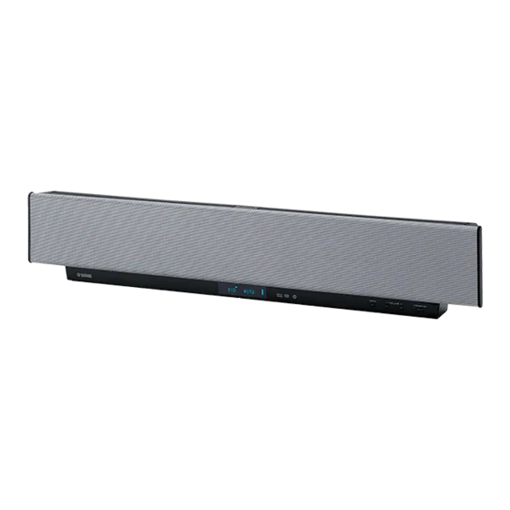
Yamaha digital sound projector owner's manual
Hide thumbs
Also See for YSP-1:
- Owner's manual (452 pages) ,
- Service manual (68 pages) ,
- Brochure (8 pages)
Table of Contents
Advertisement
Quick Links
Advertisement
Table of Contents

Related Manuals for Yamaha YSP-1


Summary of Contents for Yamaha YSP-1
- Page 1 UBTK YSP-1 Digital Sound Projector OWNER'S MANUAL...
-
Page 2: Important Safety Instructions
IMPORTANT SAFETY INSTRUCTIONS CAUTION RISK OF ELECTRIC SHOCK DO NOT OPEN CAUTION: TO REDUCE THE RISK OF ELECTRIC SHOCK, DO NOT REMOVE COVER (OR BACK). NO USER-SERVICEABLE PARTS INSIDE. REFER SERVICING TO QUALIFIED SERVICE PERSONNEL. * Explanation of Graphical Symbols The lightning flash with arrowhead symbol, within an equilateral triangle, is intended to alert you to the presence... - Page 3 Yamaha Corporation of America or its subsidiaries. Since hearing damage from loud sounds is often undetectable until it is too late, YAMAHA and the Electronic Industries Association’s Consumer Electronics Group recommend you to avoid pro- longed exposure from excessive volume levels.
- Page 4 Keep it in a safe place for future reference. Install this sound system in a well ventilated, cool, dry, clean place with at least 5 cm of space above (or below) YSP-1 – away from direct sunlight, heat sources, vibration, dust, moisture, and/ or cold.
- Page 5 CAUTION: READ THIS BEFORE OPERATING YOUR UNIT. CAUTION Danger of explosion if battery is incorrectly replaced. Replace only with the same or equivalent type. CAUTION Use of controls or adjustments or performance of procedures other than those specified herein may result in hazardous radiation exposure.
-
Page 6: How To Use This Manual
HOW TO USE THIS MANUAL Check that you have received all of the supplied accessories. (See “Supplied accessories” on page 4.) Install this unit in your listening room. (See “INSTALLING THIS UNIT IN YOUR LISTENING ROOM” on page 9.) Connect this unit to your TV and other external components. (See “CONNECTIONS”... -
Page 7: Table Of Contents
INTRODUCTION OVERVIEW ... 2 Selecting a listening room ... 4 About this manual... 4 Supplied accessories ... 4 CONTROLS AND FUNCTIONS ... 5 Front panel ... 5 Front panel display ... 6 Bottom panel... 7 Remote control... 8 PREPARATION INSTALLING THIS UNIT IN YOUR LISTENING ROOM ... -
Page 8: Overview
YAMAHA’s YSP-1 Digital Sound Projector challenges this preconception that complicated speaker set up and troublesome wiring go hand-in-hand with the enjoyment of multi-channel surround sound. - Page 9 DVDs, Dolby Pro Logic for the reproduction of true-to-life sound, and DTS for playback of the best possible sound clarity. Equipped with two optical digital, one coaxial digital and two analog input jacks, the YSP-1 allows you to expand your system through the direct connection of external components, such as a DVD player.
-
Page 10: Selecting A Listening Room
• Rooms where objects such as furniture are likely to obstruct the path of sound beams About this manual • This manual describes how to connect and operate the YSP-1. For details regarding the operation of external components, refer to the supplied owner’s manual for the component. -
Page 11: Controls And Functions
CONTROLS AND FUNCTIONS Front panel 1 Front panel display Shows information about the operational status of this unit. 2 Remote control sensor Receives signals from the remote control. 3 INPUT Switches between the connected external audio sources. 4 VOLUME –/+ Controls the output level of all audio channels (see page 30). -
Page 12: Front Panel Display
CONTROLS AND FUNCTIONS Front panel display NIGHT SLEEP 1 NIGHT indicator Lights up when you select a night listening mode (see page 33). 2 SLEEP indicator Lights up while the sleep timer is on (see page 50). 3 Decoder indicators When any of this unit’s decoders function, the respective indicator lights up. -
Page 13: Bottom Panel
SYSTEM CONNECTOR RS-232C 1 SYSTEM CONNECTOR jack Use to connect a YAMAHA subwoofer equipped with a SYSTEM CONNECTOR jack to this unit (see page 16). 2 RS-232C terminal This is a control expansion terminal for commercial use only (see page 17). -
Page 14: Remote Control
CONTROLS AND FUNCTIONS Remote control This section describes the function of each control on the remote control used to control this system. To operate other components, see “Controlling other components” on page 52. STANDBY/ON POWER CODE SET NIGHT SURROUND SET MENU CH LEVEL SELECT TEST... -
Page 15: Installing This Unit In Your Listening Room
INSTALLING THIS UNIT IN YOUR LISTENING ROOM This section describes how to choose a suitable installation location for this unit, and how to install the unit using either a metal wall bracket, rack or stand. Note If objects such as furniture are obstructing the path of sound beams, the desired surround sound effects may not be achieved. Make sure you install this unit where there are no objects in the path of sound beams. -
Page 16: Using A Metal Wall Bracket
Before installing, make sure that the rack is large enough to allow adequate ventilation space around this unit, and that it is strong enough to support the weight of both this unit and your TV. When the YSP-1 is installed under your TV Affixing this unit Stand... -
Page 17: Connections
12 to 17. CAUTION Do not connect this unit or other components to the mains power until all connections between components are complete. Audio connection Video connection YSP-1 Subwoofer Digital satellite tuner, cable TV or DVD player game console... -
Page 18: Connecting A Tv
You can connect a TV to this unit and display the OSD for easy viewing (see page 20) when operating SET MENU (see page 24). When connecting the Optical Cable, use the Cable Holder at the rear panel of the YSP-1 to fix the cable (see page 15). -
Page 19: Connecting A Dvd Player/Recorder
If there is no coaxial digital output jack on your DVD player/recorder, use them with optical digital connection. Cables used for connections Digital Audio Pin Cable (supplied) SYSTEM CONNECTOR RS-232C COAXIAL YSP-1 (Bottom panel) DIGITAL INPUT VIDEO SUBWOOFER OPTICAL Coaxial digital output... -
Page 20: Connecting A Vcr
Connect red plugs to the right jacks and white plugs to the left jacks. Cables used for connections Audio Pin Cable (White) (Red) SYSTEM RS-232C COAXIAL CONNECTOR (White) (Red) YSP-1 (Bottom panel) DIGITAL INPUT VIDEO SUBWOOFER OPTICAL (White) (Red) Analog audio output AUDIO INPUT (Red) -
Page 21: Connecting Other External Components
You can connect a DVD player/recorder or a component that supports optical digital connections. Cables used for connections Optical Cable SYSTEM CONNECTOR RS-232C COAXIAL YSP-1 (Bottom panel) DIGITAL INPUT VIDEO SUBWOOFER OPTICAL To prevent cables from becoming unplugged, place the cable holder... -
Page 22: Connecting A Subwoofer
(SUBWOOFER OUT) on this unit. When connecting a YAMAHA subwoofer equipped with a SYSTEM CONNECTOR jack, connect it to the SYSTEM CONNECTOR jack on this unit. If the subwoofer is connected using a system type connection, changing the power mode of this unit controls the power mode of the subwoofer. -
Page 23: Connecting The Power Supply Cable
The RS-232C terminal on the bottom panel of this unit does not support normal external component connection. This is a control expansion terminal for commercial use only. SYSTEM CONNECTOR RS-232C RS-232C terminal To an AC outlet YSP-1 (Bottom panel) DIGITAL INPUT VIDEO SUBWOOFER COAXIAL OPTICAL CONNECTIONS... -
Page 24: Preparing The Remote Control
PREPARING THE REMOTE CONTROL PREPARING THE REMOTE CONTROL Installing batteries in the remote control Press Press the mark on the battery cover and slide off the cover. Insert the two supplied batteries (AA, R06, UM-3) into the battery compartment. Make sure you insert the batteries according to the polarity markings (+/–). -
Page 25: Basic Operation
Using the remote control The remote control transmits a directional infrared beam. Use the remote control within 6 m (20 feet) of this unit and point it toward the remote control sensor on the main unit during operation. 30˚ 30˚ Handling the remote control •... -
Page 26: Steps To Enjoying Surround Sound
STEPS TO ENJOYING SURROUND SOUND STEPS TO ENJOYING SURROUND SOUND This section describes very simply how to display this unit’s OSD on your TV screen and set the parameters for your listening room. Once this is complete, you can enjoy real surround sound while watching TV in the comfort of your own home. -
Page 27: Selecting A Preset Listening Environment
Selecting a preset listening environment For real surround sound, select the preset listening room type (see below) that best matches your own listening environment. If none of the selections available are suitable for your listening environment, proceed to EASY SETUP (page 24) to make your own listening environment settings. -
Page 28: Enjoying Tv In Surround Sound
STEPS TO ENJOYING SURROUND SOUND Press SELECT once more. The parameters for the selected room type are loaded. ;MEMORY LOAD SELECT SELECT USER1 Loading ! [<]/[>]:Select Once the parameters are loaded, the display returns to the following screen. SET MENU . - Page 29 To select a surround mode, press SURROUND repeatedly (or press SURROUND, then press remote control. Signals input from 2-channel sources are played back on multiple channels. For more information on surround modes, see page 32. SURROUND SURROUND • To make more detailed listening environment settings, see page 24.
-
Page 30: Easy Setup
EASY SETUP If the preset listening environment settings available in “Selecting a preset listening environment” do not match the characteristics of your listening room, follow the procedure below to set each listening environment parameter individually using EASY SETUP. ROOM TYPE > SP POSITION (Speaker position) > ROOM SIZE •... - Page 31 Press SELECT once more. The display switches between the SQUARE and RECTANGLE selection screens. 1 ROOM TYPE ? [<]/[>]:Select [SELECT]:Enter SELECT 1 ROOM TYPE ? [<]/[>]:Select [SELECT]:Enter Press to select the desired setting, then press SELECT. SELECT SELECT Select the shape that best suits your listening room. •...
- Page 32 EASY SETUP SQUARE (Square) If you selected SQUARE in “ROOM TYPE (Room type)” on page 24: LEFT (Left) CENTER (Center) RECTANGLE (Rectangle) If you selected RECTANGLE in “ROOM TYPE (Room type)” on page 24: WIDE LEFT (Wide wall left) NARROW LEFT (Narrow wall left) RIGHT (Right) WIDE CENTER...
- Page 33 ROOM SIZE (Room size) Check that the following screen is displayed on your TV. If this screen is not displayed, make the settings in “SP POSITION (Speaker position)”. ;EASY SETUP LE.E* SQUARE EQ.>* CENTER LE.E3 ROOM SIZE ? LE.E4 Push [SELECT] Key. Press SELECT.
- Page 34 EASY SETUP SMALL (Small listening room) 3.8 m (12.5ft) • Select SMALL if both the width (W) and depth (D) of your listening room are 3.8 m (12.5ft), or the width (W) is approximately 3.4 m (11.2ft) and the depth (D) approximately 4.2 m (13.8ft). MID (Medium-sized listening room) 5.4 m (17.7ft) •...
- Page 35 SETUP OK (Register settings) Check that the following screen is displayed on your TV. If this screen is not displayed, make the settings in “ROOM SIZE (Room size)”. ;EASY SETUP LE.E* SQUARE EQ..* CENTER LE.E* MID . 4 SETUP OK ? Push [SELECT] Key.
-
Page 36: Volume Controls
VOLUME CONTROLS Adjusting the volume INPUT VOLUME STANDBY/ON TV VOL VOLUME MUTE TV MUTE TV INPUT To increase the volume output level, press VOLUME +/–. Adjustment range: 0.0 dB to –99.5 dB, MUTE (mute) VOLUME – Front panel Remote control VOLUME CONTROLS Muting the sound Press MUTE. -
Page 37: Playback
Selecting an input source You can playback sound and/or images from the various components connected to this unit simply by pressing one of the input selector buttons (TV, DVD, VCR or AUX) on the remote control. TV MUTE TV INPUT SLEEP To playback a TV program Press TV. -
Page 38: Selecting A Surround Mode
SELECTING A SURROUND MODE SELECTING A SURROUND MODE Playback sources and their available surround modes Depending on the playback source and selected surround mode, the indicators in the front panel display light up as follows. During CD playback: During DTS Digital signal input or when DTS Neo:6 is selected: During Dolby Digital signal input: DIGITAL... -
Page 39: Surround Mode Parameters
Surround mode parameters You can configure the parameters for Dolby Pro Logic II Music and DTS Neo:6 Music to fine-tune the surround sound effect. Press to select the parameter. Press / to configure the parameter. PANORAMA (when selecting PLII Music) Gives front L/R channel sound a wraparound effect, distributed throughout the entire surround sound field, for an expansive feeling. -
Page 40: Adjusting Beam Mode Settings
ADJUSTING BEAM MODE SETTINGS ADJUSTING BEAM MODE SETTINGS You can change the beam mode to suit the input source for this unit using the beam mode buttons. You can switch between: stereo mode for 2-channel sources, 3 beam mode and 5 beam mode and ST(STEREO)+3 beam mode for 5.1-channel playback. -
Page 41: St(Stereo)+3 Beam Mode
ADJUSTING BEAM MODE SETTINGS ST(STEREO)+3 beam mode Outputs sound beams to the front left and right, center, and surround left and right speaker positions. This mode is ideal when watching live recordings on DVD. Vocals and instrumental sounds can be heard close to the center of the listening position, while sound reflections from the venue itself can be heard to your right and left, giving you the feeling that you are... -
Page 42: Manual Setup
MANUAL SETUP To achieve the best quality surround sound, you can use MANUAL SETUP to fine-tune the listening environment parameters, as well as make advanced settings for speaker positions, sound beams, digital input and the OSD. Change the initial settings (indicated in bold under each parameter) to reflect the needs of your own listening environment. -
Page 43: Using Set Menu
Using SET MENU Use the remote control to access and adjust each parameter. NIGHT SURROUND SET MENU CH LEVEL MENU SELECT RETURN TEST VOLUME You can change SET MENU parameters while the unit is reproducing sound. Press SET MENU. The SET MENU screen appears on your TV. The operation buttons for SET MENU are displayed at the bottom of the screen. -
Page 44: Sound Menu
MANUAL SETUP SOUND MENU Use the manually adjust any speaker setting or compensate for video signal processing delays. (SET MENU → MANUAL SETUP → SOUND MENU) 1 SOUND MENU 1/2 . A)SUBWOOFER SET B)SPEAKER LEVEL C)DYNAMIC RANGE D)AUDIO SET [ ]/[ ]:Up/Down [SELECT]:Enter SUBWOOFER SET (Subwoofer set) Use to manually adjust subwoofer settings. - Page 45 DYNAMIC RANGE (Dynamic range) Use to select the amount of dynamic range compression to be applied to the speakers. This setting is effective only when the unit is decoding Dolby Digital and DTS signals. Dynamic range is the difference between the smallest sound that can be heard above the noise of the equipment and the biggest sound that can be heard without distortion.
-
Page 46: Beam Menu
Use to adjust the height of this unit from the floor. Choices: 0 m to 3.0 m (0 ft to 10.0 ft) Initial setting: 1.0 m (3.5 ft) YSP-1 Floor ROOM WIDTH (LEFT WALL) (Width of listening room left wall) If SP POSITION is set to WALL, use this to set the width of your listening room. - Page 47 USER POSITION (User position) Use to set the distance of the listening position from this unit. Choices: 2.0 m to 9.0 m (6.5 ft to 30.0 ft) TO L WALL (Listening position to left wall) If SP POSITION is set to WALL, use to set the distance of the center of this unit from the left wall.
- Page 48 MANUAL SETUP DISTANCE (Distance) You can use this to set the distance beams travel after being output and reflected off the wall, until they arrive at the listening position for each speaker. The lines in the illustration below indicate the distance. Choices: 0.3 m to 24.0 m (1.0 ft to 80.0 ft) •...
- Page 49 IMAGE LOCATION (Image location) You can adjust the direction from which front left and right speaker sound is heard by directing these audio signals so that they are also output from the center speaker. Use this feature to redirect audio signals if the sound coming from the left and right speakers seems unnatural, such as when your listening position is not the center of your listening room.
-
Page 50: Input Menu
MANUAL SETUP INPUT MENU Use to reassign digital input from external components connected to this unit. (SET MENU → MANUAL SETUP → INPUT MENU) 3 INPUT MENU . A)INPUT ASSIGNMENT B)INPUT MODE C)INPUT RENAME [ ]/[ ]:Up/Down [SELECT]:Enter INPUT ASSIGNMENT (Input assignment) You can assign the optical and coaxial digital input jacks of this unit to other components if this unit’s initial settings do not correspond to your needs. -
Page 51: Option Menu
Press to select the character you want. • You can use up to 8 characters for each input. • Press to change the character in the following order, or press to go in the reverse order: A to Z, a space, 0 to 9, a space, a to z, a space, #, *, +, etc. - Page 52 MANUAL SETUP UNIT SET (Unit settings) You can use this to change the display unit of measurement. Choices: METERS, FEET B)UNIT SET )METERS FEET [<]/[>]:Select [SELECT]:Retern • Select METERS to input speaker distances in meters. • Select FEET to input speaker distances in feet.
-
Page 53: Selecting An Input Mode
SELECTING AN INPUT MODE You can select the type of input signals you want this unit to use. INPUT VOLUME STANDBY/ON TV MUTE TV INPUT SLEEP Press and hold INPUT on the front panel, or an input selector button on the remote control. -
Page 54: Manually Adjusting Output Levels
MANUALLY ADJUSTING OUTPUT LEVELS MANUALLY ADJUSTING OUTPUT LEVELS You can adjust the output level of each speaker to achieve a more true-to-life surround sound experience. You can adjust the sound beam output levels for each beam mode. Using the test tone You can use the test tone feature to output a test tone from each speaker to manually balance the speaker levels. -
Page 55: Adjusting Output Levels During Playback
Adjusting output levels during playback You can also manually adjust the speaker levels while playing back a source, such as a DVD. NIGHT SURROUND SET MENU CH LEVEL MENU SELECT TEST RETURN Press CH LEVEL. CH LEVEL Press to select the speaker you want to adjust. -
Page 56: Using The Sleep Timer
USING THE SLEEP TIMER Use this feature to automatically set this unit in the standby mode after a specified time period. The sleep timer is useful when you are going to sleep while this unit is playing a source. Setting the sleep timer TEST TV VOL VOLUME... -
Page 57: Remote Control Features
REMOTE CONTROL FEATURES In addition to controlling this unit, the remote control can also operate other A/V components made by YAMAHA and other manufacturers. To control other components, you must set up the remote control with the appropriate remote control codes. -
Page 58: Controlling Other Components
REMOTE CONTROL FEATURES Controlling other components Operating your TV STANDBY/ON CODE SET NIGHT SURROUND SET MENU CH LEVEL SELECT TEST TV VOL VOLUME MUTE TV MUTE TV INPUT SLEEP Press TV to switch the input to TV. 1 POWER Turns on/off the TV’s power. 2 Numeric buttons Selects a TV channel for playback. - Page 59 Use to perform VCR player operations, such as play and stop. Returning to theYSP-1 operation mode To return to the YSP-1 operation mode, press one of the following keys. For details on each key, see page 8 or 20. NIGHT...
-
Page 60: Troubleshooting
Refer to the chart below when this unit does not function properly. If the problem you are experiencing is not listed below or if the instruction below does not help, set this unit to the standby mode, disconnect the power cord, and contact the nearest authorized YAMAHA dealer or service center. General... - Page 61 Problem Surround sound The listening room is not a regular shape. effects are insubstantial. There is no wall in the path of the beam. Dolby Digital or DTS The connected component is not set to sources cannot be output Dolby Digital or DTS digital played.
- Page 62 TROUBLESHOOTING Remote control Problem The remote control Wrong distance or angle. does not work and/or function properly. Direct sunlight or lighting (from an inverter type of fluorescent lamp, etc.) is striking the remote control sensor of this unit. The batteries are weak. You cannot operate The external component you want to external components...
-
Page 63: Resetting The Factory Presets
RESETTING THE FACTORY PRESETS If you want to reset all of your unit’s parameters for any reason, do the following. This procedure completely resets ALL the parameters in SET MENU. Note After performing the following procedure you must reset the ROOM TYPE, SP POSITION and ROOM SIZE parameters to match your surround sound environment. -
Page 64: Front Panel Display Items
FRONT PANEL DISPLAY ITEMS FRONT PANEL DISPLAY ITEMS POWER STANDBY/ON VOLUME -40.0dB EASY SETUP ROOM TYPE 1 ROOM TYPE? SP POSITION 2 SP POSITION? ROOM SIZE 3 ROOM SIZE? SETUP OK 4 SETUP OK? MANUAL SETUP SOUND MENU 1 SOUND MENU BEAM MENU 2 BEAM MENU INPUT MENU... -
Page 65: Glossary
Audio formats Dolby Digital Dolby Digital is a digital surround sound system that gives you completely independent multi-channel audio. With 3 front channels (left, center, and right), and 2 surround stereo channels, Dolby Digital provides 5 full-range audio channels. With an additional channel especially for bass effects, called LFE (low frequency effect), the system has a total of 5.1-channels (LFE is counted as 0.1 channel). -
Page 66: Index
INDEX Audio Pin Cable ... 12 Beam modes ... 34 Coaxial digital output jack ... 13 Coaxial digital input jack ... 13 Digital Audio Pin Cable ... 13 Display... 6, 20 Dolby Digital ... 32 Dolby Pro Logic ... 32 Dolby Pro Logic II... -
Page 67: Specifications
AMP SECTION • Maximum Output Power (EIAJ) ...2 W (1 kHz, 10% THD, 10 Ω) × 40 20 W (100 Hz, 10% THD, 4 Ω) × 2 SPEAKER SECTION Small dia. speakers ... 4 cm (1.5”)-cone magnetic shielding type× 40 Woofers... -
Page 68: Dvd Player
TELEFUNKUN 269, 264, 265, 266 DAYTRON THOMSON DUAL TOSHIBA DWIN 293, 281 VIDECH EMERSON 297, 224, 239, 232 WARDS FURGUSON 223, 265, 266 YAMAHA FIRST LINE FISHER 295, 233 ZENITH FRABA FUJITSU DVD PLAYER FUNAI 277, 278 293, 297, 234, AIWA 235, 236... - Page 69 CABLE 739, 752, 753, 755, 758, 759, 762 GENERAL INSTRUMENT HAMIN 723, 724, 725, 726, 727 HITACHI JEROLD 722, 728, 729, 732, 733, 734, 735, 736, 737 MAGNAVOX MOTOROLA 739, 742, 743 PANASONIC 744, 745, 746, 747 PHILLIPS 763, 764, 765, 766, 767, 768 PIONEER RADIO SHACK749...
- Page 70 YAMAHA ELECTRONICS (UK) LTD. YAMAHA HOUSE, 200 RICKMANSWORTH ROAD WATFORD, HERTS WD18 7GQ, ENGLAND YAMAHA SCANDINAVIA A.B. J A WETTERGRENS GATA 1, BOX 30053, 400 43 VÄSTRA FRÖLUNDA, SWEDEN YAMAHA MUSIC AUSTRALIA PTY, LTD. 17-33 MARKET ST., SOUTH MELBOURNE, 3205 VIC., AUSTRALIA...