Yamaha YSP-1 Service Manual
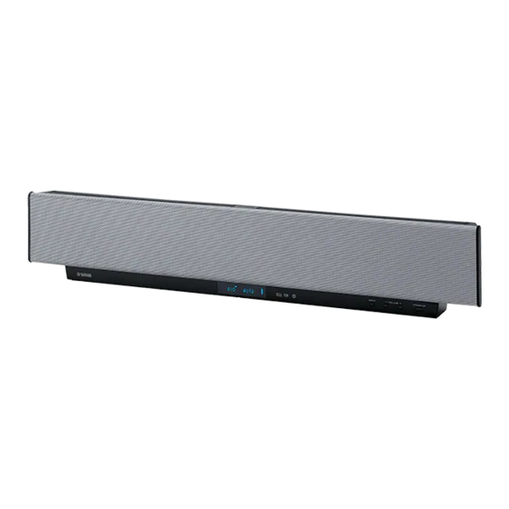
Digital sound projector
Hide thumbs
Also See for YSP-1:
- Owner's manual (452 pages) ,
- Brochure (8 pages) ,
- Product catalog (44 pages)
Table of Contents
Advertisement
This manual has been provided for the use of authorized YAMAHA Retailers and their service personnel.
It has been assumed that basic service procedures inherent to the industry, and more specifically YAMAHA Products, are already
known and understood by the users, and have therefore not been restated.
WARNING:
IMPORTANT:
The data provided is believed to be accurate and applicable to the unit(s) indicated on the cover. The research, engineering, and
service departments of YAMAHA are continually striving to improve YAMAHA products. Modifications are, therefore, inevitable
and specifications are subject to change without notice or obligation to retrofit. Should any discrepancy appear to exist, please
contact the distributor's Service Division.
WARNING:
IMPORTANT:
I CONTENTS
TO SERVICE PERSONNEL .......................................... 2
FRONT PANEL .............................................................. 3
REAR PANELS .............................................................. 3
REMOTE CONTROL PANELS ...................................... 4
INTERNAL VIEW ........................................................... 5
SET MENU TABLE ........................................................ 6
..................................... 13~19
1 0 0 9 3 1
DIGITAL SOUND PROJECTOR
IMPORTANT NOTICE
Failure to follow appropriate service and safety procedures when servicing this product may result in personal
injury, destruction of expensive components, and failure of the product to perform as specified. For these reasons,
we advise all YAMAHA product owners that any service required should be performed by an authorized
YAMAHA Retailer or the appointed service representative.
The presentation or sale of this manual to any individual or firm does not constitute authorization, certification or
recognition of any applicable technical capabilities, or establish a principle-agent relationship of any form.
Static discharges can destroy expensive components. Discharge any static electricity your body may have
accumulated by grounding yourself to the ground buss in the unit (heavy gauge black wires connect to this buss).
Turn the unit OFF during disassembly and part replacement. Recheck all work before you apply power to the unit.
4
........... 7~12
YSP-1
SERVICE MANUAL
DISPLAY DATA ........................................................... 37
IC DATA ................................................................. 38~39
BLOCK DIAGRAM ....................................................... 40
PRINTED CIRCUIT BOARD .................................. 41~49
PIN CONNECTION DIAGRAM .................................... 50
SCHEMATIC DIAGRAM ........................................ 51~54
PARTS LIST ........................................................... 55~66
REMOTE CONTROL .................................................... 67
20~36
P.O.Box 1, Hamamatsu, Japan
'05.01
Advertisement
Table of Contents

Related Manuals for Yamaha YSP-1


Summary of Contents for Yamaha YSP-1
-
Page 1: Table Of Contents
This manual has been provided for the use of authorized YAMAHA Retailers and their service personnel. It has been assumed that basic service procedures inherent to the industry, and more specifically YAMAHA Products, are already known and understood by the users, and have therefore not been restated. -
Page 2: To Service Personnel
YSP-1 I TO SERVICE PERSONNEL AC LEAKAGE WALL EQUIPMENT TESTER OR 1. Critical Components Information OUTLET UNDER TEST EQUIVALENT Components having special characteristics are marked s and must be replaced with parts having specifications equal to those originally installed. 2. Leakage Current Measurement (For 120V Models Only) -
Page 3: Front Panel
YSP-1 FRONT PANEL J model only REAR PANELS BOTTOM VIEW U, C models R model T model K model A model B, G models L model J model... -
Page 4: Remote Control Panels
YSP-1 I REMOTE CONTROL PANELS I SPECIFICATIONS / U, C, R, T, K, A, B, G, L models I Audio Section Minimum RMS Output Power (Power Amp. Section) Woofer [100Hz, 10%THD, 4 ohms] ......... 20W x 2 Tweeter [1kHz, 10%THD, 10 ohms] ........ 2W x 40 Input Jack AUX, TV .............. -
Page 5: Internal View
YSP-1 I INTERNAL VIEW Manufactured under license from Dolby Laboratories. “Dolby”, “Pro Logic”, and the double-D symbol are trademarks of Dolby Laboratories. FRONT VIEW 1 DRIVER, WOOFER 2 DRIVER, TWEETER 3 INPUT (3) P.C.B. 4 INPUT (4) P.C.B. “DTS”, and “Neo:6” are trademarks of Digital Theater Systems, Inc. -
Page 6: Set Menu Table
YSP-1... -
Page 7: Disassembly Procedures
YSP-1 I DISASSEMBLY PROCEDURES / (Remove parts in the order as numbered.) Cautions for disassembly and reassembly : • Disconnect the power cable from the AC outlet. • Spread soft cloth or the like and perform the work on it. - Page 8 YSP-1 Fig. 2 2. Removal of Rear Unit a. Remove 22 screws (3). (Fig. 2) b. Remove CB7, CB10 and CB14. (Fig. 3) c. Remove the Rear Unit. Rear Unit CB14 CB10 Fig. 3 When checking the P.C.B. : • The Rear Unit removed from the unit does not work because its grounding is loose.
- Page 9 YSP-1 Plate/ Shield Pad L Fig. 4 3. Removal of INPUT (2) P.C.B. a. Remove 14 screws (4). (Fig. 4) b. Remove 3 pad L’s. (Fig. 4) c. Remove the Plate/Shield. d. Remove 4 screws (5). (Fig. 5) e. Remove CB7, CB9 and CB302. (Fig. 5) f.
- Page 10 YSP-1 Front Panel Unit Fig. 7 5. Removal of Front Panel Unit a. Remove 17 screws (8). (Fig. 7) b. Remove the Front Panel Unit. c. Remove 2 screws (9). (Fig. 8) d. Remove the Stopper frame. Stopper Frame Fig. 8 6.
- Page 11 YSP-1 Fig. 11 Installation of Driver (Tweeter) Caution : Make sure that all the removed Driver (tweeter) parts are reinstalled at specified positions. (Fig. B) REAR VIEW Rch side Lch side Fig. B Rch side / Lch side / Pin No. / 1 –...
- Page 12 YSP-1 7. Removal of Driver (Woofer) a. Remove 4 screws (B). (Fig. 12) b. Remove the Side covers L/R. c. Remove the Plate/Cover. d. Remove 4 screws (C). (Fig. 12) e. Remove the Plate/Side. f. Remove 18 screws (D). (Fig. 12) g.
-
Page 13: Updating Firmware
YSP-1 I UPDATING FIRMWARE / After replacing the following parts with the replacement parts, update the firmware. P.C.B. ASS’Y DSP : WE218400 IC304 of P.C.B. ASS’Y DSP : X3601A00 IC2 of P.C.B. ASS’Y DSP : X6210B00 G Required tools • DOS/V machine, OS: Windows 98/2000/Me/XP, PC with a serial port (RS232C) •... - Page 14 YSP-1 G Operation Procedure For CPU 1. Install FlashSta.exe into the PC. 2. Before turning on the power to YSP-1 and PC, connect between RS232C ports with the RS232C cable (cross cable). (Fig. 1) BOTTOM VIEW Reset Switch RS-232C Port Fig.
- Page 15 YSP-1 6. Press the [Refer...] button. And select the firmware name. * The ID code is loaded when the file is selected. Select M16/20 62 Press this button to open the window 7. Press the [Setting] button and set the transmission rate.
- Page 16 The press the [OK] button to end the procedure. For DSP 1. Install spDownloader_2_0_7_xxx.exe into the PC. 2. Before turning on the power to YSP-1 and PC, connect between RS232C ports with the RS232C cable (cross cable). (Fig. 1) 3. Connect the power cable of YSP-1 to the AC outlet.
- Page 17 YSP-1 4. Start up spDownloader_2_0_7_xxx.exe, the screen will appear as shown below. 5. Select the data to be transmitted and port. · COM Port Select the port of RS-232C. · D/load Protocol Select “SPCM Protocol” Select the port of RS-232C Select SPCM Protocol 6.
- Page 18 YSP-1 2 Confirm Software Target and press the [Download] button. Firm Software Target DSP application SPCM Application SPID SPCM init Data SPCM CSC * When Source filename is selected, Software Target box is selected automatically. * If Software Target is different, confirm again Source filename or re-open spDownloader.
- Page 19 YSP-1 7. Press the “STANDBY/ON” key of the YSP-1 to turn off the power. 8. While pressing the “VOL+” key and “VOL-” key of the YSP-1, press the “STANDBY/ON” key of the remote controller to activate the DIAG function. 1 Using the “UP” or “DOWN” key of the remote controller, select the DIAG menu in the figure below.
-
Page 20: Self Diagnosis Function (Diag
YSP-1 I SELF DIAGNOSIS FUNCTION (DIAG) / There are 14 DIAG menu items, each of which has sub- menu items. Listed in the table below are menu items and sub-menu items. DIAG MENU SUB MENU DSP THROUGH 1. ALL (YSS948-YSS930) 2. - Page 21 YSP-1 • Starting DIAG To activate the DIAG function, press the “STANDBY/ON” key of the remote controller while pressing the keys of the main unit as shown below at the same time. Keys of main unit Turn on the power while pressing these keys.
- Page 22 YSP-1 • Display provided when DIAG started When the monitor is connected, DIAGNOSTIC MENU appears on its screen as shown in the figure. (It remains on display until DIAG is cancelled.) The FL display of the main unit displays the protection function history data and the version (1 alphabet) and the DIAG menu [sub-menu (THR ALL) of DIAG menu No.1...
- Page 23 YSP-1 • History of protection function When the protection function has worked, its history is stored in memory with a backup. Even if no abnormality is noted while servicing the unit, an abnormality which has occurred previously can be defined as long as the backup data has been stored.
- Page 24 YSP-1 • Functions in DIAG mode In addition to the DIAG menu items, functions as listed below are available. • Input selection • Muting • Night • Power on/off • Master volume * Functions related to the set menu are not available.
- Page 25 YSP-1 • Details of DIAG menu With full-bit output specified in some modes, it is possible to execute 0dBFS output without head margin in each channel. 1. DSP THROUGH This function is for YSS930 only. Main DSP of YSS930 is selected for FRONT output.
- Page 26 YSP-1 DSP THR CENTER • CENTER output without the head margin is provided in digital full bit. • The SWFR signal is output but not in digital full bit. DSP THR FRONT R • FRONT R output without the head margin is provided in digital full bit.
- Page 27 YSP-1 2. PRO LOGIC / NEO6 PRO LOGIC I, II, Neo:6 can be selected from the SUB menu items. PRO LOGIC I PRO LOGIC II Neo:6 PRO LOGIC/NEO:6 (ANALOG) Analog (Shaded items not used in this example) Note : The analog signal level can not be confirmed...
- Page 28 YSP-1 3. EFFECT OFF / DISPLAY CHECK This program is used to check the FL display section. The display condition varies as shown below according to the sub-menu operation. The signals are processed using EFFECT OFF (The L/R signal is output using ANALOG MAIN BYPASS.)
- Page 29 YSP-1 4. MANUAL TEST The noise generator with a built-in DSP outputs the test noise through the channels specified by the sub-menu. The noise frequency for LFE is 35 to 250 Hz. Other than that, the center frequency is 800Hz.
- Page 30 YSP-1 6. FACTORY PRESET This menu is used to reserve and inhibit initialization of the back-up RAM. The signals are processed using EFFECT OFF. (The L/R signal is output using ANALOG MAIN BYPASS.) PRESET INHIBIT (Initialization inhibited) / RAM initialization is not executed. Select this sub-menu to protect the values set by the user.
- Page 31 YSP-1 7. AD DATA CHECK This menu is used to display the A/D conversion value of the main CPU which detects panel keys of the main unit and protection functions in % using the sub-menu. During signal processing, the condition before execution is maintained.
- Page 32 YSP-1 9. IF STATUS (Input function status) Using the sub-menu, the status data is displayed one after another in the hexadecimal notation. During signal processing, the status before execution of this menu is maintained. * Numeric values in the figure example are for reference.
- Page 33 YSP-1 10. MODEL The information on the model, destination and video format is displayed. MODEL SETTING DESTINATION J, UC, ATLBG or RK is displayed. VIDEO FORMAT NTSC (J, UC, R, K models) PAL (T, A, BG, L models) 11. MICROPROCESSOR INFORMATION There are 4 SUB menu items.
- Page 34 YSP-1 12. DATE There are 4 SUB menu items. The updated date of the program, clearance of the protection history and the remote control reception code are displayed. When Remo Code menu is selected, keys become non- operable due to detection of the values of all keys.
- Page 35 YSP-1 13. 1 SP TEST ONE SP TEST Have the sound produced from each driver to check its condition and installation position. Use the “SELECT” and “RETURN” keys of the remote controller for selection. T01 T02 T03 T04 T05 T06 T07 T08 T09...
- Page 36 YSP-1 14. DSP VER The version of Application Code is displayed. The version of Core Start-Up Code is displayed. The version of SPID is displayed. * SPID is the abbreviation for the Sound Projector Module Initialization Data Format. The condition of the amplifier IC is displayed.
-
Page 37: Display Data
YSP-1 I DISPLAY DATA G V1 : 15-BT-99GNK (WE204600) PATTERN AREA G PIN CONNECTION Pin No. Connection 24 23 22 21 20 19 Pin No. Connection P32 P33 P34 P35 NX NX Note : 1) F1, F2 ..Filament 2) NP ..No pin 3) NX .. -
Page 38: Ic Data
YSP-1 I IC DATA IC304 : M30626FHPFP (DSP P.C.B) Single-Chip 16bit CMOS MICROCOMPUTER (Main CPU) Port P0 Port P1 Port P2 Port P3 Port P4 Port P5 Port P6 <VCC2 ports> <VCC1 ports> Internal peripheral functions A/D converter System clock... - Page 39 YSP-1 IC304 : M30626FHPFP (DSP P.C.B) IC304 : M30626FHPFP (DSP P.C.B) Single-Chip 16bit CMOS MICROCOMPUTER (Main CPU) Single-Chip 16bit CMOS MICROCOMPUTER (Main CPU) Name Port Function Name PORT Function S-OUT FL Driver TxD (Serial I/O-4) CLK OUT to E PO96...
-
Page 40: Block Diagram
YSP-1 I BLOCK DIAGRAM • See page 53 → • See page 51, 52 → • See page 54 → SCHEMATIC DIAGRAM SCHEMATIC DIAGRAM SCHEMATIC DIAGRAM INPUT IC311 IC26 IC27 1, 3 TV L/R Ch_1 4,15 1, 7 1, 2... -
Page 41: Printed Circuit Board
YSP-1 I PRINTED CIRCUIT BOARD (Foil side) AMP P .C.B. (Side A) Lead Free Solder Used AMP P.C.B. (Side B) Lead Free Solder Used Ref No. Location TXN9 TXP0 TXP9 TXN0 TXN8 TXP1 TXP8 TXN1 TXN7 TXP2 TXP7 TXN2 –... - Page 42 YSP-1 I PRINTED CIRCUIT BOARD (Foil side) DSP P.C.B. (Side A) Lead Free Solder Used INPUT (2) IC3 and IC4 can not be supplied. INPUT (2) Ref No. Location D300 D301 D302 D303 TEMP1 Nout2 AMP_PRT1 Pout2 Ppwm_r Npwm_r Nck2...
- Page 43 YSP-1 I PRINTED CIRCUIT BOARD (Foil side) DSP P.C.B. (Side B) Lead Free Solder Used Ref No. Location D305 D306...
- Page 44 YSP-1 I PRINTED CIRCUIT BOARD (Foil side) INPUT (1) P.C.B. (Side A) AUDIO INPUT DIGITAL INPUT SUBWOOFER VIDEO SYSTEM OPTICAL COAXIAL RS-232C CONNECTOR Reset Switch POW_RY PW_DOWN RESET S3.3BK S3.3 +3.3V +15V AGMD INPUT INPUT (2) INPUT (2) Ref No. Location...
- Page 45 YSP-1 I PRINTED CIRCUIT BOARD (Foil side) INPUT (1) P .C.B. (Side B) Lead Free Solder Used Ref No. Location Ref No. Location Ref No. Location IC26 IC27 IC39...
- Page 46 YSP-1 I PRINTED CIRCUIT BOARD (Foil side) INPUT ( 2 ) P.C.B. (Side A) INPUT ( 4 ) P.C.B. CB300 (Side A) INPUT (1) INPUT CB10 CB302 INPUT (3) DEST TEMP3 FAN_OUT OSD_TX AGND OSD_CLK OSD_CE I_SEL M_RTS SW_OUT M_CTS S3.3...
- Page 47 YSP-1 I PRINTED CIRCUIT BOARD (Foil side) INPUT ( 2 ) P.C.B. (Side B) Lead Free Solder Used INPUT ( 4 ) P.C.B. (Side B) Lead Free Solder Used INPUT ( 3 ) P.C.B. (Side B) Lead Free Solder Used...
- Page 48 YSP-1 I PRINTED CIRCUIT BOARD (Foil side) INPUT (5) P.C.B. (Side A) INPUT (2) Ref No. Location IC40 AGMD +15V +3.3V SWITCHING +15V POWER SUPPLY UNIT +15V S3.3 +15V S3.3BK +15V RESET PW_DOWN POW_RY INPUT AC IN SWITCHING POWER SUPPLY UNIT...
-
Page 49: Printed Circuit Board
YSP-1 I PRINTED CIRCUIT BOARD (Foil side) INPUT ( 5 ) P.C.B. (Side B) Lead Free Solder Used Ref No. Location... -
Page 50: Pin Connection Diagram
YSP-1 I PIN CONNECTION DIAGRAM • ICs • Diodes AN77L04 NJM7805FA NJM2068MD S-29630AFJA SN74LVC2G08DCUR TPS2034D 1N4002S 1SS355 1SS380 MA8036 3.6V Anode MA8062 6.2V MA8110 11.0V Anode RB501V-40 Cathode 2: OUT 3: IN Cathode 1: IN 1: OUT 3: COM 2: COM µPC4570G2... -
Page 51: Schematic Diagram
YSP-1 SCHEMATIC DIAGRAM (DSP 1/2) IC3 and IC4 can not be supplied. / IC5: SN74LVC74APWR DUAL POSITIVE-EDGE-TRIGGERED D-TYPE FLIP-FLOPS This part can not be supplied This part can not be supplied This part can not be supplied This part can not be supplied... - Page 52 YSP-1 SCHEMATIC DIAGRAM (DSP 2/2) IC300: LC89057W-VF4-E 192kHz 24Bit 8ch DAC Page 53 Page 53 Page 53 to INPUT (2)_CB9 to INPUT (2)_W10 to INPUT (3)_W11 Audio MCLK LOUT1+ LRCK DATT LOUT1– BICK ROUT1+ SDTI1 DATT ANALOG IN ROUT1– SDTI2...
- Page 53 YSP-1 SCHEMATIC DIAGRAM (INPUT) IC1: M66003-0101FP IC2: MAX3232CDWR FL Display Driver On Screen Display Controller INPUT(1) INPUT(5) Display code CGROM SEG00 (8-bit x 60) (35 bit x 166) 14.1 Segment SEG25 Code output write SEG26 circuit DOUT1 CGROM Serial dot data...
-
Page 54: Schematic Diagram
YSP-1 SCHEMATIC DIAGRAM (AMP) DRIVER DRIVER (TWEETER) (TWEETER) Page 51 to DSP_CB1, CB2 Page 53 to INPUT (2)_W8, W9 IC1, 3: TAD108 Sound Projector Transducer Amplifier NEGATIVE CHPMP DC/DC VVOL controller TXP0 TXN8 10.8 15.0 -1.1 TRANSDUCER -2.2 10.8 TXN0... -
Page 55: Parts List
YSP-1 PARTS LIST I ELECTRICAL PARTS I WARNING Components having special characteristics are marked s and must be replaced with parts having specifications equal to those originally installed. ABBREVIATIONS IN THIS LIST ARE AS FOLLOWS: C.A.EL.CHP : CHIP ALUMI.ELECTROLYTIC CAP L.EMIT... - Page 56 YSP-1 P.C.B. DSP & P.C.B. AMP % : IC3 (TMS320C6713BGDP) and IC4 (TAC8256) can not be supplied. When IC3 and IC4 are failures, please exchange DSP P.C.B. (WE218400). ✻ New Parts...
- Page 57 YSP-1 P.C.B. AMP & P.C.B. INPUT ✻ New Parts...
- Page 58 YSP-1 P.C.B. INPUT ✻ New Parts...
- Page 59 YSP-1 P.C.B. INPUT ✻ New Parts...
- Page 60 YSP-1 P.C.B. INPUT ✻ New Parts...
- Page 61 YSP-1 Chip Parts ✻ New Parts...
- Page 62 YSP-1 Chip Parts ✻ New Parts...
-
Page 63: Parts List
YSP-1 Parts List for Carbon Resistors Value 1/4W Type Part No. 1/6W Type Part No. Value 1/4W Type Part No. 1/6W Type Part No. 1.0 Ω 3100 3100 10 kΩ 7100 7100 HJ35 HF85 HF45 HF45 1.8 Ω ❊ 3180 11 kΩ... - Page 64 YSP-1 I EXPLODED VIEW 3-51 3-46 3-31 3-105 3-12 3-51 3-107 3-106 3-105 3-1-3 3-102 3-101 3-105 3-105 3-105 3-3 (1) 3-110 3-108 MAIN UNIT 1-52 1-106 3-3 (3) 1-51 1-106 3-3 (4) 1-105 1-51 1-106 1-41 1-32 1-41...
- Page 65 YSP-1 I MECHANICAL PARTS 200-1 207-1 207-2 ✻ New Parts ✻ New Parts...
- Page 66 YSP-1 I MAIN UNIT I MECHANICAL PARTS 2-104 2-111 2-12 2-111 2-101 2-11 2-104 2-104 2-104 2-41 2-104 2-104 2-11 2-65 2-65 2-1-45 2-1-101 2-101 2-104 2-1-48 2-1-43 2-101 2-1-101 2-104 2-101 2-1-102 2-1-105 2-31 2-1-12 2-101 2-101 2-1-31 2-1-48...
-
Page 67: Remote Control
YSP-1 I REMOTE CONTROL CODE Function STANDBY/ON 78-0F – U, C, R, T, K, A, B, G, L models J model POWER AV – 50-17 – – – – 50-0D – – – – 50-0E – – – – 50-0F –... - Page 68 YSP-1...