Table of Contents
Advertisement
Quick Links
Advertisement
Table of Contents

Related Manuals for Cisco IC3000


Summary of Contents for Cisco IC3000
- Page 1 Cisco IC3000 Industrial Compute Gateway Hardware Installation Guide First Published: 2018-08-31 Last Modified: 2019-07-16 Americas Headquarters Cisco Systems, Inc. 170 West Tasman Drive San Jose, CA 95134-1706 http://www.cisco.com Tel: 408 526-4000 800 553-NETS (6387) Fax: 408 527-0883...
- Page 2 Cisco has more than 200 offices worldwide. Addresses and phone numbers are listed on the Cisco website at www.cisco.com/go/offices. Cisco and the Cisco logo are trademarks or registered trademarks of Cisco and/or its affiliates in the U.S. and other countries. To view a list of Cisco trademarks, go to this URL: www.cisco.com...
- Page 3 WARNING: IMPORTANT SAFETY INSTRUCTIONSMeans danger. You are in a situation that could cause bodily injury. Before you work on any equipment, be aware of the hazards involved with electrical circuitry and be familiar with standard practices for preventing accidents. Use the statement number Cisco IC3000 Industrial Compute Gateway Hardware Installation Guide...
-
Page 4: Safety Warnings
Verfahren zur Vorbeugung vor Unfällen vertraut. Suchen Sie mit der am Ende jeder Warnung angegebe Anweisungsnummer nach der jeweiligen Übersetzung in den übersetzten Sicherheitshinweisen, die zusam mit diesem Gerät ausgeliefert wurden. BEWAHREN SIE DIESE HINWEISE GUT AUF. Cisco IC3000 Industrial Compute Gateway Hardware Installation Guide... - Page 5 Använd det nummer som finns i slutet av varje varning för a dess översättning i de översatta säkerhetsvarningar som medföljer denna anordning. SPARA DESSA ANVISNINGAR Cisco IC3000 Industrial Compute Gateway Hardware Installation Guide...
- Page 6 Brug erklæringsnumm efter hver advarsel for at finde oversættelsen i de oversatte advarsler, der fulgte med denne enhed. GEM DISSE ANVISNINGER Cisco IC3000 Industrial Compute Gateway Hardware Installation Guide...
- Page 7 Preface Safety Warnings Cisco IC3000 Industrial Compute Gateway Hardware Installation Guide...
- Page 8 Material Safety Law prohibits the use of UL-certified cables (that have the “UL” shown on the code) for any other electrical devices than products designated by CISCO. The use of cables that are certified by Electrical Appliance and Material Safety Law (that have “PSE” shown on the code) is not limited to CISCO-designated products.
-
Page 9: Related Documentation
To search a PDF document in Adobe Reader, use the basic Find toolbar (Ctrl-F) or the Full Reader Search window (Shift-Ctrl-F). Use the Find toolbar to find words or phrases within a specific document. Use the Cisco IC3000 Industrial Compute Gateway Hardware Installation Guide... - Page 10 Searching Cisco Documents Full Reader Search window to search multiple PDF files simultaneously and to change case sensitivity and other options. Adobe Reader’s online help has more information about how to search PDF documents. Cisco IC3000 Industrial Compute Gateway Hardware Installation Guide...
-
Page 11: Product Overview
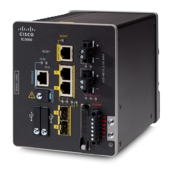
The term derives from the original specifications published by Deutsches Institut für Normung (DIN) in Germany. The Cisco IC3000 is low-power, fan-less, with Gigabit Ethernet and a dedicated management port. The SKU is IC3000-2C2F-K9. - Page 12 Product Overview General Description Figure 1: Cisco IC3000 SKU Figure 2: Cisco IC3000 Front Panel, on page 11 shows the front panel details of the Cisco IC3000. Cisco IC3000 Industrial Compute Gateway Hardware Installation Guide...
- Page 13 Console connector (RJ-45) Alarm Connector (not supported) Console connector (mini-USB) Grounding Point USB connectors Alarm LEDs Management Interface DC Power LEDs DC power connection A Gigabit Ethernet LEDs DC power connection B Management LED Cisco IC3000 Industrial Compute Gateway Hardware Installation Guide...
-
Page 14: Memory And Storage
Note: If you are connecting to the USB ports: • A connection (to the USB ports) can only be made in a non-hazardous environment • The USB port covers must be reinstalled before the IC3000 can be deployed in a hazardous environment Console Port The Cisco IC3000 can be configured through a web interface, or through the console port. -
Page 15: Hardware Features
Note: The console port will not support a remote dial-in modem. Hardware Features This section provides an overview of the following hardware features for the Cisco IC3000. Platform Features for the Cisco IC3000 The following lists the hardware platform features. -
Page 16: Reset Button
• GLC-FE-100FX-RGD Removable SD Flash Memory Card (optional) The Cisco IC3000 has an optional removable SD flash memory slot (referred to as SD). This is primarily to allow easy updates, copying of logs and crash-dumps. Contact your Cisco Marketing Representative for ordering information. - Page 17 1. On the front of the device, locate the door that protects the SD card slot. Loosen the captive screw at the top of the door using a Phillips screwdriver to open the door. Cisco IC3000 Industrial Compute Gateway Hardware Installation Guide...
- Page 18 • To remove the card, push it in until it releases for it to pop out. Place it in an antistatic bag to protect it from static discharge. 2. After the card is installed, close the guard door and fasten the captive screw using a Phillips screwdriver to keep the door in place. Cisco IC3000 Industrial Compute Gateway Hardware Installation Guide...
-
Page 19: Equipment, Tools, And Connections
Items Shipped with your Cisco IC3000 Unpack the box and verify that all items listed on the invoice were shipped with the Cisco IC3000. The following items are shipped with your device: Cisco IC3000 Industrial Compute Gateway Hardware Installation Guide... -
Page 20: Additional Items
This section contains the following topics: Installing a DIN Rail You can use either the 7.5-mm or the 15-mm thick DIN rail for the Cisco IC3000. Secure the DIN rail to the mounting surface approximately every 7.8 inches (200 mm) and use end-anchors appropriately. - Page 21 Figure 3: IC3000 Rear Din Mount To attach the Cisco IC3000 to a DIN rail, follow these steps. 1. Position the rear panel of the device directly in front of the DIN rail, making sure that the DIN rail fits in the space between the two hooks near the top of the device and the spring-loaded latch near the bottom.
- Page 22 4. Remove the device from the DIN rail. Mounting the IC3000 in a Rack The IC3000 can be mounted in a 19" cabinet/rack with the optional kit part number STK-RACK-DINRAIL=. This kit includes a bracket and mounting screws. Figure 4: Mounting Bracket To install the IC3000 in a cabinet or rack, perform the following steps: 1.
- Page 23 Attach the ring terminal to the chassis using the screw set aside in step 1. Use a ratcheting torque screwdriver to tighten the ground screws and ring terminal to the device front panel to 3.5 in-lb (0.4 N-m). See item (1) in the following figure. Cisco IC3000 Industrial Compute Gateway Hardware Installation Guide...
- Page 24 Installing the Cisco IC3000 Industrial Compute Gateway Installing the Cisco IC3000 Ground Connection Figure 6: Grounding Location Step 7 Connect the other end of the ground wire to a known reliable earth ground point at your site. Cisco IC3000 Industrial Compute Gateway Hardware Installation Guide...
- Page 25 There are two methods of connecting to the Cisco IC3000 in case of troubleshooting: Connect a PC to the console connector of the Cisco IC3000 and launch a console terminal to use the CLI. Connect the PC to the Cisco IC3000 management sub-network which will then receive an IP address.
- Page 26 Connecting the Cisco IC3000 Connecting a PC to the Cisco IC3000 For Configuration Step 1 Choose which console connection will be used. In Figure 7: Console Connection Ports, on page 24, Item 1 is the RJ-45 console connector, and item 2 is the mini-USB connector.
-
Page 27: Connecting To Dc Power
Figure 8: mini-USB Cover Step 3 Connect the mini-USB side of a cable to the USB Console port on the Cisco IC3000. Step 4 Connect the opposite end of the mini-USB cable to the USB port on your PC. If your PC warns you that you do not have the proper drivers to communicate with the device, you can obtain them from your computers manufacturer, or go here: https://software.cisco.com/download/home/282774227/type/282855122/release/3.1... - Page 28 DC source with the higher voltage. If one of the two power sources fail, the other continues to power the device. To connect DC power to your Cisco IC3000, follow these steps: Step 1 Locate the two power connectors on the device front panel labeled DC-A and DC-B.
- Page 29 2 in-lb (0.23 N-m). See #1 in Figure 12: Torquing the Power Connector Captive Screws, on page Do not over-torque the power connector’s captive screws. The torque should not exceed 2 inch-lbs (0.23 N-m). Note Cisco IC3000 Industrial Compute Gateway Hardware Installation Guide...
- Page 30 3. When you are testing the device, one power source is sufficient. If you are installing the device and are using a second power source, repeat this procedure for the second power connector (DC-B), which installs just below the primary power connector (DC-A). Cisco IC3000 Industrial Compute Gateway Hardware Installation Guide...
- Page 31 This could cause an explosion in hazardous area installations. Be sure that all power is removed from the device and any other circuits. Be sure that power cannot be accidentally turned on or verify that the area is nonhazardous before proceeding. Statement 1058 Cisco IC3000 Industrial Compute Gateway Hardware Installation Guide...
- Page 32 Connecting the Cisco IC3000 Attaching the DC Power Connectors to the Device Cisco IC3000 Industrial Compute Gateway Hardware Installation Guide...
-
Page 33: Initial Configuration
Connect the IC3000 to a laptop on the same network. When the IC3000 is powered up, the service bridge interface which the management port (mgmt0) is attached to sends out DHCP requests. After it obtains an IP address and FND access information (option 43) from the DHCP server, IDA (aka IGMA) will connect to FND, which will then push the device configurations. -
Page 34: Additional Information
With Cisco IOx, developers can create a wide variety of IoT apps, such as data aggregation system and control systems. If the IC3000 operates in standalone mode, without a connection to FND, IDA will assign a fixed link local IPv4 address, 169.254.10.1, to the service bridge interface that the management port (mgmt0) is attached to. -
Page 35: Technical Specifications
C H A P T E R Technical Specifications This section provides device, port, cabling specifications, and power adapters for the Cisco IC3000. • Technical Specifications, on page 33 Technical Specifications This section provides device, port, cabling specifications, and power adapters for the Cisco IC3000. - Page 36 • The DC-input power supply is an SELV circuit, and it can only be connected to another SELV circuit. Maximum DC input current • 0.5A @ 48VDC • 1.0A @ 24VDC • 2.0A @ 12VDC Power consumption 24 Watts Cisco IC3000 Industrial Compute Gateway Hardware Installation Guide...