Table of Contents
Advertisement
Quick Links
Thank you for selecting this YAMAHA AV receiver.
Nous vous remercions d'avoir porté votre choix sur ce récepteur audiovisuel YAMAHA.
Muchas gracias por haber adquirido este receptor AV YAMAHA.
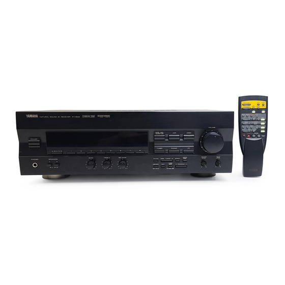
R- V702
R- V502
Natural Sound AV Receiver
Récepteur audiovisuel "Son Naturel"
Receptor AV de Sonido Natural
MANUAL DE INSTRUCCIONES
OWNER'S MANUAL
MODE D'EMPLOI
Advertisement
Table of Contents

Related Manuals for Yamaha R-V702 R-V502


Summary of Contents for Yamaha R-V702 R-V502
- Page 1 Thank you for selecting this YAMAHA AV receiver. Nous vous remercions d’avoir porté votre choix sur ce récepteur audiovisuel YAMAHA. Muchas gracias por haber adquirido este receptor AV YAMAHA. R- V702 R- V502 Natural Sound AV Receiver Récepteur audiovisuel “Son Naturel”...
-
Page 2: Safety Instructions
SAFETY INSTRUCTIONS CAUTION RISK OF ELECTRIC SHOCK DO NOT OPEN CAUTION: TO REDUCE THE RISK OF ELECTRIC SHOCK, DO NOT REMOVE COVER (OR BACK). NO USER-SERVICEABLE PARTS INSIDE. REFER SERVICING TO QUALIFIED SERVICE PERSONNEL. • Explanation of Graphical Symbols The lightning flash with arrowhead symbol, within an equilateral triangle, is intended to alert you to the presence of uninsulated “dangerous... - Page 3 This product, when installed as indicated in the instructions contained in this manual, meets FCC requirements. Modifications not expressly approved by Yamaha may void your authority, granted by the FCC, to use the product. 2. IMPORTANT : When connecting this product to accessories and/or another product use only high quality shielded cables.
-
Page 4: Table Of Contents
CONTENTS Safety Instructions ... Supplied Accessories ...2 Features ...3 Caution ...4 Notes about the Remote Control Transmitter ...5 Profile of This Unit ...6 Speaker Setup ...7 Connections ...8 Controls and Their Functions ...14 SUPPLIED ACCESSORIES After unpacking, check that the following parts are included. Indoor FM Antenna AM Loop Antenna Antenna adapter (U.S.A. -
Page 5: Features
Digital Sound Field Processor Dolby Pro Logic Surround Decoder > Theater-like Sound Experience by the Combination of Dolby Pro Logic and YAMAHA DSP Technology (CINEMA DSP) Automatic Input Balance Control for Dolby Pro Logic Surround > Test Tone Generator for Easier Speaker... -
Page 6: Caution
CAUTION : READ THIS BEFORE OPERATING YOUR UNIT. To assure the finest performance, please read this manual carefully. Keep it in a safe place for future reference. Install this unit in a cool, dry, clean place – away from windows, heat sources, sources of excessive vibration, dust, moisture and cold. -
Page 7: Notes About The Remote Control Transmitter
NOTES ABOUT THE REMOTE CONTROL TRANSMITTER Battery installation Battery replacement If you find that the remote control transmitter must be used closer to the main unit, the batteries are weak. Replace both batteries with new ones. Notes Use only AA, R6, UM-3 batteries for replacement. Be sure the polarities are correct. -
Page 8: Profile Of This Unit
You are the proud owner of a Yamaha stereo receiver –an extremely sophisticated audio component. The Digital Sound Field Processor (DSP) built into this unit takes advantage of Yamaha’s undisputed leadership in the field of digital audio processing to bring you a whole new world of listening experiences. Follow the instructions in this manual carefully when setting up your system, and this unit will sonically transform your room into a wide range of listening environments –movie theater, concert hall, and so on. -
Page 9: Speaker Setup
SPEAKERS TO BE USED This unit is designed to provide the best sound-field quality with a 5 speaker configuration. The most effective speakers to use with this unit are main speakers, rear speakers and a center speaker. You may omit the center speaker. (Refer to the “4-Speaker Configuration”... -
Page 10: Connections
L, R (right) to R, “+” to “+” and “–” to “–”. Also, refer to the owner’s manual for each component to be connected to this unit. * If you have YAMAHA components numbered as 1, 2, 3, etc. on the rear panel, connections can be made easily by making sure to connect the output (or input) terminals of each component to the same-numbered terminals of this unit. - Page 11 R-V502 Monitor TV Turntable VIDEO SIGNAL UNBAL. MONITOR OUT VIDEO PHONO TAPE TAPE VIDEO ( MD ) AUDIO SIGNAL Tape deck, MD recorder, etc. AC OUTLET(S) (SWITCHED) (U.S.A., Canada and General models) ... 2 SWITCHED OUTLETS (Australia model) ... 1 SWITCHED OUTLET Use these to connect the power cords from your components to this unit.
-
Page 12: Connecting Speakers
Connect the SUBWOOFER OUTPUT terminal of this unit to the INPUT terminal of the subwoofer amplifier, and connect the speaker terminals of the subwoofer amplifier to the subwoofer. With some subwoofers, including the Yamaha Active Servo Processing Subwoofer System, the amplifier and subwoofer are in the same unit. - Page 13 How to Connect: Connect the SPEAKERS terminals to your speakers with wire of the proper gauge, cut as short as possible. If the connections are faulty, no sound will be heard from the speakers. Make sure that the polarity of the speaker wires is correct, that is the + and – markings are observed.
-
Page 14: Impedance Selector Switch
OUTPUT terminals (for driving speakers with external amplifiers) OUTPUT CENTER WOOFER IMPEDANCE SELECTOR switch Be sure to switch this only when the power of this unit is turned off. Select the position whose requirements your speaker system meets. IMPEDANCE SELECTOR REAR 6 MIN./SPEAKER CENTER... -
Page 15: Antenna Connections
ANTENNA CONNECTIONS Each antenna should be connected to the designated terminals correctly, referring to the following diagram. Both AM and FM indoor antennas are included with this unit. In general, these antennas will probably provide sufficient signal strength. Nevertheless, a properly installed outdoor antenna will give clearer reception than an indoor one. If you experience poor reception quality, an outdoor antenna may result in improvement. -
Page 16: Controls And Their Functions
CONTROLS AND THEIR FUNCTIONS FRONT PANEL R-V702 NATURAL SOUND AV RECEIVER POWER A/B/C/D/E PHONES SPEAKERS R-V502 NATURAL SOUND AV RECEIVER POWER A/B/C/D/E PHONES SPEAKERS CINEMA DSP R–V702 BASS TREBLE BALANCE CINEMA DSP R–V502 BASS TREBLE BALANCE CONCERT MONO PRO LOGIC ENHANCED VIDEO MOVIE... - Page 17 POWER switch Press this switch to switch the power on. Press it again to switch the power off. Standby mode indicator (Except U.S.A. and Canada models) While the power is on, pressing the SYSTEM POWER OFF key on the remote control transmitter switches the unit to the standby mode.
- Page 18 MEMORY (MAN’L/AUTO FM) button When this button is pressed, the MEMORY indicator flashes for about 5 seconds. During this period, select a desired preset station number by pressing the corresponding preset station number selector button to enter the displayed station into the memory.
-
Page 19: Display Panel
DISPLAY PANEL PRESET MEMORY AUTO Multi-information display Displays various information, for example station frequency, preset station number and name of selected input source. STEREO indicator Lights up when an FM stereo broadcast with sufficient signal strength is received. Signal-level meter Indicates the signal level of the received station. - Page 20 The remote control transmitter provided with this unit is designed to control all the most commonly used functions of this unit. If the CD player and tape deck connected to this unit are YAMAHA components designed for remote control compatibility, then this remote control transmitter will also control various functions of each component.
- Page 21 For Control of This Unit DELAY/CENTER/REAR and TIME/LEVEL +/– keys R-V702 only Adjust the delay time (DELAY), the rear channel output level (REAR) and the center channel output level (CENTER). Select the item which you want to adjust by pressing the DELAY/CENTER/REAR key and adjust its time or level by pressing the TIME/LEVEL +/–...
-
Page 22: Speaker Balance Adjustment
SPEAKER BALANCE ADJUSTMENT This procedure lets you adjust the sound output level balance between the main, center, and rear speakers using the built-in test tone generator. When this adjustment is performed, the sound output level heard at the listening position will be the same from each speaker. - Page 23 Select the center channel output mode suitable for your speaker configuration. (Refer to “SPEAKER CONFIGURATION” on page 7.) CENTER NORMAL MODE WIDE PHANTOM On the feature of each mode, refer to the “Note” shown below. Note In step 6, when you select a center channel output mode, note the following.
- Page 24 R-V702 TIME/ DELAY/CENTER – LEVEL /REAR TEST EFFECT ON/OFF PROGRAM PROLOGIC ENHANCED TV/DBS DVD/LD DIR A DIR B REC/PAUSE PLAY TAPE – A/B/C/D/E TUNER PRESET PLAY DISC PHONO POWER VOLUME SLEEP Adjust the sound output levels of the center speaker and the rear speakers so that they become almost as same as that of the main speakers.
-
Page 25: Basic Operations
TO PLAY A SOURCE VOLUME –dB ∞ Set to the “ ” position. Turn the power on. POWER Select the desired input source by using the input selector buttons. (For video sources, turn the TV/monitor ON.) TUNER PHONO * The name of the selected input source will appear on the display. -
Page 26: To Record A Source To Tape (Or Md)
TO RECORD A SOURCE TO TAPE (OR MD) R-V702 Select the source to be recorded. TUNER PHONO Play the source and then turn the VOLUME control up to confirm the input source. (For detailed information on the tuning operations, refer to the page 26.) VOLUME –dB R-V502... -
Page 27: Selecting The Speaker System
Selecting the SPEAKER system Because one or two speaker systems (as main speakers) can be connected to this unit, the SPEAKERS switches allow you to select speaker system A or B, or both at once. SPEAKERS Adjusting the BALANCE control Adjust the balance of the output volume to the left and right speakers to compensate for sound imbalance caused by speaker location or listening room conditions. -
Page 28: Tuning Operations
Normally, if station signals are strong and there is no interference, quick automatic-search tuning (AUTOMATIC TUNING) is possible. However, if signals of the station you want to select are weak, you must tune to it manually (MANUAL TUNING). AUTOMATIC TUNING Select the reception band (FM or AM) confirming it on the display. -
Page 29: Preset Tuning
MANUAL PRESET TUNING This unit can store station frequencies selected by tuning operation. With this function, you can recall any desired station by only selecting the preset station number where it is stored. Up to 40 stations (8 stations x 5 groups) can be stored. To store stations Tune to a desired station. -
Page 30: Automatic Preset Tuning
AUTOMATIC PRESET TUNING You can also make use of an automatic preset tuning function for FM stations only. By this function, this unit performs automatic tuning and stores FM stations with strong signals sequentially. Up to 40 stations are stored automatically in the same way as in the manual preset tuning method on page 27. -
Page 31: Exchanging Preset Stations
EXCHANGING PRESET STATIONS You can exchange the places of two preset stations with each other as shown below. Example) If you want to shift the preset station on E1 to A5, and vice versa. Recall the preset station on E1 (by following the method of “To recall a preset station”... -
Page 32: Using Digital Sound Field Processor (Dsp)
Dolby Surround. The operation of the Dolby Pro Logic Surround decoder can be controlled by selecting a corresponding DSP program including a combined operation of the Yamaha DSP and the Dolby Pro Logic Surround. Brief Overview of Digital Sound Field Programs The following list gives you a brief description of the sound fields produced by each of the DSP programs. -
Page 33: To Play A Source With The Digital Sound Field Processor
To play a source with the digital sound field processor R-V702 TIME/ – LEVEL PROGRAM DIR A DIR B REC/PAUSE –dB – PRESET POWER SLEEP Follow steps 1 – 6 shown in “BASIC OPERATIONS” on page 23. Select the desired program that is suitable for the source. -
Page 34: Adjustment Of The Center Level
Adjustment of the CENTER LEVEL If desired, you can adjust the sound output level of the center speaker even if the output level is already set in “SPEAKER BALANCE ADJUSTMENT” on page 22. R-V702 Press once or more so that “CENTER” appears on the display. -
Page 35: Adjustment Of Delay Time
Adjustment of DELAY TIME You can adjust the time difference between the beginning of the sound from the main speakers and the beginning of the effect sound from the rear speakers. The larger the value, the later the effect sound is generated. This adjustment can be made to all programs individually. -
Page 36: Setting The Sleep Timer
SETTING THE SLEEP TIMER If you use the SLEEP timer of this unit, you can make this unit turn off automatically. When you are going to sleep while enjoying a broadcast or other desired input source, this timer function is helpful. Notes The SLEEP timer can be controlled only with the remote control transmitter. -
Page 37: Troubleshooting
If the unit fails to operate normally, check the following points to determine whether the fault can be corrected by the simple measures suggested. If it cannot be corrected, or if the fault is not listed in the SYMPTOM column, disconnect the power cord and contact your authorized YAMAHA dealer or service center for help. SYMPTOM... -
Page 38: Specifications
SPECIFICATIONS AUDIO SECTION Minimum RMS Output Power per Channel Main L, R 8 ohms, 1 kHz, 0.09% THD < > R-V702 ...80W + 80W < > R-V502 [U.S.A. model]...70W + 70W [Australia Canada and General models] ...60W + 60W Center 8 ohms, 1 kHz, 0.09% THD <... - Page 39 Alternate Channel Selectivity [U.S.A., Canada and General models] ...85 dB Selectivity (two signals, 40 kHz Dev. ±300 kHz) [Australia model] ...70 dB Signal-to-Noise Ratio (IHF) Mono/Stereo [U.S.A., Canada and General models] ...80 dB/75 dB (DIN-Weighted, 40 kHz Dev.) Mono/Stereo [Australia models] ...75 dB/70 dB Harmonic Distortion Mono/Stereo (1 kHz) ...0.1/0.2% Stereo Separation (1 kHz)...50 dB...
- Page 40 YAMAHA ELECTRONICS (UK) LTD. YAMAHA HOUSE, 200 RICKMANSWORTH ROAD WATFORD, HERTS WD1 7JS, ENGLAND YAMAHA SCANDINAVIA A.B. J A WETTERGRENS GATA 1, BOX 30053, 400 43 VÄSTRA FRÖLUNDA, SWEDEN YAMAHA MUSIC AUSTRALIA PTY, LTD. 17-33 MARKET ST., SOUTH MELBOURNE, 3205 VIC., AUSTRALIA...