
Related Manuals for Nanni N16.900 CR3


Summary of Contents for Nanni N16.900 CR3
- Page 1 NANNI MARINE ENGINE OPERATOR MANUAL DGBXXT09019 ENGINE N16.900 CR3 N16.1000 CR3 N16.1100 CR3 N16.1150 CR3 N16.1200 CR3...
-
Page 3: Q00 Tracked Changes
TRACKED CHANGES TRACKED CHANGES CODE INDEX DATE INITIALS NATURE OF TRANSLATIONS PAGES DGBXXT09019 08/2020 LB-MC Create Please note all changes and pages associated. For further clarity, please add a line in front of each change. -
Page 5: Table Of Contents
SUMMARY Table des matières ENGINE LUBRICANTS TRACKED CHANGES FUELS TRACKED CHANGES SUMMARY INTRODUCTION WATER IN FUEL INTRODUCTION S04 ENGINE WARRANTY ABOUT THIS MANUAL ENGINE IDENTIFICATION CONTENT & UPDATES ORIGINAL SUPPLIER ENGINE PLATE S02 SAFETY ENGINE HOMOLOGATION SUMMARY ENGINE RESPONSABILITY SAFETY SIGNALS WARRANTY SAFETY INFORMATION PROPOSITION 65 STATE OF CALIFORNIA... - Page 6 SUMMARY CRUISING SPEED LITRE MARINE ENGINE WITH XPI MANOEUVRING RENEWING THE FUEL FILTER TROLLING VALVE VENTING THE FUEL FILTER AFTER RUNNING CHECKING THE DRIVE BELT STOPPING THE ENGINE GENERAL TIGHTENING TORQUES FOR SCREWS AFTER STOPPING THE ENGINE JOINTS ANCHORING STORAGE COLD WEATHER PRECAUTIONS SUMMARY S08 MAINTENANCE...
-
Page 7: S01 Introduction
If there are any equipment details that are not shown or described in this Manual, or if you have any question regarding the operation of any equipment, your authorized Nanni dealer will be glad to inform you of correct care and operating procedures. -
Page 8: About This Manual
Please ensure that this Manual is always kept in the authorized Nanni Dealer will be glad to inform you of boat. It should always be available to anyone else using correct care and operating procedures. -
Page 9: S02 Safety
SAFETY SUMMARY Table des matières SAFETY SUMMARY SAFETY SIGNALS SAFETY INFORMATION REPLACEMENT OF MISSING OR DAMAGED SAFETY SIGNS READ SAFETY INSTRUCTIONS ENGINE-GENSET SAFETY ICONS SAFETY PRECAUTIONS HOT EXHAUST PRECAUTIONS WORK IN VENTILATED AREA WASTE DISPOSAL UNWANTED ENGINE START SAFE MAINTENANCE PRACTICE WORK IN CLEAN AREA PROTECTIVE CLOTHING SERVICE ENGINES SAFELY... -
Page 10: Safety Signals
Carefully read all safety messages in this manual and on If you do not understand any part your genset safety signs. of this document and need assistance, contact your Nanni Keep safety signs in good condition. Be sure new representative. equipment components and repair parts include the current safety signs. -
Page 11: Engine-Genset Safety Icons
SAFETY ENGINE-GENSET SAFETY ICONS Indicates the oil drain orifice. Some stickers are fixed directly on the engine. They are intended to help you to quickly identify the location of certain components and avoid possible hazards when working on the engine. Ensure that these stickers are always visible and replace them if torn or washed up. -
Page 12: Safety Precautions
SAFETY SAFETY PRECAUTIONS UNWANTED ENGINE START Avoid possible injury or death from engine runaway. Do not start engine by shorting HOT EXHAUST PRECAUTIONS across starter motor solenoid terminals posts. Engine will start if normal Servicing machine or attachments with circuitry is bypassed. Start engine from engine running can result in serious operator’s seat. -
Page 13: Service Engines Safely
SAFETY SERVICE ENGINES SAFELY PROPER LIFTING EQUIPMENT Tie long hair behind your head. Do not wear a necktie, scarf, loose clothing, or necklace when you work near moving parts. If these items were to get caught, severe injury could result. Remove rings Lifting heavy components incorrectly can cause severe and other jewelry to prevent electrical injury or equipment damage. -
Page 14: Staying Clear Of Rotating Drivelines
SAFETY STAYING CLEAR OF ROTATING Common Rail (HPCR) fuel system. Only technicians familiar with this type of system can perform repairs. DRIVELINES Consult your engine representative. Entanglement in rotating driveline can cause serious injury or death. Keep all AVOID HIGH-PRESSURE FLUIDS shields in place at all times. -
Page 15: Welding Near Electronic Control Unit (Ecu)
SAFETY WELDING NEAR ELECTRONIC CONTROL HANDLE FUEL SAFELY - AVOID FIRES UNIT (ECU) Handle fuel with care: it is highly flammable. Do not refuel the engine while smoking or when near open flame If welding is required around the engine, or or sparks.Always stop engine before refueling. -
Page 16: Prevent Battery Explosions
SAFETY Always remove grounded (-) battery clamp first and replace grounded clamp last. Sulfuric acid in battery WARNING ! electrolyte is poisonous and strong enough to burn skin, eat holes in clothing, and cause blindness if splashed into eyes. Battery posts, terminals, and related accessories contain Avoid hazards and acid burns in : lead and lead compounds. -
Page 17: S03 Fluids
FLUIDS SUMMARY FLUIDS SUMMARY COOLANT WATER ADDITION OF ANTIFREEZE & CORROSION INHIBITOR TO WATER RISK OF FREEZING HOT CLIMATES TOPPING UP RECOMMENDED COOLANT ANTIFREEZE & CORROSION PROTECTION ANTIFREEZE & CORROSION PROTECTION CHECKING THE COOLANT LEVEL CHECKING THE COOLANT’S ANTIFREEZE & CORROSION PROTECTION ENGINE LUBRICANTS OIL GRADE DENOMINATION OIL GRADE LABELS... -
Page 18: Coolant
This can lead to the invalidation of Nanni’s warran- the cooling system. This can lead to the invalidation of ty for faults and damage caused by the use of inappro- Scania’s warranty for faults and damage caused by the... -
Page 19: Risk Of Freezing
FLUIDS RISK OF FREEZING Example: If the temperature is -16 C (3°F), there is a risk of dam- age by freezing if the percentage of antifreeze and cor- rosion inhibitor is 20% by volume. At 30% antifreeze and IMPORTANT ! corrosion protection by volume the coolant will not con- tain any ice. -
Page 20: Recommended Coolant
FLUIDS RECOMMENDED COOLANT IMPORTANT ! Scania Ready-Mix 50/50 Scania Ready-Mix 50/50 is a ready to use coolant con- taining 50 % antifreeze (ethylene glycol) and corrosion Containers, which are used for mixing coolant, must be protection and 50 % water. It should be used in cold intended for the purpose and free from any dirt or con- countries where there is a risk of freezing in the cooling taminants. -
Page 21: Antifreeze & Corrosion Protection
FLUIDS ANTIFREEZE & CORROSION PROTECTION TABLE in LITRES & °C 35% by volume of antifreeze provides sufficient protec- tion against corrosion. Example: • The total volume of the cooling system is 40 litres. • The measured concentration of ethylene glycol is 35% by volume (freezing point -21°C). -
Page 22: Antifreeze & Corrosion Protection
FLUIDS ANTIFREEZE & CORROSION PROTECTION TABLE in U.S GALLONS & °F 35% by volume of antifreeze provides sufficient protec- tion against corrosion. Example: • The total volume of the cooling system is 10.6 U.S gal- lons. • The measured concentration of ethylene glycol is 35% by volume (freezing point -6 °F). -
Page 23: Checking The Coolant Level
FLUIDS CHECKING THE COOLANT LEVEL CHECKING THE COOLANT’S ANTIFREEZE & CORROSION PROTECTION Specific tool WARNING ! Description Illustration Refractometer Do not open the coolant filler cap in the expan-sion tank if the engine is hot. Hot coolant and steam may spray out and cause burns. -
Page 24: Engine Lubricants
FLUIDS ENGINE LUBRICANTS For operation at extremely low outdoor temperatures: Consult your nearest Nanni representative on how to avoid starting difficulties. OIL GRADE DENOMINATION Viscosity Outdoor temperatures in °C class LDF branded oil stands for the Scania Long Drain Field SAE 20W-30 -15°C... -
Page 25: Oil Grade Labels
If the oil grades below are used, you can order oil filler • TBN (in accordance with ASTM D4739): > 3.5. labels from your Nanni representative. • TBN (in accordance with ASTM D4739): > TAN (in accordance with ASTM D664). -
Page 26: Fuels
FLUIDS FUELS PERMITTED SULPHUR CONTENT IN DIESEL IMPORTANT ! DANGER ! The operator is responsible for using the correct type of Fuels and some fluids on board ships are easily flam- diesel to ensure that local laws are complied with. mable. -
Page 27: Hvo
Check the engine oil level regularly. If the oil level ex- ceeds the maximum level, the oil must be changed. Check the cause if the oil level exceeds the maximum level and contact your nearest Nanni representative if you suspect a fault, or in case of doubt. -
Page 28: Water In Fuel
PRESERVATIVE FUEL injection system and cause a total engine failure which is not covered by Nanni Industries warranty. In the event Preservative fuel must not contain biodiesel. Even small of fuel contamination, contact the nearest Nanni agent amounts of 5-10% biodiesel can have adverse effects who may, if necessary, use an approved disinfectant. -
Page 29: S04 Engine Warranty
2 : Engine number 3 : Engine code Both the engine and the transmission have an 4 : Nanni number identification plate containing important informations. Keep these plates accessible and in good condition. Record and keep the engine and transmission serial ORIGINAL SUPPLIER ENGINE PLATE number and designation. -
Page 30: Engine Homologation
This manual is supplemented by a Warranty Information The engine type can be exhaust emission certified. It means that Nanni guarantees that all engines of the Booklet. We recommend that you read this publication same type that are manufactured are approved and thoroughly. -
Page 31: Proposition 65 State Of California
Directive 2004/26/EC. The EU engine family is listed on the Emissions Label. When installed in accordance with the manufacturer’s instructions, Nanni Industries Marine Diesel Propul- sion Engines without integral exhaust certified under Directive 97/68/EC as amended by Directive 2004/26/... -
Page 32: S05 Components
COMPONENTS SUMMARY Table des matières COMPONENTS SUMMARY ENGINE MAIN COMPONENTS ENGINE VIEWS N16 CR3... -
Page 33: Engine Main Components
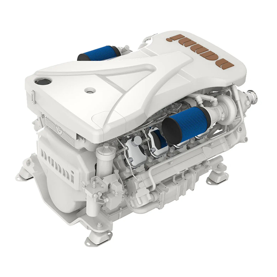
COMPONENTS ENGINE MAIN COMPONENTS NOTE ! Minor engine details may not be exactly as shown. Some components may not be part of the engine ordered. Not binding pictures. COMPONENTS Oil filter Air filter Sacrificial anodes (6 off) Sea water pump Sea water outlet intake Sea water outlet (1 on each side) Valve for draining anf filling coolant (1 on each side behind the heat exchanger) -
Page 34: Engine Views N16 Cr3
COMPONENTS ENGINE VIEWS N16 CR3... - Page 35 NOTES...
-
Page 36: S06 Instrumentation Summary
INSTRUMENTATION SUMMARY TABLE DES MATIÈRES INSTRUMENTATION SUMMARY INTRODUCTION PRODUCT IDENTIFICATION FRONT SIDE PRESENTATION START BUTTON NAVIGATION SCROLL BUTTON (HIDE) NAVIGATION SCROLL BUTTON STOP BUTTON (MUTE) ELECTRICAL CONNECTIONS DISPLAYED DATA SAFEGUARD FUNCTION FAULT CODES SYSTEM LAYOUT INCLUDING OPTIONS... -
Page 37: Introduction
INSTRUMENTATION INTRODUCTION This chapter is intended for professionals and seasoned technicians. Users of this equipment are assumed to be fluent in handling marine systems, and must be able to carry out related electrical tasks. This chapter describes the features of the unit, the use and specifications. Including software embedded, the SI.3 is a 3.5”... - Page 38 INSTRUMENTATION REAR SIDE DIMENSIONS & WEIGHT The rugged unit is made of thermoplastic polymer compound (PBT), impact resistant and flame retarded. Item Description Dimensions 119,9 (W) x 79,6 (H) x 49 (D), in mm Weight 0,250 kg Spacing threads 48,5 mm Threads dimension M5 Threads depth 7,7 mm...
-
Page 39: Electrical Connections
INSTRUMENTATION ELECTRICAL CONNECTIONS Bracket (RAM) mount : Once the SI.3 has been fitted in place, connections must be made. The harness is a plug and play system and is delivered with relevant poka-yoke connectors for trou- blefree connection to the Engine Control Box. To this purpose, a cable extension may be required. -
Page 40: Displayed Data
INSTRUMENTATION DISPLAYED DATA 4. The display returns to normal operation and, after a delay, the pop up fault will come back if fault has not been resolved in the mean time. After powering, and after SI.3 booting, the normal se- 5. -
Page 41: Fault Codes
INSTRUMENTATION FAULT CODES Fault codes generated in the CAN network are sent via CAN message DM1. This document describes how to interpret these fault codes from the DM1 message. Abbreviations used FMI = Fault Mode Identifier SPN = Suspected Parameter Number OC = Over Crank _ Number of faults occurances Explanation table of FMI codes Code... - Page 42 INSTRUMENTATION Explanation table of SPN codes SPN SPN Name SPN Description Pneumatic Supply Pressure Pneumatic pressure in the main reservoir, sometimes referred to as the wet tank. Position of the valve used to regulate the supply of a fluid, usually air or fuel/air Engine Throttle Valve 1 Position mixture, to an engine.
- Page 43 INSTRUMENTATION SPN SPN Name SPN Description Engine Speed At High Idle, Point 6 Engine speed of high idle of the engine torque map. (Engine Configuration) Switch signal which indicates whether the accelerator pedal kickdown switch is Accelerator Pedal 1 Low Idle Switch opened or closed.
- Page 44 INSTRUMENTATION SPN SPN Name SPN Description 1323 Engine Misfire Cylinder #1 Engine misfire detected in cylinder. 1324 Engine Misfire Cylinder #2 Engine misfire detected in cylinder. 1325 Engine Misfire Cylinder #3 Engine misfire detected in cylinder. 1326 Engine Misfire Cylinder #4 Engine misfire detected in cylinder.
- Page 45 INSTRUMENTATION SPN SPN Name SPN Description The amount of combined NO and NO2 in the exhaust entering the aftertreatment 3216 Aftertreatment 1 Intake NOx system measured by a NOx sensor at the aftertreatment intake, represented in NOx molecule parts per million non-NOx molecules in exhaust bank 1. The amount of combined NO and NO2 in the exhaust entering the aftertreatment 3226 Aftertreatment 1 Outlet NOx system measured by a NOx sensor at the aftertreatment outlet, represented in...
- Page 46 INSTRUMENTATION SPN SPN Name SPN Description Aftertreatment 1 Diesel Exhaust Fluid 3516 A measure of the concentration of urea in water. Concentration Engine Intake Manifold #1 Absolute 3563 The absolute pressure measurement of the air intake manifold. Pressure A signal issued by the engine control system to a user or external system 3606 Engine Controlled Shutdown Request requesting for a controlled shutdown.
- Page 47 INSTRUMENTATION SPN SPN Name SPN Description Aftertreatment 2 Diesel Exhaust Fluid 4427 Temperature of the diesel exhaust fluid in the storage tank. Tank Temperature Diesel Particulate Filter 1 Soot 4782 Soot density in diesel particulate filter 1. Density Aftertreatment 1 Warm Up Diesel The temperature measured at the intake of the warm up oxidation catalytic 4809 Oxidation Catalyst Intake temperature...
-
Page 48: System Layout Including Options
INSTRUMENTATION SYSTEM LAYOUT INCLUDING OPTIONS... -
Page 49: S07 Starting & Running
STARTING & RUNNING SUMMARY Table des matières STARTING & RUNNING SUMMARY BEFORE STARTING FUEL SYSTEM RAW WATER SYSTEM NEUTRAL SAFEGUARD CHECKS BEFORE STARTING STARTING THE ENGINE COLD WEATHER OPERATION ENGINE START IGNITION AND CRANKING ENGINE STARTED STARTING WITH BOOSTER BATTERIES ENGINE RELUCTANT TO START IDLING ENGINE NORMAL ENGINE OPERATION... -
Page 50: Before Starting
STARTING & RUNNING BEFORE STARTING NOTE ! FUEL SYSTEM The use of a siphon breaker is mandatory if the exhaust The fuel is drawn from the tank by the fuel feed pump elbow is under the waterline at full load or at less than and is injected into the combustion chamber by the 200 mm above it. -
Page 51: Checks Before Starting
Turn on the engine coolant heater for a minimum of 2 required. hours before starting the engine. Additional information on cold weather operation is available from your Nanni 9. Check there are no fuel, oil, coolant or water leaks. engine distributor or authorized servicing dealer. -
Page 52: Engine Start
STARTING & RUNNING ENGINE START ENGINE STARTED In the wheelhouse, turn the Key switch to energize the To insure adequate lubrication, operate engine at or electronic system. below 1200 rpm with no load for 1-2 minutes. Extend this period to 2–4 minutes at freezing or sub-zero temperatures. -
Page 53: Engine Reluctant To Start
STARTING & RUNNING ENGINE RELUCTANT TO START NORMAL ENGINE OPERATION Check engine coolant temperature and oil pressure. If a water lift (water lock) muffler is installed on the exhaust line, excessive cranking could cause seawater Temperatures and pressures will vary between engines and with changing operating conditions, temperatures, to enter the cylinders and damage the engine. -
Page 54: Break In
The use of a PTO should always be studied and approved by Consult the boat builder or your Nanni dealer if you are the R&D department of Nanni Industries S.A.S France. not sure about the operation of the remote control. -
Page 55: Running
STARTING & RUNNING RUNNING CRUISING SPEED A recommended engine speed is given in the TECHNICAL BEHAVIOUR OF THE BOAT DATA section to help you to set your cruising speed. If this is your first boat or if you are not familiar with the boat, we urge you to practice controlling the boat at NOTE ! slow speed as a first step. -
Page 56: Manoeuvring
STARTING & RUNNING MANOEUVRING TROLLING VALVE The Trolling valve system allows to reduce the rotation speed of the propeller below its speed when the engine is WARNING ! at idle. The boat speed is reduced by 30% to 70%. Shifting at high speed can damage both the engine and CAUTION ! the transmission and be dangerous for passengers. -
Page 57: After Running
STARTING & RUNNING AFTER RUNNING AFTER STOPPING THE ENGINE STOPPING THE ENGINE CAUTION ! Even after the engine has stopped, some components CAUTION ! and fluids will remain hot and under pressure for several minutes. As far as possible, limit works on the engine Never stop the engine by using the main switch. -
Page 58: Anchoring
STARTING & RUNNING ANCHORING If the boat is not going to be used for some time but is being left in the water, the engine must be run to operating temperature at least once every 2 weeks. This prevents corrosion in the engine. When the boat is at anchor or in port for an extended period of time, vegetation may develop on the hull, the keel, the drive, the rudder, the propeller, etc. -
Page 59: S08 Maintenance
MAINTENANCE SUMMARY Table des matières MAINTENANCE SUMMARY ABOUT GENERALITIES MAINTENANCE MAINTENANCE INTERVALS TURBOCHARGER TURBOSERVICE LUBRICATION SYSTEM OILS CHECKING THE OIL LEVEL CHANGING THE OIL MAXIMUM ANGLES OF INCLINATION DURING OPERATION CLEANING THE CENTRIFUGAL OIL CLEANER OPERATIONAL TESTING OF THE CENTRIFUGAL OIL CLEANER RENEWING THE OIL FILTER AIR CLEANER REPLACE THE AIR CLEANER FILTER AND SAFETY CARTRIDGE... -
Page 60: About
During the warranty period, it is essential to get any work carried out by a Nanni authorized workshop. Furthermore, any service should be registered in the Nanni after-sale system. -
Page 61: Generalities
MAINTENANCE GENERALITIES MAINTENANCE The maintenance scheddule covers a number of points WARNING ! divided into several sections : • Lubrication system. Perform maintenance operations having the engine • Air cleaner stopped and cold. Get the the starting key out from the •... -
Page 62: Maintenance Intervals
MAINTENANCE MAINTENANCE INTERVALS The maintenance program includes the following : • R maintenance : one event when taken into service • S maintenance : minimum basic maintenance • M maintenance : more extensive maintenance • L maintenance : includes nearly all maintenance items in the form •... -
Page 63: Turbocharger
MAINTENANCE TURBOCHARGER TURBOSERVICE Engine turbochargers are designed to provide long years of trouble free service, which if re- CAUTION ! quired, can only be performed by a specialized workshop. In view to maintain turbochargers performances for as long as possible, some A turbocharger is an exhaust-driven mechanical device basic rules must be followed. -
Page 64: Lubrication System
MAINTENANCE LUBRICATION SYSTEM CHANGING THE OIL OILS NOTE ! Change oil more often if the engine is subjected to par- NOTE ! ticularly demanding operation, such as a dusty envi- ronment, or if deposits in the centrifugal oil cleaner are thicker than 28 mm (1.1 in). -
Page 65: Maximum Angles Of Inclination During Operation
MAINTENANCE MAXIMUM ANGLES OF INCLINATION DURING OPERATION Maximum permissible angles of inclination during oper- ation vary, depending on the type of oil sump. See illus- tration below: 6. If the rotor nut is jammed: Turn the rotor upside down and fasten the rotor nut in a vice. 7. - Page 66 MAINTENANCE 14. Remove the paper insert. 20. Fit the strainer onto the rotor. 15. Scrape off any remaining dirt deposits from the 21. Fit a new O-ring to the foot of the centrifugal oil inside of the rotor cover. If the deposits on the paper are cleaner.
-
Page 67: Operational Testing Of The Centrifugal Oil Cleaner
MAINTENANCE OPERATIONAL TESTING 26. Fit a new O-ring in the cover. 27. Refit the cover and tighten the lock nut.Tightening OF THE CENTRIFUGAL OIL torque is of 20 Nm (15 lb-ft). CLEANER IMPORTANT ! Operational testing need only be carried out if it is suspected that the centrifugal oil cleaner is To reduce the risk of oil leakage it is important to tighten malfunctioning. -
Page 68: Renewing The Oil Filter
MAINTENANCE RENEWING THE OIL FILTER Tools required Designation Illustration Hexagon socket, 1/2”, 36 mm IMPORTANT ! Clean the centrifugal oil cleaner at the same time as you change the oil filter. Otherwise, the oil filter will become blocked and the resistance in the filter will increase. If this happens, an overflow valve in the filter retainer opens and lets the oil pass without being filtered. -
Page 69: Air Cleaner
MAINTENANCE AIR CLEANER Reading the vacuum indicator If the indicator’s red plunger is fully visible, renew the air cleaner filter element following the instructions below. Renewing the filter element WARNING ! Renewing the safety cartridge Never start the engine without the air filter in position. WARNING ! If you do this, you risk personal injury and severe engine damage. -
Page 70: Replace The Air Cleaner Filter And Safety Cartridge
MAINTENANCE COOLING SYSTEM Renewing an air filter with a non-renewable element IMPORTANT ! WARNING ! If the engine has air filters with a non-renewable Scania Ethylene glycol can be fatal if ingested and can cause element, they should be renewed instead of cleaned. skin irritation and eye damage. -
Page 71: Checking The Coolant Level
MAINTENANCE CHECKING THE COOLANT CHECKING THE COOLANT LEVEL ANTI FREEZE AND CORROSION PROTECTION WARNING ! Tools required Designation Illustration Do not open the coolant filler cap in the expansion tank if the engine is hot. Hot coolant and steam may spray out and cause burns. -
Page 72: Checking The Sacrificial Anodes
MAINTENANCE CHECKING THE Renewing the sea water pump impeller SACRIFICIAL ANODES Special tool required Number Designation Illustration 1. Drain the sea water circuit. See the section Draining the sea water circuit. 2 443 680 Puller 2. Check the sacrificial anodes and scrape off all loose material from them. -
Page 73: Checking The Sea Water Pump Impeller
MAINTENANCE IMPORTANT ! WARNING ! Do not open the coolant filler cap in the expansion tank if Check that the direction of rotation of the impeller vanes the engine is hot. Hot coolant and steam may spray out is the same as during removal. and cause burns. -
Page 74: Draining The Sea Water Pump Impeller
MAINTENANCE DRAINING THE SEA WATER REMOVING THE CHARGE PUMP IMPELLER AIR COOLER 1. Close the bottom valve on the sea water inlet and re- When the charge air cooler core needs cleaning, the move the connection pipe on the outlet from heat ex- charge air cooler must be removed if there is no space changer (1). -
Page 75: Cleaning The Charge Air Cooler
MAINTENANCE 5. Remove all sea water pipes to and from the charge air 9. Lift out the charge air cooler: cooler. CLEANING THE CHARGE AIR COOLER 6. Right-hand turbocharger: Remove the Vclamp and the screw for the bracket. Remove the charge air pipe. The charge air cooler must be removed if there is no 7. -
Page 76: Removing The Heat Exchanger
MAINTENANCE REMOVING THE HEAT 2. Remove the screws on the charge air cooler covers (1) and remove the covers. Mark the covers so that you can EXCHANGER put them back on the correct side. 3. Press in the cooler core (5) slightly on one side and When the heat exchanger core needs cleaning, the heat pull it out from the other side. -
Page 77: Cleaning The Heat Exchanger
MAINTENANCE CLEANING THE HEAT 5. Remove the coolant pipe from the heat exchanger: EXCHANGER 1. Remove the screws on the heat exchanger covers (1) and remove the covers. Mark the covers so that you can put them back on the correct side. 2. -
Page 78: Fitting The Heat Exchanger
MAINTENANCE FITTING THE HEAT 5. Fit the sea water pipe between the charge air cooler and heat exchanger. EXCHANGER 1. Fit the heat exchanger by holding the bracket for the exhaust manifold, moving it slightly to the side and fit- ting it: 6. -
Page 79: Fitting The Charge Air Cooler
MAINTENANCE FITTING THE CHARGE AIR 5. Fit the charge air pipe and the hose clamps: COOLER 1. Fit the charge air cooler. Tighten the 4 screws to 50 Nm (37 lb-ft): 6. Fit the crankcase ventilation hose: 2. Carefully fit the charge air pipe from the lefthand tur- bocharger and tighten the V-clamp to 20 Nm (15 lb-ft). - Page 80 MAINTENANCE Internal: Removing oil and grease 8. Drain the water from the cooling system. 9. If necessary, clean the expansion tank by detaching all hoses and rinsing and cleaning with a degreasing ENVIRONMENT agent and a dish brush. Alternatively, dismantle the expansion tank and clean it Use a suitable container.
-
Page 81: Filling Coolant
MAINTENANCE FILLING COOLANT 1. Open the expansion tank cap. 2. Connect the coolant pump to the filler nipple in the This procedure applies when the cooling system has cylinder block. been drained and needs to be filled with a large amount of coolant. -
Page 82: Fuel System
MAINTENANCE FUEL SYSTEM DRAINING AND RENEWING THE DUAL WATER Cleanliness requirements SEPARATING PREFILTER IMPORTANT ! IMPORTANT ! The whole fuel system is very sensitive to dirt and also very small particles. Foreign particles in the system can The sensor cable is sensitive. Handle it carefully. cause serious malfunctions. -
Page 83: Draining And Renewing The Single Water Separating Prefilter
MAINTENANCE DRAINING AND RENEWING THE SINGLE WATER SEPARATING PREFILTER IMPORTANT ! The sensor cable is sensitive. Handle it carefully. ENVIRONMENT Legend: 1. Sensor cable. Use a suitable container. The fuel collected must be dis- 2. Drain tap. posed of as specified in national and international laws 3. -
Page 84: Renewing The Reversible Water Separating
MAINTENANCE RENEWING THE REVERSIBLE 1. Switch off the filter that needs renewing. The arrow on the rotary control points towards the filter in op- WATER SEPARATING eration. PREFILTER WARNING ! During operation, the arrow on the rotary control should point towards the filter being used. Be careful that the valve does not pass the closed posi- tion when the engine is in operation. -
Page 85: Renewing The Commutative Fuel Filter, 16 Litre Marine Engine With Xpi
MAINTENANCE RENEWING THE COMMUTA- 4. Remove the filter and fit the new filter. TIVE FUEL FILTER, 16 LITRE MARINE ENGINE WITH XPI Tools required Number Description 2 002 537 Grease for O-ring 5. Renew the O-rings in the cover. ENVIRONMENT 6. -
Page 86: Renewing The Fuel Filter
MAINTENANCE VENTING THE FUEL FILTER VENTING THE FUEL SYSTEM USING A HAND PUMP ENVIRONMENT Use a suitable container. The fuel collected must be dis- posed of as specified in national and international laws and regulations. 1. Screw up the hand pump handle (1). 2. - Page 87 1. Turn the rotary control so that it is pointing towards filter B. The fuel will then flow through the filter: NOTE ! Nanni recommends bleeding the fuel system using suction tools rather than with a hand pump. This is a quicker and simpler method, which ensures a complete bleeding.
-
Page 88: Checking The Drive Belt
MAINTENANCE MISCELLANEOUS 5. Close the bleed nipple on the fuel filter. Tightening torque 9 Nm. 6. Attach a clear plastic hose to the bleed nipple on the CHECKING THE DRIVE BELT high pressure pump (3). Let the plastic hose drop into a container that holds at least 5 litres (1.3 US gallons). - Page 89 3. Check drive belt wear. Renew the drive belt if it is too worn. See the illustrations below: IMPORTANT ! If serious leakage occurs, contact your nearest Nanni- representative. 1. Start the engine. 2. Check for leaks in the lubrication, intake, cooling, fuel, or exhaust system.
- Page 90 MAINTENANCE CHECKING AND ADJUSTING The reference information UP TDC,DOWN TDC and the angle indications listed in the table below are engraved VALVE CLEARANCE on the flywheel. Depending on the engine installation and type of flywheel housing, this information is visible in one of the windows, either furthest up or furthest Tools required down on the flywheel.
- Page 91 MAINTENANCE 1. Clean the rocker covers and the area around them. 2. Remove the rocker covers. 3. In order to rotate the flywheel, use a turning tool compatible with the installation of the engine, i.e. whether access is from above or from underneath. Use any specified special tool or the equivalent from another supplier.
-
Page 92: General Tightening Torques For Screws Joints
MAINTENANCE GENERAL TIGHTENING Hose clamps TORQUES FOR SCREWS Specifications in the tables show tightening torque when tightening by hand. JOINTS TIGHTENING TORQUE A= WIDTH Hexagon screws, hexagon socket screws, Torx screws, (mm) LB-FT hexagon nuts 7.5-9 Metric thread. Strength class 8.8/8. TIGHTENING TORQUE THREAD Lb-ft... - Page 93 STORAGE SUMMARY Table des matières STORAGE 93 SUMMARY LONG TERM STORAGE PREPARATIONS FOR STORAGE LONG TERM STORAGE PROCEDURE PRESERVATIVE PRODUCTS PRESERVATIVE COOLANT PRESERVATIVE FUEL RESTARTING THE ENGINE BATTERY...
- Page 94 For a prolonged storage (over 12 months), a specific set any means that the impeller has been removed. of measures must be performed. All these operations should be carried out by a Nanni authorized workshop. 8. Check the engine coolant leve and condition. Top up if necessary.
- Page 95 STORAGE PRESERVATIVE PRODUCTS RESTARTING THE ENGINE Preservative oil 1. Perform external cleaning of the engine and control its condition. Use a normal engine oil that meets the requirements 2. Drain and change the engine and transmission oil. in the section Oil grade. 3.
- Page 96 If the engine does not function properly, use the following chart to identify the cause. If the cause of trouble can not be found, contact to Nanni authorized workshop. Please keep in mind that this chapter is generic and may not fully comply to your engine.
- Page 97 TROUBLESHOOTING Lack of fuel Air in fuel system Fuel filter fouled or clogged Fuel do not meet specified standard Water/contaminants in fuel Valve clearance is wrong * Low compression * Insufficient battery charge / Defective battery Faulty electrical cables contact Faulty starter or starter switch * Tripped fuse / Main switch is open Transmission is damaged*...
- Page 98 Moteur de propulsion PROPULSION ENGINE N16.900 CR3 FiCHe teCHniQue DATA SHEET CARACTERISTIQUES GENERALES GENERAL DATA Base moteur Scania Engine Base Configuration 8 cylindres en V Configuration 8 cylinders in V Type 4 temps Diesel Type 4 strokes Diesel Nombre de soupapes par cylindre N°...
- Page 99 N16.900 CR3 662 kW [900 hp] SYSTEME DE LUBRIFICATION (suite) LUBRICATION SYSTEM (continued) 3 / 6 Pression d'huile au régime nominal Oil pressure @ rated speed 43.5 / 87.0 litres Capacité d'huile sans filtre, angle 0° Oil quantity excluding filter @ 0° angle...
- Page 100 N16.900 CR3 662 kW [900 hp] SYSTEME DE REFROIDISSEMENT COOLING SYSTEM l/min Inconnu Débit - liquide de refroidissement Coolant circulation pump flow gal US/min Unknown l/min Débit - eau brute (Pompe rotor caoutchouc) Raw water pump flow (Rubber Impeller Pump) gal US/min 124.2...
- Page 101 The remaining operation time must be at or below cruising speed. NaNNi iNdustries s.a.s. Technical data according to ISO 8665. This document is not contractual. Nanni reserves the right to modify any of the 11, Avenue Mariotte - Zone Industrielle characteristics stated in this document without notice, in a constant effort to improve the quality of its products.
- Page 102 Moteur de propulsion PROPULSION ENGINE N16.1000 CR3 FiCHe teCHniQue DATA SHEET CARACTERISTIQUES GENERALES GENERAL DATA Base moteur Scania Engine Base Configuration 8 cylindres en V Configuration 8 cylinders in V Type 4 temps Diesel Type 4 strokes Diesel Nombre de soupapes par cylindre N°...
- Page 103 N16.1000 CR3 736 kW [1000 hp] SYSTEME DE LUBRIFICATION (suite) LUBRICATION SYSTEM (continued) 3 / 6 Pression d'huile au régime nominal Oil pressure @ rated speed 43.5 / 87.0 litres Capacité d'huile sans filtre, angle 0° Oil quantity excluding filter @ 0° angle gal US volant vers le bas °...
- Page 104 N16.1000 CR3 736 kW [1000 hp] SYSTEME DE REFROIDISSEMENT COOLING SYSTEM l/min Inconnu Débit - liquide de refroidissement Coolant circulation pump flow gal US/min Unknown l/min Débit - eau brute (Pompe rotor caoutchouc) Raw water pump flow (Rubber Impeller Pump) gal US/min 124.2 Chaleur total dégagée à...
- Page 105 The remaining operation time must be at or below cruising speed. NaNNi iNdustries s.a.s. Technical data according to ISO 8665. This document is not contractual. Nanni reserves the right to modify any of the 11, Avenue Mariotte - Zone Industrielle characteristics stated in this document without notice, in a constant effort to improve the quality of its products.
- Page 106 Moteur de propulsion PROPULSION ENGINE N16.1100 CR3 FiCHe teCHniQue DATA SHEET CARACTERISTIQUES GENERALES GENERAL DATA Base moteur Scania Engine Base Configuration 8 cylindres en V Configuration 8 cylinders in V Type 4 temps Diesel Type 4 strokes Diesel Nombre de soupapes par cylindre N°...
- Page 107 N16.1100 CR3 809 kW [1100 hp] SYSTEME DE LUBRIFICATION (suite) LUBRICATION SYSTEM (continued) 3 / 6 Pression d'huile au régime nominal Oil pressure @ rated speed 43.5 / 87.0 litres Capacité d'huile sans filtre, angle 0° Oil quantity excluding filter @ 0° angle gal US volant vers le bas °...
- Page 108 N16.1100 CR3 809 kW [1100 hp] SYSTEME DE REFROIDISSEMENT COOLING SYSTEM l/min Inconnu Débit - liquide de refroidissement Coolant circulation pump flow gal US/min Unknown l/min Débit - eau brute (Pompe rotor caoutchouc) Raw water pump flow (Rubber Impeller Pump) gal US/min 124.2 Chaleur total dégagée à...
- Page 109 12 hours) of operation. The remaining operation time must be at or below cruising speed. NaNNi iNdustries s.a.s. Technical data according to ISO 8665. This document is not contractual. Nanni reserves the right to modify any of the 11, Avenue Mariotte - Zone Industrielle characteristics stated in this document without notice, in a constant effort to improve the quality of its products.
- Page 110 Moteur de propulsion PROPULSION ENGINE N16.1150 CR3 FiCHe teCHniQue DATA SHEET CARACTERISTIQUES GENERALES GENERAL DATA Base moteur Scania Engine Base Configuration 8 cylindres en V Configuration 8 cylinders in V Type 4 temps Diesel Type 4 strokes Diesel Nombre de soupapes par cylindre N°...
- Page 111 N16.1150 CR3 846 kW [1150 hp] SYSTEME DE LUBRIFICATION (suite) LUBRICATION SYSTEM (continued) 3 / 6 Pression d'huile au régime nominal Oil pressure @ rated speed 43.5 / 87.0 litres Capacité d'huile sans filtre, angle 0° Oil quantity excluding filter @ 0° angle gal US volant vers le bas °...
- Page 112 N16.1150 CR3 846 kW [1150 hp] SYSTEME DE REFROIDISSEMENT COOLING SYSTEM l/min Inconnu Débit - liquide de refroidissement Coolant circulation pump flow gal US/min Unknown l/min Débit - eau brute (Pompe rotor caoutchouc) Raw water pump flow (Rubber Impeller Pump) gal US/min 124.2 Chaleur total dégagée à...
- Page 113 NaNNi iNdustries s.a.s. Technical data according to ISO 8665. This document is not contractual. Nanni reserves the right to modify any of the 11, Avenue Mariotte - Zone Industrielle characteristics stated in this document without notice, in a constant effort to improve the quality of its products.
- Page 114 Moteur de propulsion PROPULSION ENGINE N16.1200 CR3 FiCHe teCHniQue DATA SHEET CARACTÉRISTIQUES GÉNÉRALES GENERAL DATA Base moteur Scania Engine Base Configuration 8 cylindres en V Configuration 8 cylinders in V Type 4 temps Diesel Type 4 strokes Diesel Nombre de soupapes par cylindre N°...
- Page 115 N16.1200 CR3 882 kW [1200 hp] SYSTEME DE LUBRIFICATION (suite) LUBRICATION SYSTEM (continued) 3 / 6 Pression d'huile au régime nominal Oil pressure @ rated speed 43.5 / 87.0 litres Capacité d'huile sans filtre, angle 0° Oil quantity excluding filter @ 0° angle gal US volant vers le bas °...
- Page 116 N16.1200 CR3 882 kW [1200 hp] SYSTEME DE REFROIDISSEMENT COOLING SYSTEM l/min Inconnu Débit - liquide de refroidissement Coolant circulation pump flow gal US/min Unknown l/min Débit - eau brute (Pompe rotor caoutchouc) Raw water pump flow (Rubber Impeller Pump) gal US/min 124.2 Chaleur total dégagée à...
- Page 117 NaNNi iNdustries s.a.s. Technical data according to ISO 8665. This document is not contractual. Nanni reserves the right to modify any of the 11, Avenue Mariotte - Zone Industrielle characteristics stated in this document without notice, in a constant effort to improve the quality of its products.
- Page 119 NaNNi iNdustries s.a.s. 11, Avenue Mariotte 33260 La Teste France Tel: +33 (0)5 56 22 30 60 Fax: +33 (0)5 56 22 30 79 www.nannienergy.com...